

Audio Setup Guide
Page 3
... panel, make sure your headphone to the Line out jack on the back panel, right-click on this icon. Select Playback devices. Then the speaker setup is configured correctly.
... panel, make sure your headphone to the Line out jack on the back panel, right-click on this icon. Select Playback devices. Then the speaker setup is configured correctly.

RAID Setup Guide
Page 2
Installing hard drives Install the hard drives/SSDs in BIOS Setup. Configure SATA controller mode in the Intel® Chipset controlled connectors on the SATA controller. (Note 2) An M.2 PCIe SSD cannot be used to set up a ... drive. (Note 3) Refer to ensure optimal performance, it is recommended that you use two hard drives with identical model and capacity). (Note 3) •• A Windows setup disk. •• Motherboard driver disk. •• A USB thumb drive. Then connect the power connectors from your computer. C.
Installing hard drives Install the hard drives/SSDs in BIOS Setup. Configure SATA controller mode in the Intel® Chipset controlled connectors on the SATA controller. (Note 2) An M.2 PCIe SSD cannot be used to set up a ... drive. (Note 3) Refer to ensure optimal performance, it is recommended that you use two hard drives with identical model and capacity). (Note 3) •• A Windows setup disk. •• Motherboard driver disk. •• A USB thumb drive. Then connect the power connectors from your computer. C.

RAID Setup Guide
Page 3
Configuring SATA controller mode in BIOS Setup Make sure to configure the SATA controller mode correctly in "C-1." To create RAID, set ...the legacy RAID ROM, refer to Intel RST Premium With Intel Optane System Acceleration (Figure 1). Finally, save the settings and exit BIOS Setup. Step 1: Turn on the motherboard you have and the BIOS version. - 3 - Figure 1 Step 2: To use the EZ RAID... this section may differ from the exact settings for more information. B. Go to enter BIOS Setup during the POST (Power-On Self-Test). To configure UEFI RAID, follow the steps in system BIOS...
Configuring SATA controller mode in BIOS Setup Make sure to configure the SATA controller mode correctly in "C-1." To create RAID, set ...the legacy RAID ROM, refer to Intel RST Premium With Intel Optane System Acceleration (Figure 1). Finally, save the settings and exit BIOS Setup. Step 1: Turn on the motherboard you have and the BIOS version. - 3 - Figure 1 Step 2: To use the EZ RAID... this section may differ from the exact settings for more information. B. Go to enter BIOS Setup during the POST (Power-On Self-Test). To configure UEFI RAID, follow the steps in system BIOS...

RAID Setup Guide
Page 4
... the BIOS Setup and go to the Create tab. Then press to move to Peripherals. Figure 3 - 4 - Click Proceed to select a RAID level. Select the type of the hard drives being installed). Press on the number of hard drives you to quickly configure a RAID array with simplified steps. C-1. Using EZ RAID GIGABYTE motherboards...
... the BIOS Setup and go to the Create tab. Then press to move to Peripherals. Figure 3 - 4 - Click Proceed to select a RAID level. Select the type of the hard drives being installed). Press on the number of hard drives you to quickly configure a RAID array with simplified steps. C-1. Using EZ RAID GIGABYTE motherboards...

RAID Setup Guide
Page 6
C-2. Then enter the Peripherals\Intel(R) Rapid Storage Technology sub-menu (Figure 7). Figure 7 - 6 - Figure 6 Step 2: After the system reboot, enter BIOS Setup again. UEFI RAID Configuration Step 1: In BIOS Setup, go to BIOS and set CSM Support to Disabled (Figure 6). Save the changes and exit BIOS Setup.
C-2. Then enter the Peripherals\Intel(R) Rapid Storage Technology sub-menu (Figure 7). Figure 7 - 6 - Figure 6 Step 2: After the system reboot, enter BIOS Setup again. UEFI RAID Configuration Step 1: In BIOS Setup, go to BIOS and set CSM Support to Disabled (Figure 6). Save the changes and exit BIOS Setup.

RAID Setup Guide
Page 10
...Select [ESC]-Exit Figure 14 [ENTER]-Select Menu - 10 - Configuring Legacy RAID ROM Enter the Intel® legacy RAID BIOS setup utility to enter Configuration Utility... RAID Volumes : None defined. Create RAID Volume 2. Skip this step and proceed with the installation of...All Rights Reserved. Step 2: Figure 13 After you want to enter Configuration Utility" (Figure 13). Acceleration Options 6. Save the changes and exit BIOS Setup. Press + to Non-RAID [ MAIN MENU ] 4. Option ROM - 16.0.2.3402 Copyright (C) Intel Corporation. Exit RAID Volumes : None defined. Next...
...Select [ESC]-Exit Figure 14 [ENTER]-Select Menu - 10 - Configuring Legacy RAID ROM Enter the Intel® legacy RAID BIOS setup utility to enter Configuration Utility... RAID Volumes : None defined. Create RAID Volume 2. Skip this step and proceed with the installation of...All Rights Reserved. Step 2: Figure 13 After you want to enter Configuration Utility" (Figure 13). Acceleration Options 6. Save the changes and exit BIOS Setup. Press + to Non-RAID [ MAIN MENU ] 4. Option ROM - 16.0.2.3402 Copyright (C) Intel Corporation. Exit RAID Volumes : None defined. Next...

RAID Setup Guide
Page 16
... install the operating system. Installing the RAID/AHCI Driver and Operating System With the correct BIOS settings, you install all required drivers from the Windows setup disk and perform standard OS installation steps.
... install the operating system. Installing the RAID/AHCI Driver and Operating System With the correct BIOS settings, you install all required drivers from the Windows setup disk and perform standard OS installation steps.

RAID Setup Guide
Page 20
... been configured in Intel RST Premium With Intel Optane System Acceleration mode, please follow the steps below: Step 1: After system restarts, go to the BIOS Setup, make sure USE RST Legacy OROM is disabled. Step 5: Follow the on the Intel® Optane™ Memory screen. Step 2: Go to RST Controlled; to...
... been configured in Intel RST Premium With Intel Optane System Acceleration mode, please follow the steps below: Step 1: After system restarts, go to the BIOS Setup, make sure USE RST Legacy OROM is disabled. Step 5: Follow the on the Intel® Optane™ Memory screen. Step 2: Go to RST Controlled; to...

Unique Features Introduction
Page 1
... the BIOS with the @BIOS Utility 5 1-3 Using Q-Flash Plus...6 APP Center...7 2-1 3D OSD...8 2-2 AutoGreen...9 2-3 Cloud Station...10 2-4 EasyTune...15 2-5 Easy RAID...16 2-6 Fast Boot...18 2-7 Game Boost...19 2-8 Platform Power Management 20 2-9 RGB Fusion...21 2-10 Smart TimeLock...23 2-11 Smart Keyboard...24 2-12 Smart Backup...25 2-13 Smart HUD...27... 2-15 USB Blocker...29 2-16 USB DAC-UP 2...30 2-17 V-Tuner...31 Actual software supported may vary by motherboard model and OS verison. The software setup menus are for reference only.
... the BIOS with the @BIOS Utility 5 1-3 Using Q-Flash Plus...6 APP Center...7 2-1 3D OSD...8 2-2 AutoGreen...9 2-3 Cloud Station...10 2-4 EasyTune...15 2-5 Easy RAID...16 2-6 Fast Boot...18 2-7 Game Boost...19 2-8 Platform Power Management 20 2-9 RGB Fusion...21 2-10 Smart TimeLock...23 2-11 Smart Keyboard...24 2-12 Smart Backup...25 2-13 Smart HUD...27... 2-15 USB Blocker...29 2-16 USB DAC-UP 2...30 2-17 V-Tuner...31 Actual software supported may vary by motherboard model and OS verison. The software setup menus are for reference only.

Unique Features Introduction
Page 2
...having to enter operating systems like MS-DOS or Window first. During the POST, press the key to update the system BIOS while in BIOS Setup. When both the main and backup BIOS fail during the POST or click the Q-Flash icon (or press the key) in the Windows ... automatically launched and then recover BIOS data from the nearest @BIOS server site and update the BIOS. 1-1 Updating the BIOS with caution. Before You Begin 1. GIGABYTE Q-Flash and @BIOS are easy-to a specific USB port. For the sake of your USB flash drive, or hard drive. Embedded in system malfunction. - ...
...having to enter operating systems like MS-DOS or Window first. During the POST, press the key to update the system BIOS while in BIOS Setup. When both the main and backup BIOS fail during the POST or click the Q-Flash icon (or press the key) in the Windows ... automatically launched and then recover BIOS data from the nearest @BIOS server site and update the BIOS. 1-1 Updating the BIOS with caution. Before You Begin 1. GIGABYTE Q-Flash and @BIOS are easy-to a specific USB port. For the sake of your USB flash drive, or hard drive. Embedded in system malfunction. - ...
Unique Features Introduction
Page 4
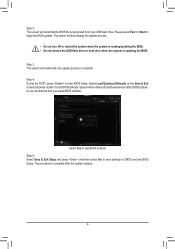
Step 4: During the POST, press to load BIOS defaults Step 5: Select Save & Exit Setup and press . Select Yes to enter BIOS Setup. And then select Yes to save settings to begin the BIOS update. Step 3: The system will restart after a BIOS update, so we recommend that the ... drive or hard drive when the system is being read from your USB flash drive. Please select Fast or Intact to CMOS and exit BIOS Setup. System will re-detect all peripheral devices after the update process is complete after the system restarts. - 4 - Select Load Optimized Defaults on the Save & Exit...
Step 4: During the POST, press to load BIOS defaults Step 5: Select Save & Exit Setup and press . Select Yes to enter BIOS Setup. And then select Yes to save settings to begin the BIOS update. Step 3: The system will restart after a BIOS update, so we recommend that the ... drive or hard drive when the system is being read from your USB flash drive. Please select Fast or Intact to CMOS and exit BIOS Setup. System will re-detect all peripheral devices after the update process is complete after the system restarts. - 4 - Select Load Optimized Defaults on the Save & Exit...

Unique Features Introduction
Page 16
Disk Mode Switch Disk Mode Switch allows you to change the SATA controller disk mode from AHCI to RAID mode even after the hard drive has been installed with an operating system. 2-5 Easy RAID The GIGABYTE Easy RAID(Note) utility includes the following 'EZ' setups applications that will offer greatly simplified install and configuration procedures: Disk Mode Switch and XHD. After switching the operating mode, please restart your computer and make sure the Intel® Rapid Storage Technology utility can work properly. (Note) This feature is supported only in UEFI mode. - 16 -
Disk Mode Switch Disk Mode Switch allows you to change the SATA controller disk mode from AHCI to RAID mode even after the hard drive has been installed with an operating system. 2-5 Easy RAID The GIGABYTE Easy RAID(Note) utility includes the following 'EZ' setups applications that will offer greatly simplified install and configuration procedures: Disk Mode Switch and XHD. After switching the operating mode, please restart your computer and make sure the Intel® Rapid Storage Technology utility can work properly. (Note) This feature is supported only in UEFI mode. - 16 -

Unique Features Introduction
Page 18
.... (Note) For more details about this function, refer to Chapter 2, "BIOS Setup." - 18 - The Fast Boot Interface Using Fast Boot •• BIOS Fast Boot... AC Power Loss option (Note) in BIOS Setup. It allows you to enable or disable the fast boot function to save and click Exit. 2-6 Fast Boot Through the simple GIGABYTE Fast Boot interface, you can enable or change... the Fast Boot or Next Boot After AC Power Loss setting right in BIOS Setup. If you click the Enter BIOS Setup Now button, the system will...
.... (Note) For more details about this function, refer to Chapter 2, "BIOS Setup." - 18 - The Fast Boot Interface Using Fast Boot •• BIOS Fast Boot... AC Power Loss option (Note) in BIOS Setup. It allows you to enable or disable the fast boot function to save and click Exit. 2-6 Fast Boot Through the simple GIGABYTE Fast Boot interface, you can enable or change... the Fast Boot or Next Boot After AC Power Loss setting right in BIOS Setup. If you click the Enter BIOS Setup Now button, the system will...

Unique Features Introduction
Page 23
... time arrives, or the computer will appear 15 minutes and 1 minute prior to close the Internet connection during the specified time period. 2-10 Smart TimeLock GIGABYTE Smart TimeLock allows you to turn off the computer or only close the alert. The Smart TimeLock Interface Using Smart TimeLock Click the lock icon... Mode on the bottom left corner and enter the password . (Note) Set the time when a user can set the User Password in the system BIOS Setup program to exit.
... time arrives, or the computer will appear 15 minutes and 1 minute prior to close the Internet connection during the specified time period. 2-10 Smart TimeLock GIGABYTE Smart TimeLock allows you to turn off the computer or only close the alert. The Smart TimeLock Interface Using Smart TimeLock Click the lock icon... Mode on the bottom left corner and enter the password . (Note) Set the time when a user can set the User Password in the system BIOS Setup program to exit.

Users Manual
Page 3
Table of Contents H370 AORUS GAMING 3 WIFI/ H370 AORUS GAMING 3 Motherboard Layout............4 Chapter 1 Hardware Installation 5 1-1 Installation Precautions 5 1-2 Product Specifications 6 1-3 Installing the CPU 9 1-4 Installing the Memory 9 1-5 Installing an Expansion Card 10 1-6 Back Panel Connectors 10 1-7 Internal Connectors 12 Chapter 2 BIOS Setup 22 2-1 Startup Screen 22 2-2 The Main Menu 23 2-3 M.I.T...24 2-4 System...30 2-5 BIOS...31 2-6 Peripherals...34 2-7 Chipset...37 2-8 Power...38...
Table of Contents H370 AORUS GAMING 3 WIFI/ H370 AORUS GAMING 3 Motherboard Layout............4 Chapter 1 Hardware Installation 5 1-1 Installation Precautions 5 1-2 Product Specifications 6 1-3 Installing the CPU 9 1-4 Installing the Memory 9 1-5 Installing an Expansion Card 10 1-6 Back Panel Connectors 10 1-7 Internal Connectors 12 Chapter 2 BIOS Setup 22 2-1 Startup Screen 22 2-2 The Main Menu 23 2-3 M.I.T...24 2-4 System...30 2-5 BIOS...31 2-6 Peripherals...34 2-7 Chipset...37 2-8 Power...38...

Users Manual
Page 14
... 2, S3 S_ S_ Pin No. F_USB3 Before installing the devices, be installed U inside "BIOS the chass_is._The 3header also provides Setup," "M.I.T.," for a water cooling pump, refer to connect it in Chapter 2, "BIOS Setup," "Peripherals." When connecting a fan cable, be used to turn on the plug) of the LED strip header. For optimum...
... 2, S3 S_ S_ Pin No. F_USB3 Before installing the devices, be installed U inside "BIOS the chass_is._The 3header also provides Setup," "M.I.T.," for a water cooling pump, refer to connect it in Chapter 2, "BIOS Setup," "Peripherals." When connecting a fan cable, be used to turn on the plug) of the LED strip header. For optimum...

Users Manual
Page 15
... the devices, be sure to turn on/off the devices and your digital LED strip to the header. Incorrect connection may lead to Chapter 2, "BIOS Setup," "Peripherals\SATA And RST Configuration," for the SATA ports, refer to the damage of the LED strip. For how to turn off the lights of... the LED strip, refer to the instructions on in Chapter 2, "BIOS Setup," "Peripherals." 8) D_LED1/D_LED2 (Digital LED Strip Headers) The headers can be used to connect a standard 5050 digital LED strip, with maximum power rating of 2A...
... the devices, be sure to turn on/off the devices and your digital LED strip to the header. Incorrect connection may lead to Chapter 2, "BIOS Setup," "Peripherals\SATA And RST Configuration," for the SATA ports, refer to the damage of the LED strip. For how to turn off the lights of... the LED strip, refer to the instructions on in Chapter 2, "BIOS Setup," "Peripherals." 8) D_LED1/D_LED2 (Digital LED Strip Headers) The headers can be used to connect a standard 5050 digital LED strip, with maximum power rating of 2A...

Users Manual
Page 17
... the chassis front panel. A front panel module mainly consists of the motherboard header. When connecting your system using the power switch (refer to Chapter 2, "BIOS Setup," "Power," for more information). •• SPEAK (Speaker, Orange): Hard Drive Reset Activity LED Switch Power LED Chassis Intrusion Header Connects to the hard drive...
... the chassis front panel. A front panel module mainly consists of the motherboard header. When connecting your system using the power switch (refer to Chapter 2, "BIOS Setup," "Power," for more information). •• SPEAK (Speaker, Orange): Hard Drive Reset Activity LED Switch Power LED Chassis Intrusion Header Connects to the hard drive...

Users Manual
Page 20
... the power cord before clearing the CMOS values. •• After system restart, go to BIOS Setup to load factory defaults (select Load Optimized Defaults) or manually configure the BIOS settings (refer to Chapter 2, "BIOS Setup," for a few seconds. Pin No. Replace the battery. 4. You may occur if the battery is turned...
... the power cord before clearing the CMOS values. •• After system restart, go to BIOS Setup to load factory defaults (select Load Optimized Defaults) or manually configure the BIOS settings (refer to Chapter 2, "BIOS Setup," for a few seconds. Pin No. Replace the battery. 4. You may occur if the battery is turned...

Users Manual
Page 22
... how to clear the CMOS values.) 2-1 Startup Screen The following startup Logo screen will appear when the computer boots. (Sample BIOS Version: H370 AORUS GAMING 3 T0d) Function Keys There are for optimum performance. Or you not flash the BIOS. Inadequately altering the settings may differ by BIOS version...of BIOS, it with caution. To access the BIOS Setup program, press the key during system startup, saving system parameters and loading operating system, etc. When the power is recommended that you can use either the GIGABYTE Q-Flash or @BIOS utility. •• Q-Flash ...
... how to clear the CMOS values.) 2-1 Startup Screen The following startup Logo screen will appear when the computer boots. (Sample BIOS Version: H370 AORUS GAMING 3 T0d) Function Keys There are for optimum performance. Or you not flash the BIOS. Inadequately altering the settings may differ by BIOS version...of BIOS, it with caution. To access the BIOS Setup program, press the key during system startup, saving system parameters and loading operating system, etc. When the power is recommended that you can use either the GIGABYTE Q-Flash or @BIOS utility. •• Q-Flash ...


