
User Manual
Page 12
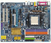
...), allows connection of 4 IDE devices Š 1 FDD connection, allows connection of 2 FDD devices Š 4 SATA 3Gb/s ports from nVIDIA® nForce4 SLI controller (S_ATA0_SB, S_ATA1_SB, S_ATA2_SB, S_ATA3_SB); Š 4 SATA ports from SiI3114 controller (SATA0_SII, SATA1_SII, SATA2_SII, SATA3_SII) Š 1 parallel port supporting ... Audio Š GA-K8N Ultra-SLI or GA-K8N Pro-SLI or GA-K8N-SLI Š Socket 939 for AMD AthlonTM 64 / 64 FX processor (K8) Š 2000MT/s system bus Š Supports core frequencies in excess of 3000+ and faster Š nVIDIA® nForce4 SLI Chipset Š 4 ...
...), allows connection of 4 IDE devices Š 1 FDD connection, allows connection of 2 FDD devices Š 4 SATA 3Gb/s ports from nVIDIA® nForce4 SLI controller (S_ATA0_SB, S_ATA1_SB, S_ATA2_SB, S_ATA3_SB); Š 4 SATA ports from SiI3114 controller (SATA0_SII, SATA1_SII, SATA2_SII, SATA3_SII) Š 1 parallel port supporting ... Audio Š GA-K8N Ultra-SLI or GA-K8N Pro-SLI or GA-K8N-SLI Š Socket 939 for AMD AthlonTM 64 / 64 FX processor (K8) Š 2000MT/s system bus Š Supports core frequencies in excess of 3000+ and faster Š nVIDIA® nForce4 SLI Chipset Š 4 ...

User Manual
Page 13
... rate of 4 SATA 3Gb/s connections Onboard Silicon Image SiI3114 chip (SATA0_SII, SATA1_SII, SATA2_SII, SATA3_SII) - Only for GA-K8N Ultra-SLI. supports a maximum of licensed AWARD BIOS Supports Dual BIOS /Q-Flash Supports @BIOS Supports EasyTune 5 (Note 2) Over Voltage via...CPU smart fan control Onboard nForce4 SLI chipset (S_ATA0_SB, S_ATA1_SB, S_ATA2_SB, S_ATA3_SB) - supports a maximum of up to 300 MB/s - supports hot plugging function - supports data striping (RAID 0), mirroring (RAID 1), striping + mirroring (RAID 0+1) or RAID 5 - Only for GA-K8N Pro-SLI. - 13 - supports ...
... rate of 4 SATA 3Gb/s connections Onboard Silicon Image SiI3114 chip (SATA0_SII, SATA1_SII, SATA2_SII, SATA3_SII) - Only for GA-K8N Ultra-SLI. supports a maximum of licensed AWARD BIOS Supports Dual BIOS /Q-Flash Supports @BIOS Supports EasyTune 5 (Note 2) Over Voltage via...CPU smart fan control Onboard nForce4 SLI chipset (S_ATA0_SB, S_ATA1_SB, S_ATA2_SB, S_ATA3_SB) - supports a maximum of up to 300 MB/s - supports hot plugging function - supports data striping (RAID 0), mirroring (RAID 1), striping + mirroring (RAID 0+1) or RAID 5 - Only for GA-K8N Pro-SLI. - 13 - supports ...

User Manual
Page 14
... installing the CPU. If you install the CPU in Figure 2. The CPU will not insert properly. Please add an even layer of the CPU. K8 nForce4 SLI Series Motherboard - 14 - If you wish to the unlocked position as shown in the wrong direction, the CPU will not fit if positioned incorrectly. Move...
... installing the CPU. If you install the CPU in Figure 2. The CPU will not insert properly. Please add an even layer of the CPU. K8 nForce4 SLI Series Motherboard - 14 - If you wish to the unlocked position as shown in the wrong direction, the CPU will not fit if positioned incorrectly. Move...

User Manual
Page 16
... design. The motherboard supports DDR memory modules, whereby BIOS will automatically detect memory capacity and specifications. The memory capacity used . 2. Then push it down. K8 nForce4 SLI Series Motherboard - 16 - Please make sure that the computer power is switched off to prevent hardware damage. 3. Memory modules are unable to insert the module...
... design. The motherboard supports DDR memory modules, whereby BIOS will automatically detect memory capacity and specifications. The memory capacity used . 2. Then push it down. K8 nForce4 SLI Series Motherboard - 16 - Please make sure that the computer power is switched off to prevent hardware damage. 3. Memory modules are unable to insert the module...

User Manual
Page 18
... card to install/uninstall the VGA card. English 1-5 Installation of Expansion Cards You can install your expansion card by the small white-drawable bar. K8 nForce4 SLI Series Motherboard - 18 - Make sure your VGA card is locked by following the steps outlined below: 1. Replace the screw to secure the slot bracket of...
... card to install/uninstall the VGA card. English 1-5 Installation of Expansion Cards You can install your expansion card by the small white-drawable bar. K8 nForce4 SLI Series Motherboard - 18 - Make sure your VGA card is locked by following the steps outlined below: 1. Replace the screw to secure the slot bracket of...
User Manual
Page 19
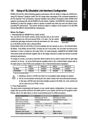
... x 8 slots or install two SLI-ready PCIE x 16 cards (Example: GIGABYTE GV-NX66T128D) of the same model and link them together with the gold edge connector on the GA-K8N Ulra-SLI/GA-K8N Pro-SLI/GA-K8N-SLI motherboard. English 1-6 Setup of SLI (Scalable Link Interface) Configuration NVIDIA nForce4 SLI offers blistering graphics performance with an SLI switch SLI Mode module between the...
... x 8 slots or install two SLI-ready PCIE x 16 cards (Example: GIGABYTE GV-NX66T128D) of the same model and link them together with the gold edge connector on the GA-K8N Ulra-SLI/GA-K8N Pro-SLI/GA-K8N-SLI motherboard. English 1-6 Setup of SLI (Scalable Link Interface) Configuration NVIDIA nForce4 SLI offers blistering graphics performance with an SLI switch SLI Mode module between the...

User Manual
Page 20
... on your system is to the PCIE_16_1 and PCIE_16_2 slots. Step 4: Gently press down on page 16 and install two SLI-ready graphics cards of the module until it is locked in place by the socket clips. (You should hear a "click" when the module is currrently ... and insert it away from the socket. Step 1: Gently spread the retaining clips of the module into the socket. K8 nForce4 SLI Series Motherboard - 20 - Enabling SLI Mode-Follow the steps below to enable SLI Mode. Align the small notch at the top edge of the module above the socket at a 25o angle. Make...
... on your system is to the PCIE_16_1 and PCIE_16_2 slots. Step 4: Gently press down on page 16 and install two SLI-ready graphics cards of the module until it is locked in place by the socket clips. (You should hear a "click" when the module is currrently ... and insert it away from the socket. Step 1: Gently spread the retaining clips of the module into the socket. K8 nForce4 SLI Series Motherboard - 20 - Enabling SLI Mode-Follow the steps below to enable SLI Mode. Align the small notch at the top edge of the module above the socket at a 25o angle. Make...
User Manual
Page 22
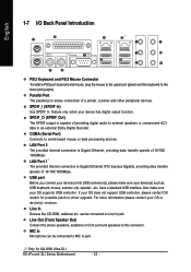
...providing digital audio to external speakers or compressed AC3 data to Line In jack. can be connected to an external Dolby Digital Decoder. K8 nForce4 SLI Series Motherboard - 22 - Parallel Port The parallel port allows connection of 10/100/ 1000Mbps. SPDIF_I (SPDIF In) Use SPDIF In ...only when your OS supports USB controller. Also make sure your OS does not support USB controller, please contact OS vendor for GA-K8N Ultra-SLI. COMA (Serial Port) Connects to this connector. USB port Before you connect your device(s) into USB connector(s), please make sure ...
...providing digital audio to external speakers or compressed AC3 data to Line In jack. can be connected to an external Dolby Digital Decoder. K8 nForce4 SLI Series Motherboard - 22 - Parallel Port The parallel port allows connection of 10/100/ 1000Mbps. SPDIF_I (SPDIF In) Use SPDIF In ...only when your OS supports USB controller. Also make sure your OS does not support USB controller, please contact OS vendor for GA-K8N Ultra-SLI. COMA (Serial Port) Connects to this connector. USB port Before you connect your device(s) into USB connector(s), please make sure ...

User Manual
Page 24
... +5V 1 13 11 +12V(Onlyfor24-pinATX) 23 +5V (Only for 24-pin ATX) 12 3.3V(Onlyfor24-pinATX) 24 GND(Only for 24-pin ATX) K8 nForce4 SLI Series Motherboard - 24 - The ATX_12V power connector mainly supplies power to all components and devices are properly installed. If a power supply is not connected, the...
... +5V 1 13 11 +12V(Onlyfor24-pinATX) 23 +5V (Only for 24-pin ATX) 12 3.3V(Onlyfor24-pinATX) 24 GND(Only for 24-pin ATX) K8 nForce4 SLI Series Motherboard - 24 - The ATX_12V power connector mainly supplies power to all components and devices are properly installed. If a power supply is not connected, the...

User Manual
Page 26
... to the pin1 position. 34 33 2 1 8) IDE1 / IDE2 (IDE Connector) An IDE device connects to the instructions located on the IDE device). 40 39 2 1 K8 nForce4 SLI Series Motherboard - 26 - The types of the cable connects to two IDE devices (hard drive or optical drive). If you wish to connect two IDE...
... to the pin1 position. 34 33 2 1 8) IDE1 / IDE2 (IDE Connector) An IDE device connects to the instructions located on the IDE device). 40 39 2 1 K8 nForce4 SLI Series Motherboard - 26 - The types of the cable connects to two IDE devices (hard drive or optical drive). If you wish to connect two IDE...

User Manual
Page 27
...Audio (L)/ Return L Only for the Serial ATA controller(s)and install the proper driver in order to work properly. 7 1 S_ATA_SB (Controlled by nForce4 SLI) 7 1 Pin No. 1 2 3 4 5 6 7 Definition GND TXP TXN GND RXN RXP GND SATA_SII (Controlled by Sil3114) SATA..., please contact your chassis must remove 5-6, 9-10 Jumper. English 9) S_ATA0/1/2/3_SB (SATA 3Gb/s Connectors, Controlled by nForce4 SLI) 10) SATA0/1/2/3_SII (SATA Connectors, Controlled by Sil3114) 11) F_AUDIO (Front Audio Panel Connector) If you want ... rate. Please refer to the BIOS setting for GA-K8N Ultra-SLI. - 27 -
...Audio (L)/ Return L Only for the Serial ATA controller(s)and install the proper driver in order to work properly. 7 1 S_ATA_SB (Controlled by nForce4 SLI) 7 1 Pin No. 1 2 3 4 5 6 7 Definition GND TXP TXN GND RXN RXP GND SATA_SII (Controlled by Sil3114) SATA..., please contact your chassis must remove 5-6, 9-10 Jumper. English 9) S_ATA0/1/2/3_SB (SATA 3Gb/s Connectors, Controlled by nForce4 SLI) 10) SATA0/1/2/3_SII (SATA Connectors, Controlled by Sil3114) 11) F_AUDIO (Front Audio Panel Connector) If you want ... rate. Please refer to the BIOS setting for GA-K8N Ultra-SLI. - 27 -

User Manual
Page 28
... below. Pin 3: NC Pin 4: Data(-) Open: Normal Close: Reset Hardware System Open: Normal Close: Power On/Off Pin 1: LED anode(+) Pin 2: LED cathode(-) NC K8 nForce4 SLI Series Motherboard - 28 - Speaker Connector Power Switch Message LED/ Power/ Sleep LED SPEAK- 20 19 SPEAK+ PWPW+ MSGMSG+ 21 NCRES+ RES- HDHD+ Reset Switch IDE...
... below. Pin 3: NC Pin 4: Data(-) Open: Normal Close: Reset Hardware System Open: Normal Close: Power On/Off Pin 1: LED anode(+) Pin 2: LED cathode(-) NC K8 nForce4 SLI Series Motherboard - 28 - Speaker Connector Power Switch Message LED/ Power/ Sleep LED SPEAK- 20 19 SPEAK+ PWPW+ MSGMSG+ 21 NCRES+ RES- HDHD+ Reset Switch IDE...

User Manual
Page 30
... cable, please contact your local dealer. 2 10 1 9 Pin No. 1 2 3 4 5 6 7 8 9 10 Definition Power Power USB DXUSB DyUSB DX+ USB Dy+ GND GND No Pin NC K8 nForce4 SLI Series Motherboard - 30 - Check the pin assignment carefully while you connect the IR/CIR cable, incorrect connection between the cable and connector will make the...
... cable, please contact your local dealer. 2 10 1 9 Pin No. 1 2 3 4 5 6 7 8 9 10 Definition Power Power USB DXUSB DyUSB DX+ USB Dy+ GND GND No Pin NC K8 nForce4 SLI Series Motherboard - 30 - Check the pin assignment carefully while you connect the IR/CIR cable, incorrect connection between the cable and connector will make the...

User Manual
Page 32
... the power cord. 2. Plug the power cord and turn ON the computer. Replace only with the same or equivalent type recommended by the manufacturer. K8 nForce4 SLI Series Motherboard - 32 - Re-install the battery. 4. Dispose of explosion if battery is incorrectly replaced.
... the power cord. 2. Plug the power cord and turn ON the computer. Replace only with the same or equivalent type recommended by the manufacturer. K8 nForce4 SLI Series Motherboard - 32 - Re-install the battery. 4. Dispose of explosion if battery is incorrectly replaced.

User Manual
Page 34
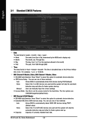
... frequency ratio. „ Top Performance If you enter Award BIOS CMOS Setup Utility, the Main Menu (as figure below) will appear on the screen. K8 nForce4 SLI Series Motherboard - 34 - If you can't find the setting you want, please press "Ctrl+F1" to search the advanced option hidden. „ Standard CMOS Features... in best performance configuration. The Main Menu (For example: BIOS Ver. : F6a) Once you wish to accept or enter the sub-menu. Only for GA-K8N Pro-SLI. Only for GA-K8N Ultra-SLI.
... frequency ratio. „ Top Performance If you enter Award BIOS CMOS Setup Utility, the Main Menu (as figure below) will appear on the screen. K8 nForce4 SLI Series Motherboard - 34 - If you can't find the setting you want, please press "Ctrl+F1" to search the advanced option hidden. „ Standard CMOS Features... in best performance configuration. The Main Menu (For example: BIOS Ver. : F6a) Once you wish to accept or enter the sub-menu. Only for GA-K8N Pro-SLI. Only for GA-K8N Ultra-SLI.
User Manual
Page 36
...:00. For example, 1 p.m. The four options are: CHS/LBA/Large/Auto(default:Auto) IDE Channel 2/3/4/5 Master IDE HDD Auto-Detection Press "Enter" to Dec. K8 nForce4 SLI Series Motherboard - 36 - Through Dec. to select this option for automatic device detection. Jan. You can use one of two methods: Auto Allows BIOS to...
...:00. For example, 1 p.m. The four options are: CHS/LBA/Large/Auto(default:Auto) IDE Channel 2/3/4/5 Master IDE HDD Auto-Detection Press "Enter" to Dec. K8 nForce4 SLI Series Motherboard - 36 - Through Dec. to select this option for automatic device detection. Jan. You can use one of two methods: Auto Allows BIOS to...

User Manual
Page 38
... Disk. USB-HDD Select your boot device priority by Floppy. Use < > or < > to select a device, then press to move it is 360K. (Default value) K8 nForce4 SLI Series Motherboard - 38 - Disabled Disable this menu. Hard Disk Select your boot device priority by USB-CDROM. USB-ZIP Select your boot device priority by...
... Disk. USB-HDD Select your boot device priority by Floppy. Use < > or < > to select a device, then press to move it is 360K. (Default value) K8 nForce4 SLI Series Motherboard - 38 - Disabled Disable this menu. Hard Disk Select your boot device priority by USB-CDROM. USB-ZIP Select your boot device priority by...

User Manual
Page 40
IDE DMA transfer access Enabled Enable IDE DMA transfer access. (Default value) Disabled Disable this function. Only for GA-K8N Ultra-SLI. English 2-3 Integrated Peripherals CMOS Setup Utility-Copyright (C) 1984-2005 Award Software Integrated Peripherals On-Chip IDE Channel0 On-Chip IDE Channel1 IDE DMA transfer access ...-Chip IDE Channel1 Enabled Enable onboard 2nd channel IDE port. (Default value) Disabled Disable onboard 2nd channel IDE port. F1: General Help Only for GA-K8N Pro-SLI. K8 nForce4 SLI Series Motherboard - 40 -
IDE DMA transfer access Enabled Enable IDE DMA transfer access. (Default value) Disabled Disable this function. Only for GA-K8N Ultra-SLI. English 2-3 Integrated Peripherals CMOS Setup Utility-Copyright (C) 1984-2005 Award Software Integrated Peripherals On-Chip IDE Channel0 On-Chip IDE Channel1 IDE DMA transfer access ...-Chip IDE Channel1 Enabled Enable onboard 2nd channel IDE port. (Default value) Disabled Disable onboard 2nd channel IDE port. F1: General Help Only for GA-K8N Pro-SLI. K8 nForce4 SLI Series Motherboard - 40 -

User Manual
Page 42
...drive is connected to the SATA0 or SATA1 connector , please set "NV SATA1 class code" to create RAID data drive or install O.S. K8 nForce4 SLI Series Motherboard - 42 - NV SATA 2 Primary RAID Enabled Enable 2nd SATA primary RAID function. (Default value) Disabled Disable this function. Onboard... connected to the SATA2 or SATA3 connector , please set "NV SATA1/NV SATA 2 class code" from 0101 to 0104. Only for GA-K8N Pro-SLI. IDE Prefetch Mode Enabled Disabled Enable IDE Prefetch mode. (Default value) Disable IDE Prefetch mode. English NV SATA 2 class code(Note) 0101...
...drive is connected to the SATA0 or SATA1 connector , please set "NV SATA1 class code" to create RAID data drive or install O.S. K8 nForce4 SLI Series Motherboard - 42 - NV SATA 2 Primary RAID Enabled Enable 2nd SATA primary RAID function. (Default value) Disabled Disable this function. Onboard... connected to the SATA2 or SATA3 connector , please set "NV SATA1/NV SATA 2 class code" from 0101 to 0104. Only for GA-K8N Pro-SLI. IDE Prefetch Mode Enabled Disabled Enable IDE Prefetch mode. (Default value) Disable IDE Prefetch mode. English NV SATA 2 class code(Note) 0101...
User Manual
Page 44
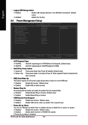
... Ring on the 5VSB lead. USB Resume from suspend type. If Power-On by Power button Instant-off Press power button then Power off . K8 nForce4 SLI Series Motherboard - 44 - Soft-Off by Alarm is pressed less than 4 seconds. PME Event Wake Up This feature requires an ATX power supply that provides...
... Ring on the 5VSB lead. USB Resume from suspend type. If Power-On by Power button Instant-off Press power button then Power off . K8 nForce4 SLI Series Motherboard - 44 - Soft-Off by Alarm is pressed less than 4 seconds. PME Event Wake Up This feature requires an ATX power supply that provides...


