Manual
Page 1
MN525RI MN525MI Intel® D525 Processor Motherboards User's Manual Rev. 1001
MN525RI MN525MI Intel® D525 Processor Motherboards User's Manual Rev. 1001
Manual
Page 3
Table of Contents MN525RI Motherboard Layout 4 Chapter 1 Hardware Installation 6 1-1 Installation Precautions 6 1-2 Product Specifications 7 1-3 Installing the Memory 9 1-3-1 Dual Channel Memory Configuration 9 1-3-2 Installing a Memory 10 1-4 Back Panel Connectors 11 1-5 Internal Connectors 12 - 3 -
Table of Contents MN525RI Motherboard Layout 4 Chapter 1 Hardware Installation 6 1-1 Installation Precautions 6 1-2 Product Specifications 7 1-3 Installing the Memory 9 1-3-1 Dual Channel Memory Configuration 9 1-3-2 Installing a Memory 10 1-4 Back Panel Connectors 11 1-5 Internal Connectors 12 - 3 -
Manual
Page 4
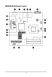
MN525RI Motherboard Layout - 4 -
MN525RI Motherboard Layout - 4 -
Manual
Page 6
... and power connectors of your dealer. ponents such as a result of electrostatic discharge (ESD). Chapter 1 Hardware Installation 1-1 Installation Precautions The motherboard contains numerous delicate electronic circuits and components which can lead to damage to system components as well as physical harm to the user. •... ESD wrist strap, keep your hands dry and first touch a metal object to eliminate static electricity. • Prior to installing the motherboard, please have it on top of an antistatic pad or within the computer casing. • Do not place the computer system on...
... and power connectors of your dealer. ponents such as a result of electrostatic discharge (ESD). Chapter 1 Hardware Installation 1-1 Installation Precautions The motherboard contains numerous delicate electronic circuits and components which can lead to damage to system components as well as physical harm to the user. •... ESD wrist strap, keep your hands dry and first touch a metal object to eliminate static electricity. • Prior to installing the motherboard, please have it on top of an antistatic pad or within the computer casing. • Do not place the computer system on...
Manual
Page 9
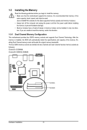
...the same capacity, brand, speed, and chips be installed in only one direction. A memory module can be used. (Go to GIGABYTE's website for the latest supported memory speeds and memory modules.) • Always turn off the computer and unplug the power cord from... two memory sockets as following guidelines before installing the memory to insert the memory, switch the direction. 1-3-1 Dual Channel Memory Configuration This motherboard provides four DDR3 memory sockets and supports Dual Channel Technology. 1-3 Installing the Memory Read the following : Channel A: SODIMMA Channel B: DIMM1B...
...the same capacity, brand, speed, and chips be installed in only one direction. A memory module can be used. (Go to GIGABYTE's website for the latest supported memory speeds and memory modules.) • Always turn off the computer and unplug the power cord from... two memory sockets as following guidelines before installing the memory to insert the memory, switch the direction. 1-3-1 Dual Channel Memory Configuration This motherboard provides four DDR3 memory sockets and supports Dual Channel Technology. 1-3 Installing the Memory Read the following : Channel A: SODIMMA Channel B: DIMM1B...
Manual
Page 10
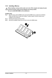
Installation Step: Step 1. Reverse the installation steps when you wish to install DDR3 DIMMs on this motherboard. Align the memory with the DIMM module and insert the DIMM memory module into the DIM slot. A memory module can be installed In only one ...
Installation Step: Step 1. Reverse the installation steps when you wish to install DDR3 DIMMs on this motherboard. Align the memory with the DIMM module and insert the DIMM memory module into the DIM slot. A memory module can be installed In only one ...
Manual
Page 11
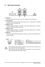
... describes the states of the LAN port LEDs. USB 2.0/1.1 Port The USB port supports the USB 2.0/1.1 specification. Do not rock it straight out from the motherboard. • When removing the cable, pull it side to side to a back panel connector, first remove the cable from your device and then remove it...
... describes the states of the LAN port LEDs. USB 2.0/1.1 Port The USB port supports the USB 2.0/1.1 specification. Do not rock it straight out from the motherboard. • When removing the cable, pull it side to side to a back panel connector, first remove the cable from your device and then remove it...

Manual
Page 12
... devices and your devices are compliant with the connectors you wish to connect. • Before installing the devices, be sure to the connector on the motherboard. Hardware Installation - 12 -
... devices and your devices are compliant with the connectors you wish to connect. • Before installing the devices, be sure to the connector on the motherboard. Hardware Installation - 12 -
Manual
Page 13
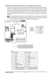
...-pin ATX) GND (Only for 2x12-pin ATX) Hardware Installation - 13 - If the 12V power connector is turned off and all the components on the motherboard. ATX_12V FDD Pin No. To meet expansion requirements, it is used that can withstand high power consumption be used (500W or greater). The power connector...
...-pin ATX) GND (Only for 2x12-pin ATX) Hardware Installation - 13 - If the 12V power connector is turned off and all the components on the motherboard. ATX_12V FDD Pin No. To meet expansion requirements, it is used that can withstand high power consumption be used (500W or greater). The power connector...
Manual
Page 14
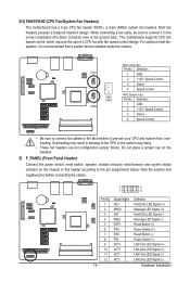
...chassis intrusion switch/sensor and system status indicator on the chassis to this header according to prevent your CPU and system from overheating. PW- The motherboard supports CPU fan speed control, which requires the use of a CPU fan with fan speed control design. Signal Name HD+ MSG+ HD-...Control • Be sure to connect fan cables to the fan headers to the pin assignments below. 2/3) FAN1/FAN2 (CPU Fan/System Fan Headers) The motherboard has a 4-pin CPU fan header (FAN1), a 4-pin (FAN2) system fan headers. MSG- ACT+ ACT+ ACT- For optimum heat dissipation, it ...
...chassis intrusion switch/sensor and system status indicator on the chassis to this header according to prevent your CPU and system from overheating. PW- The motherboard supports CPU fan speed control, which requires the use of a CPU fan with fan speed control design. Signal Name HD+ MSG+ HD-...Control • Be sure to connect fan cables to the fan headers to the pin assignments below. 2/3) FAN1/FAN2 (CPU Fan/System Fan Headers) The motherboard has a 4-pin CPU fan header (FAN1), a 4-pin (FAN2) system fan headers. MSG- ACT+ ACT+ ACT- For optimum heat dissipation, it ...
Manual
Page 18
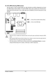
..., place a jumper cap on your computer, be sure to touch the two pins for BIOS configurations). Failure to do so may cause damage to the motherboard. • After system restart, go to BIOS Setup to load factory defaults (select Load Optimized Defaults) or manually configure the BIOS settings (refer to Chapter...
..., place a jumper cap on your computer, be sure to touch the two pins for BIOS configurations). Failure to do so may cause damage to the motherboard. • After system restart, go to BIOS Setup to load factory defaults (select Load Optimized Defaults) or manually configure the BIOS settings (refer to Chapter...


