
User Manual
Page 2
...product-related information, check on our website at: https://www.gigabyte.com Identifying Your Motherboard Revision The revision number on your motherboard revision before updating motherboard BIOS, drivers, or when looking for technical information. Check your motherboard looks like this manual may be reproduced, copied, translated, ...„„ For quick set-up of GIGABYTE. Example: All rights reserved. Disclaimer Information in this manual is protected by any form or by copyright laws and is 1.0. No part of the motherboard is the property of the product, read ...
...product-related information, check on our website at: https://www.gigabyte.com Identifying Your Motherboard Revision The revision number on your motherboard revision before updating motherboard BIOS, drivers, or when looking for technical information. Check your motherboard looks like this manual may be reproduced, copied, translated, ...„„ For quick set-up of GIGABYTE. Example: All rights reserved. Disclaimer Information in this manual is protected by any form or by copyright laws and is 1.0. No part of the motherboard is the property of the product, read ...
User Manual
Page 3
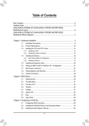
Table of Contents Box Contents...5 Optional Items...5 Z490 AORUS XTREME WF (Z490 AORUS XTREME WATERFORCE) Motherboard Layout...6 Z490 AORUS XTREME WF (Z490 AORUS XTREME WATERFORCE) Motherboard Block Diagram 7 Chapter 1 Hardware Installation 9 1-1 Installation Precautions 9 1-2 Product Specifications 10 1-3 Installing the CPU and CPU Cooler 14 1-3-1 Installing the CPU...14 1-3-2 Installing the Water Cooling ...
Table of Contents Box Contents...5 Optional Items...5 Z490 AORUS XTREME WF (Z490 AORUS XTREME WATERFORCE) Motherboard Layout...6 Z490 AORUS XTREME WF (Z490 AORUS XTREME WATERFORCE) Motherboard Block Diagram 7 Chapter 1 Hardware Installation 9 1-1 Installation Precautions 9 1-2 Product Specifications 10 1-3 Installing the CPU and CPU Cooler 14 1-3-1 Installing the CPU...14 1-3-2 Installing the Water Cooling ...
User Manual
Page 5
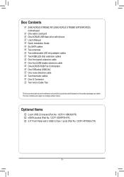
The box contents are for reference only and the actual items shall depend on the product package you obtain. Box Contents 55 Z490 AORUS XTREME WF (Z490 AORUS XTREME WATERFORCE) motherboard 55 One water cooling kit 55 One AORUS USB flash drive with 2 USB 3.2 Gen 1 ports (Part No. 12CR1-FPX582-2*R) - 5 - Optional Items †† 2-port USB...cables 55 Two RGB LED strip extension cables 55 One front panel extension cable 55 One front USB header extension cable 55 One AORUS RGB Fan Commander 55 One ESSential USB DAC 55 One noise detection cable 55 Two thermistor cables 55 One G Connector 55 ...
The box contents are for reference only and the actual items shall depend on the product package you obtain. Box Contents 55 Z490 AORUS XTREME WF (Z490 AORUS XTREME WATERFORCE) motherboard 55 One water cooling kit 55 One AORUS USB flash drive with 2 USB 3.2 Gen 1 ports (Part No. 12CR1-FPX582-2*R) - 5 - Optional Items †† 2-port USB...cables 55 Two RGB LED strip extension cables 55 One front panel extension cable 55 One front USB header extension cable 55 One AORUS RGB Fan Commander 55 One ESSential USB DAC 55 One noise detection cable 55 Two thermistor cables 55 One G Connector 55 ...
User Manual
Page 6
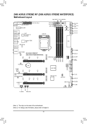
Z490 AORUS XTREME WF (Z490 AORUS XTREME WATERFORCE) Motherboard Layout DB_PORT (Note 2) OC_IGNITION EC_TEMP1 EC_TEMP2 SYS_FAN1 REAR_BUTTON ATX_12V_2X4_1 CNVI_WIFI ATX_12V_2X4_2 CPU_FAN CPU_OPT LED_CPU TYPEC_1 U32G2_LAN2 TYPEC_2 U32G2_LAN1 Intel® Thunderbolt™ 3 Controller USB_HDMI Aquantia 10GbE LAN USB 2.0 Hub U32_G2 LGA1200 PW_SW RST_SW SYS_FAN6_ PUMP SYS_FAN5_ PUMP SYS_FAN4 SYS_FAN3 SYS_FAN2 ATX AUDIO Intel® 2.5GbE LAN Z490 AORUS XTREME WF (Z490 AORUS XTREME WATERFORCE) 110 80 42...
Z490 AORUS XTREME WF (Z490 AORUS XTREME WATERFORCE) Motherboard Layout DB_PORT (Note 2) OC_IGNITION EC_TEMP1 EC_TEMP2 SYS_FAN1 REAR_BUTTON ATX_12V_2X4_1 CNVI_WIFI ATX_12V_2X4_2 CPU_FAN CPU_OPT LED_CPU TYPEC_1 U32G2_LAN2 TYPEC_2 U32G2_LAN1 Intel® Thunderbolt™ 3 Controller USB_HDMI Aquantia 10GbE LAN USB 2.0 Hub U32_G2 LGA1200 PW_SW RST_SW SYS_FAN6_ PUMP SYS_FAN5_ PUMP SYS_FAN4 SYS_FAN3 SYS_FAN2 ATX AUDIO Intel® 2.5GbE LAN Z490 AORUS XTREME WF (Z490 AORUS XTREME WATERFORCE) 110 80 42...
User Manual
Page 7
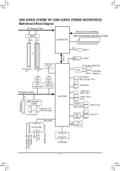
Z490 AORUS XTREME WF (Z490 AORUS XTREME WATERFORCE) Motherboard Block Diagram PCI Express 3.0 Bus Switch x16 x8 LGA1200 CPU CPU CLK+/- (100~500 MHz) DDR4 3200/3000/2933/2666/2400/2133 MHz or 1 PCI ... 2 USB Type-C™, with or USB 3.2 Gen 2 support 2 Intel® Thunderbolt™ 3 ALC1220-VB + ESS ES9018K2M + TI OPA1622 Rear Audio DDI HDMI 1.4 DMI 3.0 Intel® Z490 SPI Dual BIOS Bus 1 M.2 Socket 3 (M2M_PCH) Switch 2 SATA 6Gb/s (SATA3 4, 5) 2 M.2 Socket 3 (M2A_CPU, M2P_PCH ) 4 SATA 6Gb/s 1 USB Type-C™, USB 3.2 Gen 2 4 USB 3.2 Gen 2 Type A USB 3.2 Gen...
Z490 AORUS XTREME WF (Z490 AORUS XTREME WATERFORCE) Motherboard Block Diagram PCI Express 3.0 Bus Switch x16 x8 LGA1200 CPU CPU CLK+/- (100~500 MHz) DDR4 3200/3000/2933/2666/2400/2133 MHz or 1 PCI ... 2 USB Type-C™, with or USB 3.2 Gen 2 support 2 Intel® Thunderbolt™ 3 ALC1220-VB + ESS ES9018K2M + TI OPA1622 Rear Audio DDI HDMI 1.4 DMI 3.0 Intel® Z490 SPI Dual BIOS Bus 1 M.2 Socket 3 (M2M_PCH) Switch 2 SATA 6Gb/s (SATA3 4, 5) 2 M.2 Socket 3 (M2A_CPU, M2P_PCH ) 4 SATA 6Gb/s 1 USB Type-C™, USB 3.2 Gen 2 4 USB 3.2 Gen 2 Type A USB 3.2 Gen...
User Manual
Page 9
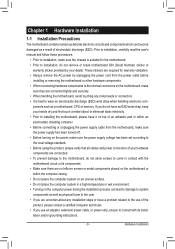
... please verify that all cables and power connectors of electrostatic discharge (ESD). Chapter 1 Hardware Installation 1-1 Installation Precautions The motherboard contains numerous delicate electronic circuits and components which can lead to damage to system components as well as physical harm to... computer technician. •• If you use an adapter, extension power cable, or power strip, ensure to consult with the motherboard circuit or its installation and/or grounding instructions. - 9 - Hardware Installation Prior to installation, carefully read the user's manual and...
... please verify that all cables and power connectors of electrostatic discharge (ESD). Chapter 1 Hardware Installation 1-1 Installation Precautions The motherboard contains numerous delicate electronic circuits and components which can lead to damage to system components as well as physical harm to... computer technician. •• If you use an adapter, extension power cable, or power strip, ensure to consult with the motherboard circuit or its installation and/or grounding instructions. - 9 - Hardware Installation Prior to installation, carefully read the user's manual and...
User Manual
Page 13
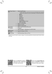
...XSplit Gamecaster + Broadcaster (12 months license) Support for Windows 10 64-bit E-ATX Form Factor; 30.5cm x 27.1cm * GIGABYTE reserves the right to make any changes to download the latest version of apps. Fast Boot - RGB Fusion - Hardware Installation Unique ... System Form Factor Š Support for support lists of each application may vary by motherboard model. Please visit the Support\Utility List page on motherboard specifications. - @BIOS - EasyTune - Please visit GIGABYTE's website for APP Center * Available applications in APP Center may also vary depending on...
...XSplit Gamecaster + Broadcaster (12 months license) Support for Windows 10 64-bit E-ATX Form Factor; 30.5cm x 27.1cm * GIGABYTE reserves the right to make any changes to download the latest version of apps. Fast Boot - RGB Fusion - Hardware Installation Unique ... System Form Factor Š Support for support lists of each application may vary by motherboard model. Please visit the Support\Utility List page on motherboard specifications. - @BIOS - EasyTune - Please visit GIGABYTE's website for APP Center * Available applications in APP Center may also vary depending on...
User Manual
Page 14
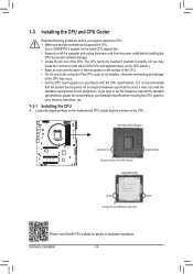
LGA1200 CPU Socket Alignment Key Pin One Corner of the CPU. Locate the alignment keys on the motherboard CPU socket and the notches on the CPU Please visit GIGABYTE's website for the peripherals. Hardware Installation - 14 - The CPU cannot be set the frequency beyond hardware ...specifications since it does not meet the standard requirements for details on hardware installation. It is not recommended that the motherboard supports the CPU. (Go to GIGABYTE's website for the latest CPU support list.) •• Always turn on the computer if the CPU cooler is...
LGA1200 CPU Socket Alignment Key Pin One Corner of the CPU. Locate the alignment keys on the motherboard CPU socket and the notches on the CPU Please visit GIGABYTE's website for the peripherals. Hardware Installation - 14 - The CPU cannot be set the frequency beyond hardware ...specifications since it does not meet the standard requirements for details on hardware installation. It is not recommended that the motherboard supports the CPU. (Go to GIGABYTE's website for the latest CPU support list.) •• Always turn on the computer if the CPU cooler is...
User Manual
Page 15
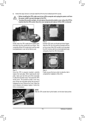
... the CPU into position. The protective plastic cover may align the CPU notches with the socket alignment keys) and gently insert the CPU into the motherboard CPU socket. • Before installing the CPU, make sure the front end of the CPU. Save the cover properly and replace it when the CPU...
... the CPU into position. The protective plastic cover may align the CPU notches with the socket alignment keys) and gently insert the CPU into the motherboard CPU socket. • Before installing the CPU, make sure the front end of the CPU. Save the cover properly and replace it when the CPU...
User Manual
Page 16
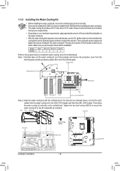
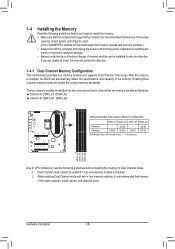
...: Screw Number M2*6 2 M3*10.8 M3*11.5 M2.5*5 4 3 4 Refer to the pictures below to install the water cooling kit on the motherboard. cables from the thermal pads. Inlet Outlet LED_CPU LED_CPU Short Screw (M2*6) LED_PCH LED_PCH Hardware Installation - 16 - Thermal Paste Thermal Pad Thermal Pad Thermal...kit out of the provided thermal paste on the water cooling kit. •• After the water cooling kit is placed on the motherboard, use the OC Ignition button to the M.2 standoffs as indicated below . Then unplug the power supply and tighten the screws included ...
...: Screw Number M2*6 2 M3*10.8 M3*11.5 M2.5*5 4 3 4 Refer to the pictures below to install the water cooling kit on the motherboard. cables from the thermal pads. Inlet Outlet LED_CPU LED_CPU Short Screw (M2*6) LED_PCH LED_PCH Hardware Installation - 16 - Thermal Paste Thermal Pad Thermal Pad Thermal...kit out of the provided thermal paste on the water cooling kit. •• After the water cooling kit is placed on the motherboard, use the OC Ignition button to the M.2 standoffs as indicated below . Then unplug the power supply and tighten the screws included ...

User Manual
Page 17
... above, connect your water cooling components. Then tighten the four short screws (M2.5*5) and washers (Note) to be installed on both sides of the motherboard. - 17 - Make sure the water cooling kit is securely attached. Hardware Installation Long Screw Washer (M3*11.5) Short Screw Washer (M2.5*5) (Note...) The washers need to their corresponding holes. Step 3: Carefully flip the motherboard over, fasten the CPU backplate using the four long screws (M3*10.8) and washers (Note) in a diagonal sequence as indicated.
... above, connect your water cooling components. Then tighten the four short screws (M2.5*5) and washers (Note) to be installed on both sides of the motherboard. - 17 - Make sure the water cooling kit is securely attached. Hardware Installation Long Screw Washer (M3*11.5) Short Screw Washer (M2.5*5) (Note...) The washers need to their corresponding holes. Step 3: Carefully flip the motherboard over, fasten the CPU backplate using the four long screws (M3*10.8) and washers (Note) in a diagonal sequence as indicated.
User Manual
Page 18
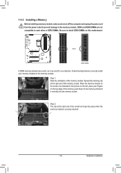
...the memory: •• Make sure that memory of the same capacity, brand, speed, and chips be used . (Go to GIGABYTE's website for the latest supported memory speeds and memory modules.) •• Always turn off the computer and unplug the power cord ...two memory sockets as following guidelines before installing the memory to insert the memory, switch the direction. 1-4-1 Dual Channel Memory Configuration This motherboard provides four memory sockets and supports Dual Channel Technology. Hardware Installation - 18 - The four memory sockets are unable to prevent hardware...
...the memory: •• Make sure that memory of the same capacity, brand, speed, and chips be used . (Go to GIGABYTE's website for the latest supported memory speeds and memory modules.) •• Always turn off the computer and unplug the power cord ...two memory sockets as following guidelines before installing the memory to insert the memory, switch the direction. 1-4-1 Dual Channel Memory Configuration This motherboard provides four memory sockets and supports Dual Channel Technology. Hardware Installation - 18 - The four memory sockets are unable to prevent hardware...
User Manual
Page 19
..., make sure to turn off the computer and unplug the power cord from the power outlet to prevent damage to install DDR4 DIMMs on this motherboard. DDR4 and DDR3 DIMMs are not compatible to each other or DDR2 DIMMs. Be sure to the memory module. Hardware Installation Place the memory module...
..., make sure to turn off the computer and unplug the power cord from the power outlet to prevent damage to install DDR4 DIMMs on this motherboard. DDR4 and DDR3 DIMMs are not compatible to each other or DDR2 DIMMs. Be sure to the memory module. Hardware Installation Place the memory module...
User Manual
Page 20
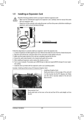
... the expansion slot. 1. Remove the metal slot cover from the power outlet before you begin to install an expansion card: •• Make sure the motherboard supports the expansion card. After installing all expansion cards, replace the chassis cover(s). 6. Carefully read the manual that supports your operating system. Secure the card...
... the expansion slot. 1. Remove the metal slot cover from the power outlet before you begin to install an expansion card: •• Make sure the motherboard supports the expansion card. After installing all expansion cards, replace the chassis cover(s). 6. Carefully read the manual that supports your operating system. Secure the card...
User Manual
Page 21
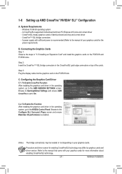
... Settings and ensure AMD CrossFire is enabled. (Note) The bridge connector(s) may differ by graphics cards and driver version. Refer to On. A CrossFire/SLI-supported motherboard with sufficient power is recommended (Refer to the Configure SLI, Surround, Physx screen and ensure Maximize 3D performance is set to the manual that came...
... Settings and ensure AMD CrossFire is enabled. (Note) The bridge connector(s) may differ by graphics cards and driver version. Refer to On. A CrossFire/SLI-supported motherboard with sufficient power is recommended (Refer to the Configure SLI, Surround, Physx screen and ensure Maximize 3D performance is set to the manual that came...
User Manual
Page 22
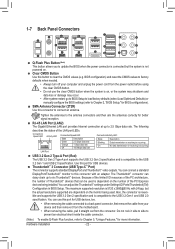
.... BIOS configuration) and reset the CMOS values to factory defaults when needed. •• Always turn off your device and then remove it from the motherboard. •• When removing the cable, pull it straight out from the power outlet before using the clear CMOS button. •• Do not use...
.... BIOS configuration) and reset the CMOS values to factory defaults when needed. •• Always turn off your device and then remove it from the motherboard. •• When removing the cable, pull it straight out from the power outlet before using the clear CMOS button. •• Do not use...
User Manual
Page 24
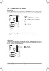
... 1 23 _ _ Before setting the SB switch, be sure to turn on/off your computer and power supply. 1 23 U __ 3 S_ _ _B __ 3 Quick Buttons This motherboard has 2 quick buttons: power button and reset button. The power button and reset button allow users to quickly turn off or reset the computer in...
... 1 23 _ _ Before setting the SB switch, be sure to turn on/off your computer and power supply. 1 23 U __ 3 S_ _ _B __ 3 Quick Buttons This motherboard has 2 quick buttons: power button and reset button. The power button and reset button allow users to quickly turn off or reset the computer in...
User Manual
Page 25
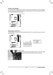
... OC button helps enthusiasts and overclockers not only get the most performance from their hardware, but also the absolute most optimized GIGABYTE overclocking configuration for your hardware. You can employ following motherboard voltages. S S_ S_ S_ S_ S_ S_ S_ S_ S_ _ S FS_ Hardware Installation BBBB Definition 1 power 2 GND S S3 S3 S3...
... OC button helps enthusiasts and overclockers not only get the most performance from their hardware, but also the absolute most optimized GIGABYTE overclocking configuration for your hardware. You can employ following motherboard voltages. S S_ S_ S_ S_ S_ S_ S_ S_ S_ _ S FS_ Hardware Installation BBBB Definition 1 power 2 GND S S3 S3 S3...
User Manual
Page 26
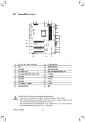
...) SATA3 0/1/2/3/4/5 14) M2A_CPU/M2M_PCH/M2P_PCH 15) F_PANEL 16) F_AUDIO 17) F_U32C 18) F_U32 19) F_USB 20) BAT Read the following guidelines before turning on the motherboard.
...) SATA3 0/1/2/3/4/5 14) M2A_CPU/M2M_PCH/M2P_PCH 15) F_PANEL 16) F_AUDIO 17) F_U32C 18) F_U32 19) F_USB 20) BAT Read the following guidelines before turning on the motherboard.
User Manual
Page 27
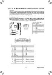
... the power supply is not connected, the computer will not start. If the 12V power connector is turned off and all the components on the motherboard. B B_ 5 8 1 4 ATX_12V_2X4_1/ ATX_12V_2X4_2 _3 ATX_12V_2X4_1/ATX_12V_2X4_2: Pin No. The power connector possesses a foolproof design. Connect the power supply cable to the CPU. _ _B _ S_ _F...
... the power supply is not connected, the computer will not start. If the 12V power connector is turned off and all the components on the motherboard. B B_ 5 8 1 4 ATX_12V_2X4_1/ ATX_12V_2X4_2 _3 ATX_12V_2X4_1/ATX_12V_2X4_2: Pin No. The power connector possesses a foolproof design. Connect the power supply cable to the CPU. _ _B _ S_ _F...


