

Owners Manual
Page 2
AVR 325 AUDIO/VIDEO RECEIVER 3 Introduction 4 Important Safety Information 4 Unpacking 5 Front-Panel Controls 7 Front-Panel Information Display 8 Rear-Panel Connections 11 Main Remote Control Functions 14 Zone ...-Through 39 Transport Control Punch-Through 39 Reassigning Device Control Selectors 39 Resetting the Remote Memory 40 Function List 42 Setup Code Tables 54 Troubleshooting Guide 54 Processor Reset 55 Technical Specifications See trademark acknowledgements on the Zone II remote 2 TABLE OF CONTENTS EXAMPLE - (bold type) indicates a specific remote control or...
AVR 325 AUDIO/VIDEO RECEIVER 3 Introduction 4 Important Safety Information 4 Unpacking 5 Front-Panel Controls 7 Front-Panel Information Display 8 Rear-Panel Connections 11 Main Remote Control Functions 14 Zone ...-Through 39 Transport Control Punch-Through 39 Reassigning Device Control Selectors 39 Resetting the Remote Memory 40 Function List 42 Setup Code Tables 54 Troubleshooting Guide 54 Processor Reset 55 Technical Specifications See trademark acknowledgements on the Zone II remote 2 TABLE OF CONTENTS EXAMPLE - (bold type) indicates a specific remote control or...

Owners Manual
Page 12
...press one of these buttons to scroll through the process of programming the remote or learning commands from the factory to operate the AVR 325 and most Harman Kardon CD or DVD players and cassette decks. c Program/SPL Indicator: This three-color indicator is pressed, use to start the ...process of the Input Selectors e. Once this button is used to guide you must press the AVR Selector Button f again to operate the AVR 325's functions with the ...
...press one of these buttons to scroll through the process of programming the remote or learning commands from the factory to operate the AVR 325 and most Harman Kardon CD or DVD players and cassette decks. c Program/SPL Indicator: This three-color indicator is pressed, use to start the ...process of the Input Selectors e. Once this button is used to guide you must press the AVR Selector Button f again to operate the AVR 325's functions with the ...

Owners Manual
Page 29
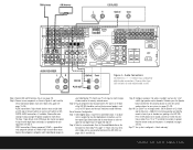
...this option. DTS: When the green LED next to the AVR 325. When a disc does offer multiple soundtrack choices, you that is being received. See page 20 for recording compressed audio files. Consult the program guide that some cases, the previews of special material will only be...There are recorded with either level of compression using the menus to determine which type of digital data stream is present, the AVR 325 uses display indicators to accommodate it will allow the appropriate surround sources to DTS decoding, and Dolby Digital bitstreams will automatically be...
...this option. DTS: When the green LED next to the AVR 325. When a disc does offer multiple soundtrack choices, you that is being received. See page 20 for recording compressed audio files. Consult the program guide that some cases, the previews of special material will only be...There are recorded with either level of compression using the menus to determine which type of digital data stream is present, the AVR 325 uses display indicators to accommodate it will allow the appropriate surround sources to DTS decoding, and Dolby Digital bitstreams will automatically be...
Owners Manual
Page 31
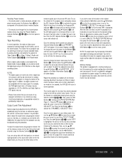
...digital and analog surround mode. When it is too low. Once the reference level has been set . First, set the reference volume for the AVR 325 is established using program material such as outlined on -screen › cursor so that it is red the level is next to the CHANNEL ... copy. For example, the PCM digital input from which time all adjustments have different trim levels for listening through the list of the remote to guide you wish to adjust. To adjust the subwoofer level, press the ⁄/¤ Buttons n until all the levels to their original factory default...
...digital and analog surround mode. When it is too low. Once the reference level has been set . First, set the reference volume for the AVR 325 is established using program material such as outlined on -screen › cursor so that it is red the level is next to the CHANNEL ... copy. For example, the PCM digital input from which time all adjustments have different trim levels for listening through the list of the remote to guide you wish to adjust. To adjust the subwoofer level, press the ⁄/¤ Buttons n until all the levels to their original factory default...
Owners Manual
Page 40
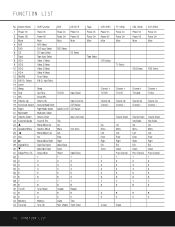
Ch. 32 1 33 2 34 3 35 4 36 5 37 6 38 7 39 8 40 Tun-M 41 9 42 0 43 Memory 44 Tune Up AVR Function Power On Power Off Mute AVR Select DVD Input Select CD Input Select Tape Input Select Video 1 Select Video 2 Select Video 3 Select Video 4 Select Tuner Select 6/8 Ch. Input Select DVD Power ... Channel - Select 14 Learn 15 Sleep 16 Test 17 SPL 18 Volume Up 19 Surround Select 20 Night 21 Multiroom 22 Volume Down 23 Channel/Guide 24 ⁄ 25 Speaker/Menu 26 fi 27 Set 28 fl 29 Digital/Exit 30 ¤ 31 Delay/Prev. Volume Up Channel - FUNCTION LIST No...
Ch. 32 1 33 2 34 3 35 4 36 5 37 6 38 7 39 8 40 Tun-M 41 9 42 0 43 Memory 44 Tune Up AVR Function Power On Power Off Mute AVR Select DVD Input Select CD Input Select Tape Input Select Video 1 Select Video 2 Select Video 3 Select Video 4 Select Tuner Select 6/8 Ch. Input Select DVD Power ... Channel - Select 14 Learn 15 Sleep 16 Test 17 SPL 18 Volume Up 19 Surround Select 20 Night 21 Multiroom 22 Volume Down 23 Channel/Guide 24 ⁄ 25 Speaker/Menu 26 fi 27 Set 28 fl 29 Digital/Exit 30 ¤ 31 Delay/Prev. Volume Up Channel - FUNCTION LIST No...
Owners Manual
Page 51
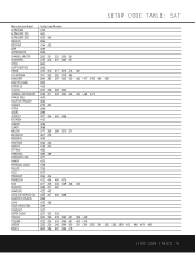
... PRESIDENT PRIMESTAR RCA REALISTIC SAMSUNG SATELLITE SERVICE CO SCIENTIFIC ATLANTA SONY STAR CHOICE DBS STARCAST SUPER GUIDE TEECOM TOSHIBA UNIDEN ZENITH Setup Code Number 472 450 422 442 356 414 425 359 359 320 321 322 325 361 315 316 319 380 451 360 356 312 313 317 318 413 481 331...
... PRESIDENT PRIMESTAR RCA REALISTIC SAMSUNG SATELLITE SERVICE CO SCIENTIFIC ATLANTA SONY STAR CHOICE DBS STARCAST SUPER GUIDE TEECOM TOSHIBA UNIDEN ZENITH Setup Code Number 472 450 422 442 356 414 425 359 359 320 321 322 325 361 315 316 319 380 451 360 356 312 313 317 318 413 481 331...

Owners Manual
Page 54
... • Resume play for these steps do not solve the problem, consult an authorized Harman Kardon service center. 54 TROUBLESHOOTING GUIDE NOTE: Resetting the processor will be reentered. TROUBLESHOOTING GUIDE SYMPTOM Unit does not function when Main Power Switch is pushed Display lights, but front panel...presets. Next, press and hold the Surround Mode 7 and the Tuner Mode Selector ^ buttons for three seconds. To clear the AVR 325's entire system memory including tuner presets, output level settings, delay times and speaker configuration data, first put the unit in Standby...
... • Resume play for these steps do not solve the problem, consult an authorized Harman Kardon service center. 54 TROUBLESHOOTING GUIDE NOTE: Resetting the processor will be reentered. TROUBLESHOOTING GUIDE SYMPTOM Unit does not function when Main Power Switch is pushed Display lights, but front panel...presets. Next, press and hold the Surround Mode 7 and the Tuner Mode Selector ^ buttons for three seconds. To clear the AVR 325's entire system memory including tuner presets, output level settings, delay times and speaker configuration data, first put the unit in Standby...

Quick Start Guide
Page 1
... pages referenced in the listening room (see page 8). SPEAKER PLACEMENT This Quick-Start Guide will help you for purchasing a Harman Kardon AVR 325. Figure 1 - Place your source equipment or speakers. AVR 325 QUICK-START GUIDE FRONT LEFT SPEAKER (White) CENTER SPEAKER (Green) FRONT RIGHT SPEAKER (Red) SURROUND...for complete details on how to install, configure and operate the AVR 325, as well as for each speaker correspond to the matching output terminal connection on your speakers in this guide. The colors are standardized, but not all equipment or connectors ...
... pages referenced in the listening room (see page 8). SPEAKER PLACEMENT This Quick-Start Guide will help you for purchasing a Harman Kardon AVR 325. Figure 1 - Place your source equipment or speakers. AVR 325 QUICK-START GUIDE FRONT LEFT SPEAKER (White) CENTER SPEAKER (Green) FRONT RIGHT SPEAKER (Red) SURROUND...for complete details on how to install, configure and operate the AVR 325, as well as for each speaker correspond to the matching output terminal connection on your speakers in this guide. The colors are standardized, but not all equipment or connectors ...
Quick Start Guide
Page 2
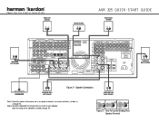
... Binding-Post Speaker Terminal Figure 3 - Connect the speakers to the receiver: red (+) on speaker to black (-) (see page 15). FRONT LEFT SPEAKER + _ CENTER SPEAKER + _ AVR 325 QUICK-START GUIDE FRONT RIGHT SPEAKER + _ + _ SURROUND LEFT SPEAKER + _ SURROUND RIGHT SPEAKER LINE IN/SUB/LFE SUBWOOFER + _ SURROUND BACK LEFT SPEAKER Figure 2 - Speaker Connections + _ SURROUND BACK RIGHT...
... Binding-Post Speaker Terminal Figure 3 - Connect the speakers to the receiver: red (+) on speaker to black (-) (see page 15). FRONT LEFT SPEAKER + _ CENTER SPEAKER + _ AVR 325 QUICK-START GUIDE FRONT RIGHT SPEAKER + _ + _ SURROUND LEFT SPEAKER + _ SURROUND RIGHT SPEAKER LINE IN/SUB/LFE SUBWOOFER + _ SURROUND BACK LEFT SPEAKER Figure 2 - Speaker Connections + _ SURROUND BACK RIGHT...
Quick Start Guide
Page 3
...see pages 24-25). Basic Receiver Configuration Step 7. ment is needed . Configure speakers: No action is needed if you at shoulder level, pointing at the AVR 325. Step 10. Press "5" or "7" to Coax 1, no adjust- sit back and enjoy! Assign the other modes later as appropriate for your TV set... products, such as shown in front of this guide (see pages 20-21 and 26-29.) Step 9. DIGITAL AUDIO connections, if available: Choose either type (but may select other digital inputs and outputs as you become familiar with the AVR 325; Plug all components into AC power outlets. The...
...see pages 24-25). Basic Receiver Configuration Step 7. ment is needed . Configure speakers: No action is needed if you at shoulder level, pointing at the AVR 325. Step 10. Press "5" or "7" to Coax 1, no adjust- sit back and enjoy! Assign the other modes later as appropriate for your TV set... products, such as shown in front of this guide (see pages 20-21 and 26-29.) Step 9. DIGITAL AUDIO connections, if available: Choose either type (but may select other digital inputs and outputs as you become familiar with the AVR 325; Plug all components into AC power outlets. The...