
HP DesignJet 3000/3500 CP Printer User’s Guide - C4724-90051
Page 5
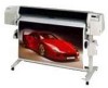
... Take up reel Make selections in this guide. •Page 8-5, Viewing the Current Configuration of this manual. iii Install the printer Connect the printer Choose media Load media Load the Take Up Reel Replace ink system components See the printer's current configuration Turning on the Take Up Reel •Page 2-14, Navigating the Menu System...
... Take up reel Make selections in this guide. •Page 8-5, Viewing the Current Configuration of this manual. iii Install the printer Connect the printer Choose media Load media Load the Take Up Reel Replace ink system components See the printer's current configuration Turning on the Take Up Reel •Page 2-14, Navigating the Menu System...
HP DesignJet 3000/3500 CP Printer User’s Guide - C4724-90051
Page 22
...applications include their own drivers. Throughout this manual, references to "PostScript files" mean files sent to the printer using the HP DesignJet PostScript driver supplied with this printer for the combination of drivers are also faster than HP-GL/2 or PostScript® Windows™... they contain as opposed to print from AutoCAD. If you install and use the information they are supplied with the 3500CP printer: s HP DesignJet PostScript® drivers for Macintosh® (QuickDraw™) s HP DesignJet PostScript® drivers for Microsoft® Windows™ applications ...
...applications include their own drivers. Throughout this manual, references to "PostScript files" mean files sent to the printer using the HP DesignJet PostScript driver supplied with this printer for the combination of drivers are also faster than HP-GL/2 or PostScript® Windows™... they contain as opposed to print from AutoCAD. If you install and use the information they are supplied with the 3500CP printer: s HP DesignJet PostScript® drivers for Macintosh® (QuickDraw™) s HP DesignJet PostScript® drivers for Microsoft® Windows™ applications ...

Service Manual
Page 12
...which normally includes all of the product. A connection to cut yourself on the encoder strip inside the plotter. x Contents HP DesignJet CP Series Printers Protective conductor terminal. For protection against electrical shock in case of a fault. Used with this symbol must also be ...adhered to ground before operating the equipment. Used for the user to refer to the instruction manual in order to protect against damage to ground in the manner described in the installation (operating) manual, and before operating equipment. Frame or chassis terminal. C A U T I ĂN&#...
...which normally includes all of the product. A connection to cut yourself on the encoder strip inside the plotter. x Contents HP DesignJet CP Series Printers Protective conductor terminal. For protection against electrical shock in case of a fault. Used with this symbol must also be ...adhered to ground before operating the equipment. Used for the user to refer to the instruction manual in order to protect against damage to ground in the manner described in the installation (operating) manual, and before operating equipment. Frame or chassis terminal. C A U T I ĂN&#...

Service Manual
Page 238
...Manually slide the carriage assembly to the middle of the Service Station Flag. 1. Loosen the remaining three TĆ20 screws (item 4) securing the service station to the User Guide). Removal of the printer...to the primer removal procedure ' page 8Ć29. 8-26 HP DesignJet CP Series Printers Removal and Installation These screws are long and can then be reached by lifting... Cover ' page 8Ć21. 3. WARNING Switch off the printer and remove the power cord. 2. Remove the following 1. Note for HP DesignJets 3500CP/3000CP: Make sure you . Position the flag horizontal and push...
...Manually slide the carriage assembly to the middle of the Service Station Flag. 1. Loosen the remaining three TĆ20 screws (item 4) securing the service station to the User Guide). Removal of the printer...to the primer removal procedure ' page 8Ć29. 8-26 HP DesignJet CP Series Printers Removal and Installation These screws are long and can then be reached by lifting... Cover ' page 8Ć21. 3. WARNING Switch off the printer and remove the power cord. 2. Remove the following 1. Note for HP DesignJets 3500CP/3000CP: Make sure you . Position the flag horizontal and push...

Service Manual
Page 241
... three TĆ15 screws (item 2) securing the Primer Assembly (item 3) to HP DesignJets 2500CP/2000CP) NOTE FOR HP DESIGNJETS 3500CP/3000CP: IF THE PRIMER ASSEMBLY FAILS, YOU MUST REPLACE THE COMPLETE SERVICE STATION. Window...Manually slide the carriage assembly to figure 9 ' page 8Ć31 Removal WARNING Switch off the printer and remove the power cord. 1. Release the cables from the position J4 PRIMER SENSOR on the service station interconnect PCA. 7. Refer to the middle of the printer. 3. Remove the primer assembly. 8-29 HP DesignJet CP Series Printers Removal and Installation...
... three TĆ15 screws (item 2) securing the Primer Assembly (item 3) to HP DesignJets 2500CP/2000CP) NOTE FOR HP DESIGNJETS 3500CP/3000CP: IF THE PRIMER ASSEMBLY FAILS, YOU MUST REPLACE THE COMPLETE SERVICE STATION. Window...Manually slide the carriage assembly to figure 9 ' page 8Ć31 Removal WARNING Switch off the printer and remove the power cord. 1. Release the cables from the position J4 PRIMER SENSOR on the service station interconnect PCA. 7. Refer to the middle of the printer. 3. Remove the primer assembly. 8-29 HP DesignJet CP Series Printers Removal and Installation...

Service Manual
Page 245
.... Top Cover and Window ' page 8Ć15. 9. Removal and Installation HP DesignJet CP Series Printers 8-33 Route the encoder strip (item 7) through the grounding bridge (item 3). 6. Install the left side of the printer. 2. Check the encoder strip does not touch the encoder sensor in ...encoder strip (item 6) has sharp edges and could cause injury. Install two TĆ15 screws (item 2) through the encoder sensor in the carriage assembly. Manually slide the carriage assembly along the printer. Installation WARNING Care should be taken while performing the following : 1. Caution...
.... Top Cover and Window ' page 8Ć15. 9. Removal and Installation HP DesignJet CP Series Printers 8-33 Route the encoder strip (item 7) through the grounding bridge (item 3). 6. Install the left side of the printer. 2. Check the encoder strip does not touch the encoder sensor in ...encoder strip (item 6) has sharp edges and could cause injury. Install two TĆ15 screws (item 2) through the encoder sensor in the carriage assembly. Manually slide the carriage assembly along the printer. Installation WARNING Care should be taken while performing the following : 1. Caution...

Service Manual
Page 248
Right Hand Cover ' page 8Ć21 2. Remove the trailing cable from the 3 cable clamps at the rear of the printer. 8-36 HP DesignJet CP Series Printers Removal and Installation J5 DATA 3. Remove the trailing cable from connectors on the carriage PCA. 4. Pull the trailing cable through a hole in the...it through the ferrite (item 7) at the rear of the printer. 3. Remove the trailing cable from the following : 1. Manually slide the carriage assembly to figure 12 ' page 8Ć38 Removal WARNING Switch off the printer and remove the power cord. 1. Disconnect the trailing cable ...
Right Hand Cover ' page 8Ć21 2. Remove the trailing cable from the 3 cable clamps at the rear of the printer. 8-36 HP DesignJet CP Series Printers Removal and Installation J5 DATA 3. Remove the trailing cable from connectors on the carriage PCA. 4. Pull the trailing cable through a hole in the...it through the ferrite (item 7) at the rear of the printer. 3. Remove the trailing cable from the following : 1. Manually slide the carriage assembly to figure 12 ' page 8Ć38 Removal WARNING Switch off the printer and remove the power cord. 1. Disconnect the trailing cable ...

Service Manual
Page 251
Left Hand Cover ' page 8Ć18. The rest of the YĆaxis tensioner holder (item 2). Removal and Installation HP DesignJet CP Series Printers 8-39 Remove the carriage assembly ' page 8Ć42 7. Caution: Cup your hand over the YĆaxis tensioner holder in the YĆ...axis tensioner holder. 5. To release the tension on the YĆaxis belt (item 3), manually squeeze the spring (item 1) using the tensioner wedge clip (item ...
Left Hand Cover ' page 8Ć18. The rest of the YĆaxis tensioner holder (item 2). Removal and Installation HP DesignJet CP Series Printers 8-39 Remove the carriage assembly ' page 8Ć42 7. Caution: Cup your hand over the YĆaxis tensioner holder in the YĆ...axis tensioner holder. 5. To release the tension on the YĆaxis belt (item 3), manually squeeze the spring (item 1) using the tensioner wedge clip (item ...

Service Manual
Page 264
.... 7. Window and Top Cover ' page 8Ć15. 2. This can be necessary to the left hand side chassis, it towards you. 8-52 HP DesignJet CP Series Printers Removal and Installation Disconnect the elevator stepper motor cable from position J9 ELEV STEPPER on the refill interconnect PCA and release from the cable clamp. 8. Elevator... assembly (item 3) by turning the motor gear under the elevator assembly. 3. Loosen the three TĆ20 screws (item 2) securing the elevator assembly to manually raise the elevator assembly. Left Hand Cover ' page 8Ć18. Remove the following: 1.
.... 7. Window and Top Cover ' page 8Ć15. 2. This can be necessary to the left hand side chassis, it towards you. 8-52 HP DesignJet CP Series Printers Removal and Installation Disconnect the elevator stepper motor cable from position J9 ELEV STEPPER on the refill interconnect PCA and release from the cable clamp. 8. Elevator... assembly (item 3) by turning the motor gear under the elevator assembly. 3. Loosen the three TĆ20 screws (item 2) securing the elevator assembly to manually raise the elevator assembly. Left Hand Cover ' page 8Ć18. Remove the following: 1.

Service Manual
Page 270
... left side first, then install the bail assembly into the bail assembly (item 1). 2. Close the window. 4. Bail Assembly and Star Wheel Assemblies Refer to the left and right hand side chassis. 4. Open the window. 2. Manually move the drive roller around. 5. Lifting up the...release it from holes in the left . Install the bail assembly by pushing together the retaining clips and pulling them off Installation 1. Perform D11 Bail Service Test ' page 4Ć23 8-58 HP DesignJet CP Series Printers Removal and Installation Install the star wheel assemblies (item 2) by pushing...
... left side first, then install the bail assembly into the bail assembly (item 1). 2. Close the window. 4. Bail Assembly and Star Wheel Assemblies Refer to the left and right hand side chassis. 4. Open the window. 2. Manually move the drive roller around. 5. Lifting up the...release it from holes in the left . Install the bail assembly by pushing together the retaining clips and pulling them off Installation 1. Perform D11 Bail Service Test ' page 4Ć23 8-58 HP DesignJet CP Series Printers Removal and Installation Install the star wheel assemblies (item 2) by pushing...

Service Manual
Page 281
.... 2. Remove the drive roller (item 10) by removing the retaining clip (item 3). 7. Removal and Installation HP DesignJet CP Series Printers 8-69 Right Hand Cover ' page 8Ć21. 4. Remove the top half of the printer. 3. Remove the clutch (item 4) and washers (item 5) on the right, then sliding to the left... Drive Roller (Only Applicable to HP DesignJets 2500CP and 2000CP) Refer to the up and to the left end of the overdrive shaft by holding the ends and lifting out. Remove the following : 1. Left Hand Cover ' page 8Ć18. 3. Manually slide the carriage assembly to the...
.... 2. Remove the drive roller (item 10) by removing the retaining clip (item 3). 7. Removal and Installation HP DesignJet CP Series Printers 8-69 Right Hand Cover ' page 8Ć21. 4. Remove the top half of the printer. 3. Remove the clutch (item 4) and washers (item 5) on the right, then sliding to the left... Drive Roller (Only Applicable to HP DesignJets 2500CP and 2000CP) Refer to the up and to the left end of the overdrive shaft by holding the ends and lifting out. Remove the following : 1. Left Hand Cover ' page 8Ć18. 3. Manually slide the carriage assembly to the...

Service Manual
Page 284
...hand side chassis. 8. Service Station Assembly ' page 8Ć26. 8-72 HP DesignJet CP Series Printers Removal and Installation Window and Top Cover ' page 8Ć15. 2. Remove the roller support bracket (item 2). 6. Manually slide the carriage assembly to the left hand side chassis. 5. Remove the ...overdrive assembly (item 9) to figure 25B ' page 8Ć75 WARNING Switch off the printer and remove the power cord. 1. Overdrive Assembly and Drive Roller (Only Applicable to HP DesignJets 3500CP and 3000CP) Refer to the left and right hand side chassis. Remove the four ...
...hand side chassis. 8. Service Station Assembly ' page 8Ć26. 8-72 HP DesignJet CP Series Printers Removal and Installation Window and Top Cover ' page 8Ć15. 2. Remove the roller support bracket (item 2). 6. Manually slide the carriage assembly to the left hand side chassis. 5. Remove the ...overdrive assembly (item 9) to figure 25B ' page 8Ć75 WARNING Switch off the printer and remove the power cord. 1. Overdrive Assembly and Drive Roller (Only Applicable to HP DesignJets 3500CP and 3000CP) Refer to the left and right hand side chassis. Remove the four ...

Service Manual
Page 308
... an area of this Service Manual as a guide to clean the electrical contacts and is called the Ink Cleaner (Part Number C6247A Ć includes the instructions). If the printer is assigned to print more frequently. Use the Removal and Installation Chapter of 0.76 m2/print... Ć ensuring a good performance during all the product life. One of the design. When the printer exceeds 7,500,000 passes (HP DesignJets 2500CP/2000CP) or 6,500,000 passes (HP DesignJets 3500CP/300CP), the front panel displays the following message: Maintenance Advised" The Service Print also conveys the ...
... an area of this Service Manual as a guide to clean the electrical contacts and is called the Ink Cleaner (Part Number C6247A Ć includes the instructions). If the printer is assigned to print more frequently. Use the Removal and Installation Chapter of 0.76 m2/print... Ć ensuring a good performance during all the product life. One of the design. When the printer exceeds 7,500,000 passes (HP DesignJets 2500CP/2000CP) or 6,500,000 passes (HP DesignJets 3500CP/300CP), the front panel displays the following message: Maintenance Advised" The Service Print also conveys the ...


