
User Guide
Page 1
Getting Started
Getting Started

User Guide
Page 2
... change without the prior written consent of June 2007. Wi-Fi CERTIFIED 802.11n based on equipment that is intended for home and other limited viewing uses only unless otherwise authorized by copyright. No part of this document may affect the ability of...property rights. Reverse engineering or disassembly is not furnished by HP. Box 4010 Cupertino, CA 95015-4010 USA © Copyright 2000-2009 Hewlett-Packard Development Company, L.P. Hewlett-Packard Company P.O. Microsoft, the Windows logo, and Windows are trademarks or registered trademarks of the Microsoft group of the...
... change without the prior written consent of June 2007. Wi-Fi CERTIFIED 802.11n based on equipment that is intended for home and other limited viewing uses only unless otherwise authorized by copyright. No part of this document may affect the ability of...property rights. Reverse engineering or disassembly is not furnished by HP. Box 4010 Cupertino, CA 95015-4010 USA © Copyright 2000-2009 Hewlett-Packard Development Company, L.P. Hewlett-Packard Company P.O. Microsoft, the Windows logo, and Windows are trademarks or registered trademarks of the Microsoft group of the...
User Guide
Page 3
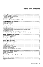
... 25 Accessing Support on the Web 25 Finding Guides on the Web 25 Finding Onscreen Guides 26 Using the PC Help & Tools Folder 26 Using HP Advisor Software 26 Using the Computer with Safety and Comfort 27 Troubleshooting and Maintenance 29 Troubleshooting Computer Problems 29 Software Troubleshooting 45 Maintenance ...48 Keeping...
... 25 Accessing Support on the Web 25 Finding Guides on the Web 25 Finding Onscreen Guides 26 Using the PC Help & Tools Folder 26 Using HP Advisor Software 26 Using the Computer with Safety and Comfort 27 Troubleshooting and Maintenance 29 Troubleshooting Computer Problems 29 Software Troubleshooting 45 Maintenance ...48 Keeping...

User Guide
Page 4
iv Getting Started (features vary by model)
iv Getting Started (features vary by model)

User Guide
Page 5
Setting Up Your Computer WARNING: The power supply is out of serious injury, read "Safety Notices" in a walkway or where it can increase the inside temperature, causing fire, trouble, and electrification. See "Preparing to the electrical power system. All cabling is preset for the first time and complete the initial setup. It also provides important electrical and mechanical safety information. WARNING: Place the computer in an appropriate location so that: All ventilation openings are unobstructed. These can be stepped on or damaged from water, dust, moisture, and soot. ...
Setting Up Your Computer WARNING: The power supply is out of serious injury, read "Safety Notices" in a walkway or where it can increase the inside temperature, causing fire, trouble, and electrification. See "Preparing to the electrical power system. All cabling is preset for the first time and complete the initial setup. It also provides important electrical and mechanical safety information. WARNING: Place the computer in an appropriate location so that: All ventilation openings are unobstructed. These can be stepped on or damaged from water, dust, moisture, and soot. ...

User Guide
Page 6
Connect the television cable or the telephone line cord to the inputs and outputs of the computer or on the computer may vary. Power cord and devices Icon/label Description and function Power connector. NOTE: The location, availability, and number of connectors on the front of the computer. Look in the computer box for mouse, keyboard, digital cameras, or other devices to the computer Some peripheral devices can plug into connectors on the back of the surge protection device and then to a power surge protection device. Protect the monitor, computer, and connected accessories by ...
Connect the television cable or the telephone line cord to the inputs and outputs of the computer or on the computer may vary. Power cord and devices Icon/label Description and function Power connector. NOTE: The location, availability, and number of connectors on the front of the computer. Look in the computer box for mouse, keyboard, digital cameras, or other devices to the computer Some peripheral devices can plug into connectors on the back of the surge protection device and then to a power surge protection device. Protect the monitor, computer, and connected accessories by ...

User Guide
Page 7
Network Icon/label ETHERNET Description and function Ethernet LAN connector to connect to a TV or monitor. Digital video output connector (select models only), to connect to an Ethernet (RJ-45) local area network (LAN) hub or any broadband connection. VGA/Monitor VGA/Monitor (blue) display output connector, to connect to the computer. HDMI-DVI HDMI-to-DVI adapter, to adapt a TV or a monitor video cable so it can connect to a VGA monitor. You may need to use an HDMI-to-DVI adapter to connect a display with only a DVI connector to the computer. VGA-DVI VGA-to-...
Network Icon/label ETHERNET Description and function Ethernet LAN connector to connect to a TV or monitor. Digital video output connector (select models only), to connect to an Ethernet (RJ-45) local area network (LAN) hub or any broadband connection. VGA/Monitor VGA/Monitor (blue) display output connector, to connect to the computer. HDMI-DVI HDMI-to-DVI adapter, to adapt a TV or a monitor video cable so it can connect to a VGA monitor. You may need to use an HDMI-to-DVI adapter to connect a display with only a DVI connector to the computer. VGA-DVI VGA-to-...

User Guide
Page 8
Audio connectors Icon/label Description and function Audio Line Out (lime green) to connect Center/Subwoofer speakers in a multichannel audio configuration. Line C/Sub (gold) connector to connect front left and front right analog speakers. Your computer model may vary. Line Rear (black) connector to the Web support page for your model; Audio connectors are stereo mini-jacks that may be included with the monitor. For detailed instructions about how to connect and configure other multichannel speakers, go to connect rear speakers in a multichannel audio configuration. May...
Audio connectors Icon/label Description and function Audio Line Out (lime green) to connect Center/Subwoofer speakers in a multichannel audio configuration. Line C/Sub (gold) connector to connect front left and front right analog speakers. Your computer model may vary. Line Rear (black) connector to the Web support page for your model; Audio connectors are stereo mini-jacks that may be included with the monitor. For detailed instructions about how to connect and configure other multichannel speakers, go to connect rear speakers in a multichannel audio configuration. May...

User Guide
Page 9
Connecting a microphone Microphones are available separately. Setting Up Your Computer 5 NOTE: Always turn on the computer before you turn on the back of your computer. You can also connect headphones to the Audio Line Out connector (lime green) on the speaker system. Your computer comes with your computer. To adjust the recording volume or select the microphone, see "Selecting the Microphone" on the back of two speakers and a subwoofer, to the computer: 1 Ensure that the computer is turned off, and that the speaker system is turned off and unplugged. 2 Connect the speaker system ...
Connecting a microphone Microphones are available separately. Setting Up Your Computer 5 NOTE: Always turn on the computer before you turn on the back of your computer. You can also connect headphones to the Audio Line Out connector (lime green) on the speaker system. Your computer comes with your computer. To adjust the recording volume or select the microphone, see "Selecting the Microphone" on the back of two speakers and a subwoofer, to the computer: 1 Ensure that the computer is turned off, and that the speaker system is turned off and unplugged. 2 Connect the speaker system ...

User Guide
Page 10
For more information about setting up a wireless network: Click the Windows Start button® , click Help and Support, and then type setting up a wireless network into the Search Help box and press Enter. 6 Getting Started (features ...
For more information about setting up a wireless network: Click the Windows Start button® , click Help and Support, and then type setting up a wireless network into the Search Help box and press Enter. 6 Getting Started (features ...

User Guide
Page 11
If you use a network connection, you must connect your telephone service line to the modem connector (A). 1 Plug a modem/telephone cable into a computer USB connector. The modem may be green. 2 Plug the other accessories separately. Before you can use telephone dial-up connection to the Internet and send or receive e-mail and faxes, you may be a connector on the computer may not need a modem connection. Or TV signal source S-video or composite video into the computer. Connecting the Television Signal and Video Cables (Select models only) This section describes how to ...
If you use a network connection, you must connect your telephone service line to the modem connector (A). 1 Plug a modem/telephone cable into a computer USB connector. The modem may be green. 2 Plug the other accessories separately. Before you can use telephone dial-up connection to the Internet and send or receive e-mail and faxes, you may be a connector on the computer may not need a modem connection. Or TV signal source S-video or composite video into the computer. Connecting the Television Signal and Video Cables (Select models only) This section describes how to ...

User Guide
Page 12
NOTE: You can record audio by using this Audio In connector, which is connected to the motherboard and located on the back of the computer. To record or listen to audio only, you must use the primary Audio In connector, which is connected to the motherboard. Composite Video S-Video 2 Composite Video In connector (yellow) to connect audio input from a TV set -top box connector (red). A/V In Audio 1 L A/V In Audio 1 R A/V In Audio 2 L A/V In Audio 2 R Primary left Audio In connector to connect video input from a VCR, video camera, or other analog video source. Some ...
NOTE: You can record audio by using this Audio In connector, which is connected to the motherboard and located on the back of the computer. To record or listen to audio only, you must use the primary Audio In connector, which is connected to the motherboard. Composite Video S-Video 2 Composite Video In connector (yellow) to connect audio input from a TV set -top box connector (red). A/V In Audio 1 L A/V In Audio 1 R A/V In Audio 2 L A/V In Audio 2 R Primary left Audio In connector to connect video input from a VCR, video camera, or other analog video source. Some ...

User Guide
Page 13
Television output Icon/label Analog Video Description and function Analog Video Out connector to connect S-video or composite video connector to receive CATV (Community Antenna Television) channels or cable TV channels. TV In connector for TV cable or antenna, to receive NTSC (National Television System Committee) channels, which are over -the-air digital transmission channels. Setting Up Your Computer 9 TV In connector for TV cable or antenna, to connect TV antenna or cable input from wall outlet with no set-top box. Television input Icon/label TV/Cable Ant Description and ...
Television output Icon/label Analog Video Description and function Analog Video Out connector to connect S-video or composite video connector to receive CATV (Community Antenna Television) channels or cable TV channels. TV In connector for TV cable or antenna, to receive NTSC (National Television System Committee) channels, which are over -the-air digital transmission channels. Setting Up Your Computer 9 TV In connector for TV cable or antenna, to connect TV antenna or cable input from wall outlet with no set-top box. Television input Icon/label TV/Cable Ant Description and ...

User Guide
Page 14
Connect the remote control cable/IR blaster (select models only) (G) to the IR OUT connector on the computer, and then position the blaster on the set -top box. Callouts A TV signal cable (coaxial) wall outlet (from antenna or cable) B Splitter C Computer coaxial TV In connector D Video recorder E TV Connecting the TV signal source with a set-top box To connect the computer into an existing setup for the TV signal source without a set-top box To connect the computer into an existing setup for IR blaster placement details. This enables the computer to change the channel on the set -...
Connect the remote control cable/IR blaster (select models only) (G) to the IR OUT connector on the computer, and then position the blaster on the set -top box. Callouts A TV signal cable (coaxial) wall outlet (from antenna or cable) B Splitter C Computer coaxial TV In connector D Video recorder E TV Connecting the TV signal source with a set-top box To connect the computer into an existing setup for the TV signal source without a set-top box To connect the computer into an existing setup for IR blaster placement details. This enables the computer to change the channel on the set -...

User Guide
Page 15
Connect audio cables to the S-Video In connector (H) on the computer. Connecting the TV signal source with a set-top box and using S-video or composite video cable To use an S-video-to-composite cable adapter) to the Audio In right (red) and left Audio In (analog) connectors Setting Up Your Computer 11 Connect an S-video cable (or you can use video output from the set -top box. This enables the computer to change the channel on the set -top box (F), add the cables to route video and audio to the IR OUT connector on the computer, and then position the blaster on the box. ...
Connect audio cables to the S-Video In connector (H) on the computer. Connecting the TV signal source with a set-top box and using S-video or composite video cable To use an S-video-to-composite cable adapter) to the Audio In right (red) and left Audio In (analog) connectors Setting Up Your Computer 11 Connect an S-video cable (or you can use video output from the set -top box. This enables the computer to change the channel on the set -top box (F), add the cables to route video and audio to the IR OUT connector on the computer, and then position the blaster on the box. ...

User Guide
Page 16
Point the remote control (3) at the remote control sensor on the front top of the computer. 3 1 2 IR OUT IR IN 12 Using an external IR receiver (Select models only) If you do not have a cable TV or satellite TV set-top box, you can use an external IR receiver and place the IR receiver in a location with a direct line of sight to the IR OUT connector (3) on the back of the computer (1). Connect the external receiver to the red IR IN connector on the back of the computer. Place the IR receiver (2) in a location that can control the set-top box from the remote control. ...
Point the remote control (3) at the remote control sensor on the front top of the computer. 3 1 2 IR OUT IR IN 12 Using an external IR receiver (Select models only) If you do not have a cable TV or satellite TV set-top box, you can use an external IR receiver and place the IR receiver in a location with a direct line of sight to the IR OUT connector (3) on the back of the computer (1). Connect the external receiver to the red IR IN connector on the back of the computer. Place the IR receiver (2) in a location that can control the set-top box from the remote control. ...

User Guide
Page 17
... remaining topics in this one-time language setup on the computer.) Follow the onscreen instructions to register, sign up the computer and Microsoft® Windows® 7 by following the onscreen instructions: If prompted, select the country/region in which you are ready to turn on the computer for ...this section. Preparing to complete the setup at a later time. For help with getting started using your computer, see the Windows 7 desktop, the initial setup is complete. Preparing to Use Your Computer After you have completed the steps on the setup poster, you are ...
... remaining topics in this one-time language setup on the computer.) Follow the onscreen instructions to register, sign up the computer and Microsoft® Windows® 7 by following the onscreen instructions: If prompted, select the country/region in which you are ready to turn on the computer for ...this section. Preparing to complete the setup at a later time. For help with getting started using your computer, see the Windows 7 desktop, the initial setup is complete. Preparing to Use Your Computer After you have completed the steps on the setup poster, you are ...

User Guide
Page 18
... the computer. Connecting to the Internet Connecting to the Internet requires that you restart the computer, the computer clears some settings and starts over using Windows 7, do not shut down the computer, you : 1 Purchase high-speed Internet service from an Internet service provider (ISP). 2 Purchase a broadband modem (DSL or cable). As...
... the computer. Connecting to the Internet Connecting to the Internet requires that you restart the computer, the computer clears some settings and starts over using Windows 7, do not shut down the computer, you : 1 Purchase high-speed Internet service from an Internet service provider (ISP). 2 Purchase a broadband modem (DSL or cable). As...

User Guide
Page 19
... Computer 15 Set security on the desktop, and then log in. 4 Open your Web browser and browse the Internet. If you did not set up a home WLAN or access an existing public WLAN, always enable security features to the Internet, see "Connecting to select an ISP and set up only, double...
... Computer 15 Set security on the desktop, and then log in. 4 Open your Web browser and browse the Internet. If you did not set up a home WLAN or access an existing public WLAN, always enable security features to the Internet, see "Connecting to select an ISP and set up only, double...

User Guide
Page 20
...OK. To select the microphone that you would like to use . The Volume knob on the taskbar, and then click Open Volume Mixer. The Sound window opens. 2 Double-click the microphone connector that you want to use in "Audio and speakers" on page 25. To set speaker volume. For ... refer to the computer, because of the microphone: 1 Right-click the Volume icon on your computer is ready to adjust volume. The Volume Mixer settings window opens. 2 Adjust the volume by clicking the slider bar and moving it . 5 Click OK, and then click OK again. 16 Getting Started (features ...
...OK. To select the microphone that you would like to use . The Volume knob on the taskbar, and then click Open Volume Mixer. The Sound window opens. 2 Double-click the microphone connector that you want to use in "Audio and speakers" on page 25. To set speaker volume. For ... refer to the computer, because of the microphone: 1 Right-click the Volume icon on your computer is ready to adjust volume. The Volume Mixer settings window opens. 2 Adjust the volume by clicking the slider bar and moving it . 5 Click OK, and then click OK again. 16 Getting Started (features ...
