Maintenance and Service Guide
Page 8
Hard drive cover ...32 Hard drive/SSD drive ...33 mSATA drive ...35 RTC battery ...37 Service cover ...38 Memory module ...39 WWAN module ...41 WLAN module ...43 Keyboard ...45 6 Removal and replacement procedures for Authorized Service Provider parts 49 Component replacement procedures ...49 Display assembly components (panel, bezel, webcam, microphone 50 Base enclosure ...53 Touchpad ...55 Power connector ...57...
Hard drive cover ...32 Hard drive/SSD drive ...33 mSATA drive ...35 RTC battery ...37 Service cover ...38 Memory module ...39 WWAN module ...41 WLAN module ...43 Keyboard ...45 6 Removal and replacement procedures for Authorized Service Provider parts 49 Component replacement procedures ...49 Display assembly components (panel, bezel, webcam, microphone 50 Base enclosure ...53 Touchpad ...55 Power connector ...57...

Maintenance and Service Guide
Page 16
and 32-bit ● Windows 7 Enterprise 64- and 32-bit End user replaceable parts: ● AC adapter ● Battery ● Hard drive ● Solid-state drive ● Keyboard ● Memory module ● mSATA flash cache ● WLAN module ● WWAN module 4 Chapter 1 Product description Category Serviceability Description ● FreeDOS ● Ubuntu ...
and 32-bit ● Windows 7 Enterprise 64- and 32-bit End user replaceable parts: ● AC adapter ● Battery ● Hard drive ● Solid-state drive ● Keyboard ● Memory module ● mSATA flash cache ● WLAN module ● WWAN module 4 Chapter 1 Product description Category Serviceability Description ● FreeDOS ● Ubuntu ...
Maintenance and Service Guide
Page 30
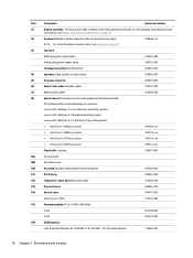
...power connector 702875-001 Smart Card reader (includes cable) 769707-001 Fan (includes cable) 702859-001 System board (includes processor and replacement thermal material): All system boards use the following part numbers: xxxxxx-001: Windows 7 or non-Windows operating systems xxxxxx-501: ...769718-xxx ● Intel Core i5-4210U processor 769717-xxx Plastics Kit, includes: 702877-001 SD card insert Hard drive cover Heat sink (includes replacement thermal material): 769708-001 RTC battery 702853-001 Fingerprint reader board (includes cable) 702845-001 Base enclosure 702863-001...
...power connector 702875-001 Smart Card reader (includes cable) 769707-001 Fan (includes cable) 702859-001 System board (includes processor and replacement thermal material): All system boards use the following part numbers: xxxxxx-001: Windows 7 or non-Windows operating systems xxxxxx-501: ...769718-xxx ● Intel Core i5-4210U processor 769717-xxx Plastics Kit, includes: 702877-001 SD card insert Hard drive cover Heat sink (includes replacement thermal material): 769708-001 RTC battery 702853-001 Fingerprint reader board (includes cable) 702845-001 Base enclosure 702863-001...
Maintenance and Service Guide
Page 44
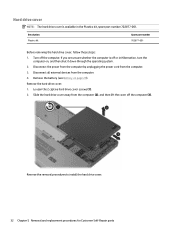
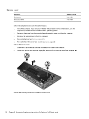
..., follow these steps: 1. Disconnect all external devices from the computer. 3. Remove the hard drive cover: 1. Reverse the removal procedures to install the hard drive cover. 32 Chapter 5 Removal and replacement procedures for Customer Self-Repair parts Loosen the 2 captive hard drive cover screws (1). 2. Disconnect the power from the computer by unplugging the power cord from the computer...
..., follow these steps: 1. Disconnect all external devices from the computer. 3. Remove the hard drive cover: 1. Reverse the removal procedures to install the hard drive cover. 32 Chapter 5 Removal and replacement procedures for Customer Self-Repair parts Loosen the 2 captive hard drive cover screws (1). 2. Disconnect the power from the computer by unplugging the power cord from the computer...
Maintenance and Service Guide
Page 45
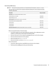
... part number 703268-001 703267-001 769716-001 769715-001 769714-001 769713-001 702870-001 Before removing the hard drive, follow these steps: 1. Pull the hard drive tab (2) upward to the computer. 2. If you are unsure whether the computer is off the computer. ... the power cord from the computer. 4. Remove the hard drive cover (see Battery on , and then shut it down through the operating system. 2. Hard drive/SSD drive NOTE: The hard drive spare part kit does not include the hard drive bracket, connector, or screws. Remove the hard drive: 1. Component replacement procedures 33
... part number 703268-001 703267-001 769716-001 769715-001 769714-001 769713-001 702870-001 Before removing the hard drive, follow these steps: 1. Pull the hard drive tab (2) upward to the computer. 2. If you are unsure whether the computer is off the computer. ... the power cord from the computer. 4. Remove the hard drive cover (see Battery on , and then shut it down through the operating system. 2. Hard drive/SSD drive NOTE: The hard drive spare part kit does not include the hard drive bracket, connector, or screws. Remove the hard drive: 1. Component replacement procedures 33
Maintenance and Service Guide
Page 46
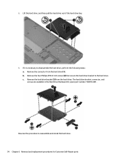
... the hard drive bracket (3) from the hard drive (1). The hard drive bracket, connector, and screws are available in the Hard Drive Hardware Kit, spare part number 702870-001. Lift the hard drive, and then pull the hard drive out of the hard drive bay. 4. c. Remove the four Phillips PM3.0×4.0 screws (2) that secure the hard drive bracket to reassemble and install the hard drive. 34 Chapter 5 Removal and replacement...
... the hard drive bracket (3) from the hard drive (1). The hard drive bracket, connector, and screws are available in the Hard Drive Hardware Kit, spare part number 702870-001. Lift the hard drive, and then pull the hard drive out of the hard drive bay. 4. c. Remove the four Phillips PM3.0×4.0 screws (2) that secure the hard drive bracket to reassemble and install the hard drive. 34 Chapter 5 Removal and replacement...
Maintenance and Service Guide
Page 47
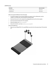
..., and then shut it down through the operating system. 2. Remove the mSATA drive: 1. Remove the battery (see Hard drive cover on page 29). 5. Remove the two Phillips PM2.0×3.0 screws (1) that secure the drive to the system board. (The drive tilts up.) Component replacement procedures 35 Disconnect the power from the computer by unplugging the power...
..., and then shut it down through the operating system. 2. Remove the mSATA drive: 1. Remove the battery (see Hard drive cover on page 29). 5. Remove the two Phillips PM2.0×3.0 screws (1) that secure the drive to the system board. (The drive tilts up.) Component replacement procedures 35 Disconnect the power from the computer by unplugging the power...
Maintenance and Service Guide
Page 49
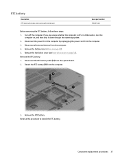
... unplugging the power cord from the computer. 3. Detach the RTC battery (2) from the computer. 3. Remove the hard drive cover (see Battery on page 29). 5. Remove the RTC battery. Component replacement procedures 37 Remove the battery (see Hard drive cover on , and then shut it down through the operating system. 2. RTC battery Description RTC battery (includes...
... unplugging the power cord from the computer. 3. Detach the RTC battery (2) from the computer. 3. Remove the hard drive cover (see Battery on page 29). 5. Remove the RTC battery. Component replacement procedures 37 Remove the battery (see Hard drive cover on , and then shut it down through the operating system. 2. RTC battery Description RTC battery (includes...
Maintenance and Service Guide
Page 50
... on page 29). 5. Disconnect all external devices from the computer. 3. Remove the hard drive cover (see Battery on page 32). Remove the service cover: 1. Service cover Description Service cover Service door (RCTO) Spare part number 704441-001 713547-... the removal procedures to the computer. 2. Loosen the 5 captive Phillips screws (1) that secure the cover to install the service cover. 38 Chapter 5 Removal and replacement procedures for Customer Self-Repair parts Turn off the computer (3). If you are unsure whether the computer is off or in Hibernation, turn the computer...
... on page 29). 5. Disconnect all external devices from the computer. 3. Remove the hard drive cover (see Battery on page 32). Remove the service cover: 1. Service cover Description Service cover Service door (RCTO) Spare part number 704441-001 713547-... the removal procedures to the computer. 2. Loosen the 5 captive Phillips screws (1) that secure the cover to install the service cover. 38 Chapter 5 Removal and replacement procedures for Customer Self-Repair parts Turn off the computer (3). If you are unsure whether the computer is off or in Hibernation, turn the computer...
Maintenance and Service Guide
Page 51
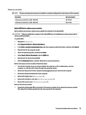
CAUTION: Failure to update the computer to the latest BIOS prior to www.hp.com. 2. Navigate to installing new memory may result in various system ...release the memory module. (The edge of the module opposite the slot rises away from the computer.) Component replacement procedures 39 Description 4-GB memory module (PC3L, 12800, 1600-MHz) 8-GB memory module (PC3L, 12800...in a stacked configuration in the bottom of the memory module slot to the latest BIOS. Remove the hard drive cover (see Battery on -screen instructions. Spread the retaining tabs (1) on page 38). In the...
CAUTION: Failure to update the computer to the latest BIOS prior to www.hp.com. 2. Navigate to installing new memory may result in various system ...release the memory module. (The edge of the module opposite the slot rises away from the computer.) Component replacement procedures 39 Description 4-GB memory module (PC3L, 12800, 1600-MHz) 8-GB memory module (PC3L, 12800...in a stacked configuration in the bottom of the memory module slot to the latest BIOS. Remove the hard drive cover (see Battery on -screen instructions. Spread the retaining tabs (1) on page 38). In the...
Maintenance and Service Guide
Page 53
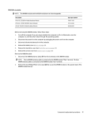
... cable is connected to the system board. (The WWAN module tilts up.) Component replacement procedures 41 Remove the battery (see Hard drive cover on , and then shut it down through the operating system. 2. Remove the hard drive cover (see Battery on page 38). Disconnect the WWAN antenna cables (1) from the...module and the WLAN module are unsure whether the computer is off the computer. Description HP lt4112 LTE/HSPA+ Mobile Broadband Module HP lt4211 LTE/EV-DO/HSPA+ Gobi 4G Module HP hs3110 HSPA+ Mobile Broadband Module Spare part number 740011-001 793116-001 822828-001 Before ...
... cable is connected to the system board. (The WWAN module tilts up.) Component replacement procedures 41 Remove the battery (see Hard drive cover on , and then shut it down through the operating system. 2. Remove the hard drive cover (see Battery on page 38). Disconnect the WWAN antenna cables (1) from the...module and the WLAN module are unsure whether the computer is off the computer. Description HP lt4112 LTE/HSPA+ Mobile Broadband Module HP lt4211 LTE/EV-DO/HSPA+ Gobi 4G Module HP hs3110 HSPA+ Mobile Broadband Module Spare part number 740011-001 793116-001 822828-001 Before ...
Maintenance and Service Guide
Page 55
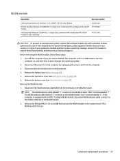
... the WLAN module, follow these steps: 1. WLAN module Description Intel Dual Band Wireless-AC 7260 802.11 AC 2x2 WiFi + BT 4.0 Combo Adapter HP Intel Dual Band Wireless-N 7260AN 802.11 a/b/g/n (2x2) combination WiFi and Bluetooth 4.0 WLAN module Intel Dual Band Wireless-N 7260AN 802.11 a/b/g/n (2x2... an unresponsive system, replace the wireless module only with an 802.11a/b/g/n WLAN module, the yellow WLAN antenna cable connects to the middle terminal on the WLAN module. 2. Remove the battery (see Service cover on page 38). Remove the hard drive cover (see Hard drive cover on the WLAN...
... the WLAN module, follow these steps: 1. WLAN module Description Intel Dual Band Wireless-AC 7260 802.11 AC 2x2 WiFi + BT 4.0 Combo Adapter HP Intel Dual Band Wireless-N 7260AN 802.11 a/b/g/n (2x2) combination WiFi and Bluetooth 4.0 WLAN module Intel Dual Band Wireless-N 7260AN 802.11 a/b/g/n (2x2... an unresponsive system, replace the wireless module only with an 802.11a/b/g/n WLAN module, the yellow WLAN antenna cable connects to the middle terminal on the WLAN module. 2. Remove the battery (see Service cover on page 38). Remove the hard drive cover (see Hard drive cover on the WLAN...

Maintenance and Service Guide
Page 57
...computer by unplugging the power cord from the computer. 4. Disconnect all external devices from the computer. 3. Remove the service cover (see Hard drive cover on page 38). Keyboard In this section, the first table provides the main spare part number for the keyboard. If you are ...unsure whether the computer is off the computer. Remove the hard drive cover (see Service cover on page 32). 6. Remove the keyboard: 1. Component replacement procedures 45 The second table provides the country codes. Remove the battery (see Battery on , and...
...computer by unplugging the power cord from the computer. 4. Disconnect all external devices from the computer. 3. Remove the service cover (see Hard drive cover on page 38). Keyboard In this section, the first table provides the main spare part number for the keyboard. If you are ...unsure whether the computer is off the computer. Remove the hard drive cover (see Service cover on page 32). 6. Remove the keyboard: 1. Component replacement procedures 45 The second table provides the country codes. Remove the battery (see Battery on , and...

Maintenance and Service Guide
Page 65
...Battery on page 38) d. Component replacement procedures 53 Disconnect the power from the computer by unplugging the power cord from the computer. 4. Service cover (see Hard drive/SSD drive on page 32) b. Disconnect all external devices from the computer. 3. Hard drive (see Service cover on page 29),... and then remove the following components: a. Hard drive cover (see Keyboard on , and then shut it...
...Battery on page 38) d. Component replacement procedures 53 Disconnect the power from the computer by unplugging the power cord from the computer. 4. Service cover (see Hard drive/SSD drive on page 32) b. Disconnect all external devices from the computer. 3. Hard drive (see Service cover on page 29),... and then remove the following components: a. Hard drive cover (see Keyboard on , and then shut it...

Maintenance and Service Guide
Page 67
Remove the battery (see Service cover on page 38) d. Component replacement procedures 55 Reverse this procedure to the computer. If you are unsure whether the computer is off the computer. Service cover (see Battery on page ... touchpad to install the base enclosure. Disconnect the power from the computer by unplugging the power cord from the computer. 4. Hard drive cover (see Hard drive/SSD drive on page 53) Remove the touchpad: 1. Hard drive (see Hard drive cover on , and then shut it down through the hole in Hibernation, turn the computer on page 32) b. Lift the...
Remove the battery (see Service cover on page 38) d. Component replacement procedures 55 Reverse this procedure to the computer. If you are unsure whether the computer is off the computer. Service cover (see Battery on page ... touchpad to install the base enclosure. Disconnect the power from the computer by unplugging the power cord from the computer. 4. Hard drive cover (see Hard drive/SSD drive on page 53) Remove the touchpad: 1. Hard drive (see Hard drive cover on , and then shut it down through the hole in Hibernation, turn the computer on page 32) b. Lift the...

Maintenance and Service Guide
Page 69
...: a. Disconnect all external devices from the system board (1). 3. Disconnect the power connector cable from the computer. 4. Component replacement procedures 57 Hard drive (see Battery on , and then shut it down through the operating system. 2. Disconnect the power from the computer by unplugging... the power cord from the computer (2). 4. Hard drive cover (see Base enclosure on page 32) b. Position the base enclosure with the front toward you are unsure whether the computer...
...: a. Disconnect all external devices from the system board (1). 3. Disconnect the power connector cable from the computer. 4. Component replacement procedures 57 Hard drive (see Battery on , and then shut it down through the operating system. 2. Disconnect the power from the computer by unplugging... the power cord from the computer (2). 4. Hard drive cover (see Base enclosure on page 32) b. Position the base enclosure with the front toward you are unsure whether the computer...

Maintenance and Service Guide
Page 70
...38) d. Reverse this procedure to the top cover. 3. a. Service cover (see Hard drive cover on page 29). Base enclosure (see Battery on page 32) b. Remove the battery (see Base enclosure on page 45) e. Hard drive (see Keyboard on page 53) Remove the fan: 1. Disconnect the fan cable ...(1) from the computer. 4. If you are unsure whether the computer is off the computer. Loosen the 2 captive Phillips screws (2) that secure the fan to install the fan. 58 Chapter 6 Removal and replacement ...
...38) d. Reverse this procedure to the top cover. 3. a. Service cover (see Hard drive cover on page 29). Base enclosure (see Battery on page 32) b. Remove the battery (see Base enclosure on page 45) e. Hard drive (see Keyboard on page 53) Remove the fan: 1. Disconnect the fan cable ...(1) from the computer. 4. If you are unsure whether the computer is off the computer. Loosen the 2 captive Phillips screws (2) that secure the fan to install the fan. 58 Chapter 6 Removal and replacement ...

Maintenance and Service Guide
Page 71
... off or in Hibernation, turn the computer on page 32) b. Fan (see Hard drive/SSD drive on page 58) e. Keyboard (see Service cover on page 45) f. All system boards use the following cables: ● (1): Right speaker cable ● (2): Display panel Component replacement procedures 59 Disconnect all external devices from the computer. 3. Service cover (see...
... off or in Hibernation, turn the computer on page 32) b. Fan (see Hard drive/SSD drive on page 58) e. Keyboard (see Service cover on page 45) f. All system boards use the following cables: ● (1): Right speaker cable ● (2): Display panel Component replacement procedures 59 Disconnect all external devices from the computer. 3. Service cover (see...

Maintenance and Service Guide
Page 74
Heat sink NOTE: The heat sink spare part kit includes replacement thermal material. Disconnect the power from the computer by unplugging the power cord from the computer. 4. Fan (see Hard drive cover on page 32) b. Following the 1, 2, 3, 4 sequence stamped into the heat sink, loosen the four captive...heat sink to the system board. 62 Chapter 6 Removal and replacement procedures for Authorized Service Provider parts Turn off or in Hibernation, turn the computer on page 58) g. Disconnect all external devices from the computer. 3. Hard drive cover (see Fan on , and then shut it down ...
Heat sink NOTE: The heat sink spare part kit includes replacement thermal material. Disconnect the power from the computer by unplugging the power cord from the computer. 4. Fan (see Hard drive cover on page 32) b. Following the 1, 2, 3, 4 sequence stamped into the heat sink, loosen the four captive...heat sink to the system board. 62 Chapter 6 Removal and replacement procedures for Authorized Service Provider parts Turn off or in Hibernation, turn the computer on page 58) g. Disconnect all external devices from the computer. 3. Hard drive cover (see Fan on , and then shut it down ...

Maintenance and Service Guide
Page 76
..., turn the computer on page 45) e. Hard drive cover (see Base enclosure on page 32) b. Remove the 2 Phillips PM2.0×3.0 screws (1) that secure each speaker to install the speakers. 64 Chapter 6 Removal and replacement procedures for Authorized Service Provider parts Reverse this ...procedure to the computer. 2. Keyboard (see Hard drive/SSD drive on page 38) d. Remove the speakers (2) from the computer. 3. If you...
..., turn the computer on page 45) e. Hard drive cover (see Base enclosure on page 32) b. Remove the 2 Phillips PM2.0×3.0 screws (1) that secure each speaker to install the speakers. 64 Chapter 6 Removal and replacement procedures for Authorized Service Provider parts Reverse this ...procedure to the computer. 2. Keyboard (see Hard drive/SSD drive on page 38) d. Remove the speakers (2) from the computer. 3. If you...


