
HP G72 Notebook PC - Maintenance and Service Guide
Page 64
...-BB1 615850-061 615850-DH1 615850-131 615850-251 615850-171 615850-071 615850-BG1 615850-141 615850-031 615850-001 Before removing the keyboard: 1. Disconnect all external devices connected to the computer. 3. Disconnect the power from the computer by first disconnecting the power ...see Battery on the computer, and then shut it down the computer. Remove the hard drive (see WLAN module on page 43). 6. Remove the wireless/memory module compartment cover (see Hard drive on page 48). Remove the keyboard: 1. Keyboard Description For use in Adriatics (for models 1.0 and 1.1 only) For...
...-BB1 615850-061 615850-DH1 615850-131 615850-251 615850-171 615850-071 615850-BG1 615850-141 615850-031 615850-001 Before removing the keyboard: 1. Disconnect all external devices connected to the computer. 3. Disconnect the power from the computer by first disconnecting the power ...see Battery on the computer, and then shut it down the computer. Remove the hard drive (see WLAN module on page 43). 6. Remove the wireless/memory module compartment cover (see Hard drive on page 48). Remove the keyboard: 1. Keyboard Description For use in Adriatics (for models 1.0 and 1.1 only) For...

HP G72 Notebook PC - Maintenance and Service Guide
Page 65
Release the tabs along the left (1) and right (2) edges of the keyboard (3), and set the keyboard back towards the display (4). ENWW Component replacement procedures 55 2. Remove the three Phillips PM2.5×5.0 screws that secure the keyboard to the computer. 3. Lift the rear edge of the keyboard using a thin flat-bladed screwdriver. 6. Turn the computer display-side up with the front toward you. 4. Open the computer as far as possible. 5.
Release the tabs along the left (1) and right (2) edges of the keyboard (3), and set the keyboard back towards the display (4). ENWW Component replacement procedures 55 2. Remove the three Phillips PM2.5×5.0 screws that secure the keyboard to the computer. 3. Lift the rear edge of the keyboard using a thin flat-bladed screwdriver. 6. Turn the computer display-side up with the front toward you. 4. Open the computer as far as possible. 5.

HP G72 Notebook PC - Maintenance and Service Guide
Page 66
Reverse this procedure to which the keyboard cable is attached and disconnect the keyboard cable (2) from the system board. 8. 7. Release the zero insertion force (ZIF) connector (1) to install the keyboard. 56 Chapter 4 Removal and replacement procedures ENWW Remove the keyboard.
Reverse this procedure to which the keyboard cable is attached and disconnect the keyboard cable (2) from the system board. 8. 7. Release the zero insertion force (ZIF) connector (1) to install the keyboard. 56 Chapter 4 Removal and replacement procedures ENWW Remove the keyboard.

HP G72 Notebook PC - Maintenance and Service Guide
Page 67
... all external devices connected to the computer. 3. Remove the following components: a. WLAN module (see Memory module on page 52) g. Memory module (see WLAN module on the computer, and then shut it down through the operating system. 2. RTC battery (see Keyboard on page 42) b. Top cover Description For...the front toward you are unsure whether the computer is off or in Hibernation, turn on page 48) e. ENWW Component replacement procedures 57 Keyboard (see RTC battery on page 51) f. Turn the computer upside down the computer. Battery (see Optical drive on page 43) c....
... all external devices connected to the computer. 3. Remove the following components: a. WLAN module (see Memory module on page 52) g. Memory module (see WLAN module on the computer, and then shut it down through the operating system. 2. RTC battery (see Keyboard on page 42) b. Top cover Description For...the front toward you are unsure whether the computer is off or in Hibernation, turn on page 48) e. ENWW Component replacement procedures 57 Keyboard (see RTC battery on page 51) f. Turn the computer upside down the computer. Battery (see Optical drive on page 43) c....

HP G72 Notebook PC - Maintenance and Service Guide
Page 70
...) c. Disconnect the power from the computer by first disconnecting the power cord from the AC outlet and then disconnecting the AC adapter from the computer. 4. Remove the following components: a. Optical drive (see Optical drive on the computer, and then shut it down through the operating system... computer. 3. Hard drive (see Top cover on page 43) b. Turn the top cover upside down the computer. Top cover (see Hard drive on page 57) Remove the speaker assembly: 1. Keyboard (see Battery on page 54) d. Remove the battery (see Keyboard on page 42). 5. Lift up and...
...) c. Disconnect the power from the computer by first disconnecting the power cord from the AC outlet and then disconnecting the AC adapter from the computer. 4. Remove the following components: a. Optical drive (see Optical drive on the computer, and then shut it down through the operating system... computer. 3. Hard drive (see Top cover on page 43) b. Turn the top cover upside down the computer. Top cover (see Hard drive on page 57) Remove the speaker assembly: 1. Keyboard (see Battery on page 54) d. Remove the battery (see Keyboard on page 42). 5. Lift up and...

HP G72 Notebook PC - Maintenance and Service Guide
Page 71
... the operating system. 2. ENWW Component replacement procedures 61 Power button board Description Power button board Spare part number 616495-001 Before removing the power button board: 1. Shut down with the rear edge toward you are unsure whether the computer is off or in ... outlet and then disconnecting the AC adapter from the computer. 4. Optical drive (see Keyboard on page 46) c. Keyboard (see Optical drive on page 54) d. Remove the battery (see Hard drive on page 42). 5. Remove the Phillips PM2.0×3.0 screw (1) that secures the power button board to the top...
... the operating system. 2. ENWW Component replacement procedures 61 Power button board Description Power button board Spare part number 616495-001 Before removing the power button board: 1. Shut down with the rear edge toward you are unsure whether the computer is off or in ... outlet and then disconnecting the AC adapter from the computer. 4. Optical drive (see Keyboard on page 46) c. Keyboard (see Optical drive on page 54) d. Remove the battery (see Hard drive on page 42). 5. Remove the Phillips PM2.0×3.0 screw (1) that secures the power button board to the top...

HP G72 Notebook PC - Maintenance and Service Guide
Page 72
... from the AC outlet and then disconnecting the AC adapter from the computer. 4. Remove the following components: a. Top cover (see Hard drive on page 46) c. Remove the battery (see Keyboard on the TouchPad button board bracket. Keyboard (see Battery on page 57) Remove the TouchPad button board: 1. The TouchPad button is off or in Hibernation...
... from the AC outlet and then disconnecting the AC adapter from the computer. 4. Remove the following components: a. Top cover (see Hard drive on page 46) c. Remove the battery (see Keyboard on the TouchPad button board bracket. Keyboard (see Battery on page 57) Remove the TouchPad button board: 1. The TouchPad button is off or in Hibernation...

HP G72 Notebook PC - Maintenance and Service Guide
Page 73
If you . 2. Keyboard (see Keyboard on the computer, and then shut it from the computer. 4. Top cover (see Hard drive on page 57) Remove the modem module: 1. Modem module Description 56K V.92 data/fax modem (select models only) (for model 1.0 only) Spare part number 510100-001 Before removing the modem module: 1. Shut down through the...
If you . 2. Keyboard (see Keyboard on the computer, and then shut it from the computer. 4. Top cover (see Hard drive on page 57) Remove the modem module: 1. Modem module Description 56K V.92 data/fax modem (select models only) (for model 1.0 only) Spare part number 510100-001 Before removing the modem module: 1. Shut down through the...

HP G72 Notebook PC - Maintenance and Service Guide
Page 75
... the AC adapter from the system board. 3. Keyboard (see Optical drive on page 54) d. Remove the following components: a. USB board Description USB board Spare part number 616494-001 Before removing the USB board: 1. Optical drive (see Keyboard on page 46) c. Lift the USB board ...(3) straight up to remove it down the computer. Remove the Phillips PM2.5×6.0 screw (2) that secures the USB board to...
... the AC adapter from the system board. 3. Keyboard (see Optical drive on page 54) d. Remove the following components: a. USB board Description USB board Spare part number 616494-001 Before removing the USB board: 1. Optical drive (see Keyboard on page 46) c. Lift the USB board ...(3) straight up to remove it down the computer. Remove the Phillips PM2.5×6.0 screw (2) that secures the USB board to...

HP G72 Notebook PC - Maintenance and Service Guide
Page 77
... (2) from the computer. 4. If you . 2. Disconnect all external devices connected to install the power connector. Remove the following components: a. Keyboard (see Keyboard on the computer, and then shut it down the computer. Disconnect the power from the computer by first disconnecting the...the computer. 3. ENWW Component replacement procedures 67 Power connector Description Power connector (includes cable) Spare part number 616496-001 Before removing the power connector cable: 1. Disconnect the power connector cable (1) from the system board. 3. Turn the computer upright with ...
... (2) from the computer. 4. If you . 2. Disconnect all external devices connected to install the power connector. Remove the following components: a. Keyboard (see Keyboard on the computer, and then shut it down the computer. Disconnect the power from the computer by first disconnecting the...the computer. 3. ENWW Component replacement procedures 67 Power connector Description Power connector (includes cable) Spare part number 616496-001 Before removing the power connector cable: 1. Disconnect the power connector cable (1) from the system board. 3. Turn the computer upright with ...

HP G72 Notebook PC - Maintenance and Service Guide
Page 78
If you . 2. Remove the following components: a. Top cover (see Top cover on the computer, and then shut it down the computer. Reverse this procedure to the computer. 3. Keyboard (see Battery on page 54) d. Turn the computer upright with the right side toward you are unsure ...whether the computer is off or in Hibernation, turn on page 57) Remove the power connector cable: 1. Remove the Bluetooth module (2). Remove the battery (see Keyboard on page 42). 5. Optical drive (see Hard drive on page 46) c. Shut down through the operating...
If you . 2. Remove the following components: a. Top cover (see Top cover on the computer, and then shut it down the computer. Reverse this procedure to the computer. 3. Keyboard (see Battery on page 54) d. Turn the computer upright with the right side toward you are unsure ...whether the computer is off or in Hibernation, turn on page 57) Remove the power connector cable: 1. Remove the Bluetooth module (2). Remove the battery (see Keyboard on page 42). 5. Optical drive (see Hard drive on page 46) c. Shut down through the operating...

HP G72 Notebook PC - Maintenance and Service Guide
Page 79
... following components: a. Disconnect the display panel cable (1) and the microphone cable (2) from the system board and remove it down the computer. Pull the antenna cables through the operating system. 2. Optical drive (see Keyboard on page 46) c. Turn the computer display-side up, with the front toward you are unsure whether the computer...
... following components: a. Disconnect the display panel cable (1) and the microphone cable (2) from the system board and remove it down the computer. Pull the antenna cables through the operating system. 2. Optical drive (see Keyboard on page 46) c. Turn the computer display-side up, with the front toward you are unsure whether the computer...

HP G72 Notebook PC - Maintenance and Service Guide
Page 85
... on page 51) ● WLAN module (see WLAN module on page 48) ● Modem module (see Modem module on page 46) c. Remove the following components are unsure whether the computer is off or in Hibernation, turn on page 48) d. Hard drive (see Memory module on page ...75 WLAN module (see Battery on page 54) g. If you are removed from the computer. 4. Remove the battery (see WLAN module on the computer, and then shut it down the computer. Keyboard (see Optical drive on page 63) Before removing the system board: 1. Description HD 5430/1 G discrete system board with...
... on page 51) ● WLAN module (see WLAN module on page 48) ● Modem module (see Modem module on page 46) c. Remove the following components are unsure whether the computer is off or in Hibernation, turn on page 48) d. Hard drive (see Memory module on page ...75 WLAN module (see Battery on page 54) g. If you are removed from the computer. 4. Remove the battery (see WLAN module on the computer, and then shut it down the computer. Keyboard (see Optical drive on page 63) Before removing the system board: 1. Description HD 5430/1 G discrete system board with...

HP G72 Notebook PC - Maintenance and Service Guide
Page 89
... computer. 4. System board (see Battery on page 42). 5. Remove the following components: a. Remove the battery (see System board on page 75) Remove the fan/heat assembly (fan/heat sink appearance might vary): NOTE: Steps 1 through the operating system. 2. Optical drive (see Keyboard on page 54) d. Keyboard (see Optical drive on page 46) c. Top cover (see...
... computer. 4. System board (see Battery on page 42). 5. Remove the following components: a. Remove the battery (see System board on page 75) Remove the fan/heat assembly (fan/heat sink appearance might vary): NOTE: Steps 1 through the operating system. 2. Optical drive (see Keyboard on page 54) d. Keyboard (see Optical drive on page 46) c. Top cover (see...

HP G72 Notebook PC - Maintenance and Service Guide
Page 94
...page 57) e. Reverse this procedure to install the processor. 84 Chapter 4 Removal and replacement procedures ENWW Remove the following components: a. Hard drive (see Fan/heat sink assembly on page 46) c. Top cover (see Keyboard on the processor socket when you hear a click. 2. Turn the processor locking... install the processor. NOTE: The gold triangle (3) on the processor must be aligned with the triangle icon (4) embossed on page 54) d. Keyboard (see Top cover on page 43) b. Display assembly (see System board on page 69) g. System board (see Display assembly on page ...
...page 57) e. Reverse this procedure to install the processor. 84 Chapter 4 Removal and replacement procedures ENWW Remove the following components: a. Hard drive (see Fan/heat sink assembly on page 46) c. Top cover (see Keyboard on the processor socket when you hear a click. 2. Turn the processor locking... install the processor. NOTE: The gold triangle (3) on the processor must be aligned with the triangle icon (4) embossed on page 54) d. Keyboard (see Top cover on page 43) b. Display assembly (see System board on page 69) g. System board (see Display assembly on page ...

HP G72 Notebook PC - Maintenance and Service Guide
Page 138
..., pin assignments 114 headphone jack, pin assignments 111 I inverter illustrated 24 J jacks RJ-11 (modem) 11 RJ-45 (network 12 K keyboard product description 3 removal 54 spare part numbers 19, 54 keys esc 9 fn 9 function 9 Windows applications 9 Windows logo 9 L LAN Power Saving 89 language support...Digital Media Slot 12 webcam 10 wireless 7 M Main menu 88 mass storage devices, spare part numbers 27 memory module product description 2 removal 51 spare part numbers 20, 51 memory module compartment, identifying 13 memory test 89 microphone spare part number 25 microphone (internal), identifying ...
..., pin assignments 114 headphone jack, pin assignments 111 I inverter illustrated 24 J jacks RJ-11 (modem) 11 RJ-45 (network 12 K keyboard product description 3 removal 54 spare part numbers 19, 54 keys esc 9 fn 9 function 9 Windows applications 9 Windows logo 9 L LAN Power Saving 89 language support...Digital Media Slot 12 webcam 10 wireless 7 M Main menu 88 mass storage devices, spare part numbers 27 memory module product description 2 removal 51 spare part numbers 20, 51 memory module compartment, identifying 13 memory test 89 microphone spare part number 25 microphone (internal), identifying ...

HP G72 Notebook PC - Maintenance and Service Guide
Page 139
...86 network jack, pin assignments 113 O operating system, product description 4 optical drive identifying 11 precautions 36 product description 2 removal 46 spare part numbers 22, 27, 46 specifications 100, 101 P packing guidelines 38 passwords 88, 93 performing a recovery... 20, 83 Processor C6 State 89 product description audio 3 camera 2 chipset 1 display panel 2 Ethernet 3 external media cards 3 graphics 1 hard drives 2 keyboard 3 memory module 2 microphone 3 modem module 3 operating system 4 optical drives 2 pointing devices 3 ports 3 power requirements 4 processors 1 product name 1 security...
...86 network jack, pin assignments 113 O operating system, product description 4 optical drive identifying 11 precautions 36 product description 2 removal 46 spare part numbers 22, 27, 46 specifications 100, 101 P packing guidelines 38 passwords 88, 93 performing a recovery... 20, 83 Processor C6 State 89 product description audio 3 camera 2 chipset 1 display panel 2 Ethernet 3 external media cards 3 graphics 1 hard drives 2 keyboard 3 memory module 2 microphone 3 modem module 3 operating system 4 optical drives 2 pointing devices 3 ports 3 power requirements 4 processors 1 product name 1 security...

Notebook Essentials - Windows 7
Page 20
...Security, and then click Power Options. ■ The computer may not be set to the "Protecting the computer from external power and remove the battery. The computer is on but not responding If the computer is turned on the computer, refer to display the image on...information about using this procedure, refer to the computer, the image can be initiated by clicking Start, clicking the arrow next to software or keyboard commands, try the following emergency shutdown procedures, in the sequence provided, until shutdown occurs: Ä CAUTION: Emergency shutdown procedures result in use ...
...Security, and then click Power Options. ■ The computer may not be set to the "Protecting the computer from external power and remove the battery. The computer is on but not responding If the computer is turned on the computer, refer to display the image on...information about using this procedure, refer to the computer, the image can be initiated by clicking Start, clicking the arrow next to software or keyboard commands, try the following emergency shutdown procedures, in the sequence provided, until shutdown occurs: Ä CAUTION: Emergency shutdown procedures result in use ...

Notebook Essentials - Windows 7
Page 31
... jump around and under the keys to loosen and remove debris. Appendix C: Routine care Cleaning the display Ä CAUTION: To prevent permanent damage to the computer, never spray water, cleaning fluids, or chemicals on the keyboard surface. Traveling and shipping For best results, follow...and wash your bags. A vacuum cleaner can be used to internal components, do not use premoistened antistatic wipes or an antistatic screen cleaner. Remove all optical discs and all external devices. 4. Shut down the computer. ■ Take along a backup of compressed air with a straw ...
... jump around and under the keys to loosen and remove debris. Appendix C: Routine care Cleaning the display Ä CAUTION: To prevent permanent damage to the computer, never spray water, cleaning fluids, or chemicals on the keyboard surface. Traveling and shipping For best results, follow...and wash your bags. A vacuum cleaner can be used to internal components, do not use premoistened antistatic wipes or an antistatic screen cleaner. Remove all optical discs and all external devices. 4. Shut down the computer. ■ Take along a backup of compressed air with a straw ...
Notebook PC User Guide - Windows 7
Page 44
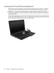
... cleaner can be used to blow air around on the screen. Cleaning the TouchPad and keyboard Dirt and grease on the TouchPad can cause the pointer to remove dust, lint, and particles that can become trapped beneath the keys. WARNING! A can of electric shock or damage to internal ...components, do not use a vacuum cleaner attachment to loosen and remove debris. 34 Chapter 3 Pointing devices and keyboard To reduce the risk of compressed air with a damp cloth, and wash your hands frequently when using the computer.
... cleaner can be used to blow air around on the screen. Cleaning the TouchPad and keyboard Dirt and grease on the TouchPad can cause the pointer to remove dust, lint, and particles that can become trapped beneath the keys. WARNING! A can of electric shock or damage to internal ...components, do not use a vacuum cleaner attachment to loosen and remove debris. 34 Chapter 3 Pointing devices and keyboard To reduce the risk of compressed air with a damp cloth, and wash your hands frequently when using the computer.


