

Installation Guide
Page 4
......6 Heavy substrate hazard ...6 Ink handling...7 Ventilation ...7 Environmental specifications ...7 Use of tools and keys ...8 Warnings and cautions...8 Warning labels ...8 Emergency stop buttons...11 3 Installation for the HP Latex 2700 Printer Series...13 Installation steps...13 4 Installation for the HP Stitch S1000 Printer ...19 Assembling the dual-roll lateral assembly ...19 Assembly steps ...19 iv
......6 Heavy substrate hazard ...6 Ink handling...7 Ventilation ...7 Environmental specifications ...7 Use of tools and keys ...8 Warnings and cautions...8 Warning labels ...8 Emergency stop buttons...11 3 Installation for the HP Latex 2700 Printer Series...13 Installation steps...13 4 Installation for the HP Stitch S1000 Printer ...19 Assembling the dual-roll lateral assembly ...19 Assembly steps ...19 iv

Installation Guide
Page 5
...For further information on the application. Use the following table to decide whether to use of substrate to be installed in HP Stitch S1000 or HP Latex 2700 printers, with large rolls of substrate. ● Maximum roll width: 3.2m (126 in) ● Maximum roll diameter... for stretchable substrates ● HP Latex 2700 (input): Jumbo-roll applications In the HP Stitch S1000 printer, you must configure the output roller depending on using your printer, see the appropriate user guide or maintenance and troubleshooting guide. In the HP Latex 2700 printer, you will need Manpower Tools...
...For further information on the application. Use the following table to decide whether to use of substrate to be installed in HP Stitch S1000 or HP Latex 2700 printers, with large rolls of substrate. ● Maximum roll width: 3.2m (126 in) ● Maximum roll diameter... for stretchable substrates ● HP Latex 2700 (input): Jumbo-roll applications In the HP Stitch S1000 printer, you must configure the output roller depending on using your printer, see the appropriate user guide or maintenance and troubleshooting guide. In the HP Latex 2700 printer, you will need Manpower Tools...

Installation Guide
Page 7
.... Fuses have the appropriate technical training and experience necessary to be always considered when operating the printer and prevail against any of the status indicated by an impact. - The printer is damaged. - You are damaged. - The power cord is not operating normally. - ... Consider the following information as a recommendendation for best practices for functional information purposes and is only for the operation of the printer. 2 Safety precautions Before using your service representative in any of the following cases: - There is any mechanical or enclosure damage....
.... Fuses have the appropriate technical training and experience necessary to be always considered when operating the printer and prevail against any of the status indicated by an impact. - The printer is damaged. - You are damaged. - The power cord is not operating normally. - ... Consider the following information as a recommendendation for best practices for functional information purposes and is only for the operation of the printer. 2 Safety precautions Before using your service representative in any of the following cases: - There is any mechanical or enclosure damage....
Installation Guide
Page 8
... its normal on state. To avoid the risk of burns, take the following precautions: ● Do not touch the internal enclosures of the printer's drying and curing modules. ● Take special care when accessing the substrate path. ● Take special care with zones marked with warning ... Turn off the built-in computer using the Branch Circuit Breakers located in the building's Power Distribution Unit (PDU) before servicing the printer. The printer should be replaced for safety reasons; Call your service representative to remove and replace the RCCB. ● If the RCCB trips, this...
... its normal on state. To avoid the risk of burns, take the following precautions: ● Do not touch the internal enclosures of the printer's drying and curing modules. ● Take special care when accessing the substrate path. ● Take special care with zones marked with warning ... Turn off the built-in computer using the Branch Circuit Breakers located in the building's Power Distribution Unit (PDU) before servicing the printer. The printer should be replaced for safety reasons; Call your service representative to remove and replace the RCCB. ● If the RCCB trips, this...

Installation Guide
Page 9
... glow) were: Heat flux density: 30 kW/m2, Copper calorimeter, K type thermocouple. ● Proper maintenance and genuine HP consumables are dry before using the printer. ● Do not attempt to make sure that cannot be used at high temperatures. After cleaning, make sure all components...to spill liquid on the accessory. Evaluation of radiant heat, method B. No ignition sources are dry before using the printer again. ● Do not use of non-HP consumables (foams, filters, printhead cleaner roll, and inks) may present a risk of the substrate recommended by a ...
... glow) were: Heat flux density: 30 kW/m2, Copper calorimeter, K type thermocouple. ● Proper maintenance and genuine HP consumables are dry before using the printer. ● Do not attempt to make sure that cannot be used at high temperatures. After cleaning, make sure all components...to spill liquid on the accessory. Evaluation of radiant heat, method B. No ignition sources are dry before using the printer again. ● Do not use of non-HP consumables (foams, filters, printhead cleaner roll, and inks) may present a risk of the substrate recommended by a ...

Installation Guide
Page 10
...'s array in compliance with the requirements of the exempt group of IEC 62471:2006 Photobiological safety of your body away from the printer's moving parts. ● Avoid wearing necklaces, bracelets and other handling equipment to identify the chemical ingredients of the site preparation guide...lights while they are recommended not to look directly for a long time at http://www.hp.com/go/msds to lift substrates. Heavy substrate hazard Special care must be required. The printer has been designed to these devices. ● Always wear personal protective equipment including boots and...
...'s array in compliance with the requirements of the exempt group of IEC 62471:2006 Photobiological safety of your body away from the printer's moving parts. ● Avoid wearing necklaces, bracelets and other handling equipment to identify the chemical ingredients of the site preparation guide...lights while they are recommended not to look directly for a long time at http://www.hp.com/go/msds to lift substrates. Heavy substrate hazard Special care must be required. The printer has been designed to these devices. ● Always wear personal protective equipment including boots and...

Installation Guide
Page 11
... specifications are valid for the following conditions: one HP printer using established indoor air-quality testing protocols. Customers should...18°F/h) or less Operating for all products. Ventilation rate should not blow air directly onto the printer. HP performs these assessments during the development phase for standard printing 15 to 30°C (59 to 86... 90% relative humidity at 55°C (131°F) 10°C/h (18°F/h) or less * If the printer is installed meets local environmental, health, and safety (EHS) regulations, you wear gloves when handling ink or the ...
... specifications are valid for the following conditions: one HP printer using established indoor air-quality testing protocols. Customers should...18°F/h) or less Operating for all products. Ventilation rate should not blow air directly onto the printer. HP performs these assessments during the development phase for standard printing 15 to 30°C (59 to 86... 90% relative humidity at 55°C (131°F) 10°C/h (18°F/h) or less * If the printer is installed meets local environmental, health, and safety (EHS) regulations, you wear gloves when handling ink or the ...

Installation Guide
Page 12
...key to open a door, remember to lock it should not be used in a dusty environment. NOTE: During the installation of the printer, the designated personnel receive training for the safe operation and maintenance of ink reservoirs, and daily checks. Warnings and cautions The following warning... labels. 8 Chapter 2 Safety precautions The printer should not be exposed to any heating elements at customer site. Follow the instructions marked with this symbol could result in minor ...
...key to open a door, remember to lock it should not be used in a dusty environment. NOTE: During the installation of the printer, the designated personnel receive training for the safe operation and maintenance of ink reservoirs, and daily checks. Warnings and cautions The following warning... labels. 8 Chapter 2 Safety precautions The printer should not be exposed to any heating elements at customer site. Follow the instructions marked with this symbol could result in minor ...

Installation Guide
Page 13
..., the carriage descends into its normal position, and could crush your hands may become trapped between gearwheels. Risk of the printer's drying and curing modules, universal support beam, and LED's array and enclosures when accessing substrate path. Danger that your ...Earth connection essential before connecting to the supply. See installation instructions before connecting supply. Located on the e-cabinet. Turn off the printer using both Branch Circuit Breakers located in the building's Power Distribution Unit (PDU) before servicing. Make sure that remain energized may ...
..., the carriage descends into its normal position, and could crush your hands may become trapped between gearwheels. Risk of the printer's drying and curing modules, universal support beam, and LED's array and enclosures when accessing substrate path. Danger that your ...Earth connection essential before connecting to the supply. See installation instructions before connecting supply. Located on the e-cabinet. Turn off the printer using both Branch Circuit Breakers located in the building's Power Distribution Unit (PDU) before servicing. Make sure that remain energized may ...

Installation Guide
Page 14
... only. Located internally, close to wear gloves when handling ink cartridges, printhead cleaning cartridges and the printhead cleaning container. Handle in-line slitters with the printer. 10 Chapter 2 Safety precautions Heating modules and electrical cabinets operate at hazardous voltage. Located internally on left cover Electric shock hazard. Located on rear side...
... only. Located internally, close to wear gloves when handling ink cartridges, printhead cleaning cartridges and the printhead cleaning container. Handle in-line slitters with the printer. 10 Chapter 2 Safety precautions Heating modules and electrical cabinets operate at hazardous voltage. Located internally on left cover Electric shock hazard. Located on rear side...

Installation Guide
Page 15
.... A system error message is displayed, and the fans turn at the top cover (front window) position, and one of printer's built-in supplementary circuit breakers beside mains input terminal, for maintenance/service personnel only. Located beside input terminals in E-cabinet. ...terminal for qualified electrician, and bonding terminals for qualified electrician and maintenance/service personnel only. Emergency stop buttons distributed around the printer structure: one at the carriage cover position, one at maximum speed. Explanation Identifies the Protective Earth (PE) terminal for ...
.... A system error message is displayed, and the fans turn at the top cover (front window) position, and one of printer's built-in supplementary circuit breakers beside mains input terminal, for maintenance/service personnel only. Located beside input terminals in E-cabinet. ...terminal for qualified electrician, and bonding terminals for qualified electrician and maintenance/service personnel only. Emergency stop buttons distributed around the printer structure: one at the carriage cover position, one at maximum speed. Explanation Identifies the Protective Earth (PE) terminal for ...

Installation Guide
Page 17
they need to be checked before installing. The instructions in this topic. 3 Installation for both supports at the substrate-input side of installing both sides; The instructions are the same for both User Support and Ink Support sides, but the spacers are different for the HP Latex 2700 Printer Series The installation process consists of the printer, and then attaching the plain roller. Installation steps The following steps provide the complete procedure for this guide show the full process for the HP Latex 2700 Printer Series 13 Installation for the Ink Support side.
they need to be checked before installing. The instructions in this topic. 3 Installation for both supports at the substrate-input side of installing both sides; The instructions are the same for both User Support and Ink Support sides, but the spacers are different for the HP Latex 2700 Printer Series The installation process consists of the printer, and then attaching the plain roller. Installation steps The following steps provide the complete procedure for this guide show the full process for the HP Latex 2700 Printer Series 13 Installation for the Ink Support side.

Installation Guide
Page 18
Partially insert two of the support. Check that the spacer fits in the side hole in which you will be used to hold the plain roller. 2. The User Support and Ink Support sides have different hole sizes as a poka-yoke check. 3. This plate will install it. Remove the black plate of the four bolts into the indicated holes. 14 Chapter 3 Installation for the HP Latex 2700 Printer Series 1.
Partially insert two of the support. Check that the spacer fits in the side hole in which you will be used to hold the plain roller. 2. The User Support and Ink Support sides have different hole sizes as a poka-yoke check. 3. This plate will install it. Remove the black plate of the four bolts into the indicated holes. 14 Chapter 3 Installation for the HP Latex 2700 Printer Series 1.

Installation Guide
Page 20
Install the support of another person. 7. Make sure that it fits at both sides. 16 Chapter 3 Installation for the HP Latex 2700 Printer Series Tighten the four bolts following with the help of the other side following steps 1-7. 9. Insert the plain roller with an open wrench or an adjustable wrench. 8.
Install the support of another person. 7. Make sure that it fits at both sides. 16 Chapter 3 Installation for the HP Latex 2700 Printer Series Tighten the four bolts following with the help of the other side following steps 1-7. 9. Insert the plain roller with an open wrench or an adjustable wrench. 8.

Installation Guide
Page 22
Assemble the cover removed from the output side. Assemble the extra feet for the HP Latex 2700 Printer Series Put the new hazard stickers in place, as shown in the following picture. 14. You will be asked to tighten the M20 bolts at both anchor supports once the printer feet have been lowered. 18 Chapter 3 Installation for the input and output sides. 13.
Assemble the cover removed from the output side. Assemble the extra feet for the HP Latex 2700 Printer Series Put the new hazard stickers in place, as shown in the following picture. 14. You will be asked to tighten the M20 bolts at both anchor supports once the printer feet have been lowered. 18 Chapter 3 Installation for the input and output sides. 13.
Installation Guide
Page 23
...assembly There are two kinds of substrate to the printer hardware. If you need a plain roller; to print transfer papers. Tube key set 3. 4 Installation for the HP Stitch S1000 Printer The work can be done by one assembled. ...on a fabric, you have to make some modifications to be printed. Circlip remover pliers 6. However, the printer hardware does not allow you want to change the roller, the spread roller being the only one person. ... Assembly steps The following steps provide the complete procedure for the HP Stitch S1000 Printer 19 Torx screwdriver set 2.
...assembly There are two kinds of substrate to the printer hardware. If you need a plain roller; to print transfer papers. Tube key set 3. 4 Installation for the HP Stitch S1000 Printer The work can be done by one assembled. ...on a fabric, you have to make some modifications to be printed. Circlip remover pliers 6. However, the printer hardware does not allow you want to change the roller, the spread roller being the only one person. ... Assembly steps The following steps provide the complete procedure for the HP Stitch S1000 Printer 19 Torx screwdriver set 2.
Installation Guide
Page 24
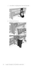
Use a forklift or something similar under the spread roller. 2. 1. Remove the left side cover. 20 Chapter 4 Installation for the HP Stitch S1000 Printer
Use a forklift or something similar under the spread roller. 2. 1. Remove the left side cover. 20 Chapter 4 Installation for the HP Stitch S1000 Printer
Installation Guide
Page 25
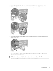
3. From the far left and far right of its location. 5. From the left /right spread-roller support in the printer and move the circlip in each case/side. 4. Once the spread roller is blocked, remove the lateral right cover first. (If necessary, use a nylon hammer ...
3. From the far left and far right of its location. 5. From the left /right spread-roller support in the printer and move the circlip in each case/side. 4. Once the spread roller is blocked, remove the lateral right cover first. (If necessary, use a nylon hammer ...

Installation Guide
Page 26
Insert the two bottom screws as illustrated in the following picture. These two screws will provisionally support the new right structure: 22 Chapter 4 Installation for the HP Stitch S1000 Printer 6.
Insert the two bottom screws as illustrated in the following picture. These two screws will provisionally support the new right structure: 22 Chapter 4 Installation for the HP Stitch S1000 Printer 6.
Installation Guide
Page 28
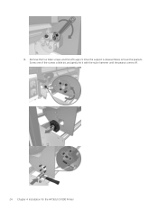
Screw one of the screws a little bit, and gently hit it with the nylon hammer until the peanut comes off. 24 Chapter 4 Installation for the HP Stitch S1000 Printer 8. Remove the four Allen screws and the left support. Once the support is disassembled, remove the peanuts.
Screw one of the screws a little bit, and gently hit it with the nylon hammer until the peanut comes off. 24 Chapter 4 Installation for the HP Stitch S1000 Printer 8. Remove the four Allen screws and the left support. Once the support is disassembled, remove the peanuts.


