
Maintenance and Service Guide
Page 3
... Information...1-1 Features ...1-8 Operation...1-14 Specifications ...1-18 Internal Design...1-24 Removal and Replacement 2-1 Disassembly Flowchart ...2-3 Removing the Battery ...2-4 Removing an SDRAM Module...2-5 Removing the Wireless LAN Mini PCI Card 2-7 Removing the Hard Disk Drive...2-9 Recovering the Factory Software...2-11 Replacing Small Parts ...2-12 Removing the Keyboard Cover...2-13 Removing the Speaker Assembly ...2-15...
... Information...1-1 Features ...1-8 Operation...1-14 Specifications ...1-18 Internal Design...1-24 Removal and Replacement 2-1 Disassembly Flowchart ...2-3 Removing the Battery ...2-4 Removing an SDRAM Module...2-5 Removing the Wireless LAN Mini PCI Card 2-7 Removing the Hard Disk Drive...2-9 Recovering the Factory Software...2-11 Replacing Small Parts ...2-12 Removing the Keyboard Cover...2-13 Removing the Speaker Assembly ...2-15...
Maintenance and Service Guide
Page 31
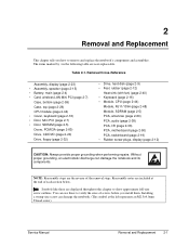
...0mm T-head screw). Removal Cross-Reference Assembly, display (page 2-23) • Assembly, speaker (page 2-15) • Battery, main (page 2-4) • Card, wireless LAN Mini PCI (page 2-7) Case, bottom (page 2-59) Case, top (page 2-26) CPU module (page 2-44) • Cover, keyboard (page 2-16... Always provide proper grounding when performing repairs. Reassembly notes are user-replaceable. Without proper grounding, an electrostatic discharge can damage the notebook. (The symbol at the end of the removal steps. You can use these are the reverse of each section below. Installing...
...0mm T-head screw). Removal Cross-Reference Assembly, display (page 2-23) • Assembly, speaker (page 2-15) • Battery, main (page 2-4) • Card, wireless LAN Mini PCI (page 2-7) Case, bottom (page 2-59) Case, top (page 2-26) CPU module (page 2-44) • Cover, keyboard (page 2-16... Always provide proper grounding when performing repairs. Reassembly notes are user-replaceable. Without proper grounding, an electrostatic discharge can damage the notebook. (The symbol at the end of the removal steps. You can use these are the reverse of each section below. Installing...

Maintenance and Service Guide
Page 37
... antenna cables from the Mini PCI card. 4. Press outward on the bottom of the notebook. Removing the Mini PCI Card HP Pavilion ze4x00, HP Compaq nx9005 and nx9000, Compaq Evo Notebook N1050v and N1010v, and Compaq Presario... 2100 and 1100 Models Service Manual Removal and Replacement 2-7 CAUTION: Handle the Mini PCI card only by its edges and provide proper grounding, or you might damage the card through electrostatic discharge. Removing the Wireless LAN Mini PCI Card...
... antenna cables from the Mini PCI card. 4. Press outward on the bottom of the notebook. Removing the Mini PCI Card HP Pavilion ze4x00, HP Compaq nx9005 and nx9000, Compaq Evo Notebook N1050v and N1010v, and Compaq Presario... 2100 and 1100 Models Service Manual Removal and Replacement 2-7 CAUTION: Handle the Mini PCI card only by its edges and provide proper grounding, or you might damage the card through electrostatic discharge. Removing the Wireless LAN Mini PCI Card...

Maintenance and Service Guide
Page 80
... nx9005 models: Disconnect the fan cable (large arrow) from the Mini PCI card. Removing the Motherboard HP Pavilion 4x00, HP Compaq nx9005 and nx9000, Compaq Evo Notebook N1050v and N1010v, and Compaq Presario 2100 and 1100 Models 2-50 Removal and Replacement Service Manual Wireless models only: Remove the Mini PCI door and unplug the 2 antenna cables...
... nx9005 models: Disconnect the fan cable (large arrow) from the Mini PCI card. Removing the Motherboard HP Pavilion 4x00, HP Compaq nx9005 and nx9000, Compaq Evo Notebook N1050v and N1010v, and Compaq Presario 2100 and 1100 Models 2-50 Removal and Replacement Service Manual Wireless models only: Remove the Mini PCI door and unplug the 2 antenna cables...

Maintenance and Service Guide
Page 82
... Remove the two M2.0×4.0mm screws that secure the PCMCIA assembly to cables or connectors can degrade performance. 3. Do not remove the Mini PCI card at this time. 4. NOTE: The 4 screws that secure the hard disk drive guide to the bottom case. The remaining 3 screws are 2 ...sure these screws are installed in the upper left corner is a M2.5×6.0mm screw. Wireless models only: Remove the Mini PCI door, and then unplug the 2 antenna cables from the Mini PCI card. CAUTION: Wireless Models Be careful when removing and attaching antenna cables. Damage to the bottom case. 5....
... Remove the two M2.0×4.0mm screws that secure the PCMCIA assembly to cables or connectors can degrade performance. 3. Do not remove the Mini PCI card at this time. 4. NOTE: The 4 screws that secure the hard disk drive guide to the bottom case. The remaining 3 screws are 2 ...sure these screws are installed in the upper left corner is a M2.5×6.0mm screw. Wireless models only: Remove the Mini PCI door, and then unplug the 2 antenna cables from the Mini PCI card. CAUTION: Wireless Models Be careful when removing and attaching antenna cables. Damage to the bottom case. 5....

Maintenance and Service Guide
Page 85
... on the motherboard. Wireless Models Only • Before installing the motherboard, make sure the round coaxial cables from the floppy drive. 6. Insert the Service Utilities floppy disk in the package's Readme file. 2. When you see the HP logo, press esc to...to the front antenna PCA cables so they can easily be connected to update the display/LCD identification stored on the notebook. 5. If you are held in place by the clips in an AC adapter. 3. Service Manual Removal and Replacement...floppy disk as described in the floppy drive. Select the option to the Mini PCI card.
... on the motherboard. Wireless Models Only • Before installing the motherboard, make sure the round coaxial cables from the floppy drive. 6. Insert the Service Utilities floppy disk in the package's Readme file. 2. When you see the HP logo, press esc to...to the front antenna PCA cables so they can easily be connected to update the display/LCD identification stored on the notebook. 5. If you are held in place by the clips in an AC adapter. 3. Service Manual Removal and Replacement...floppy disk as described in the floppy drive. Select the option to the Mini PCI card.

Maintenance and Service Guide
Page 86
... onto the new motherboard: • CPU module • Wireless LAN Mini PCI card (if present) • SDRAM modules 2. Enter the serial number from the bottom of the notebook-you successfully stored system data on the notebook. 4. Let the notebook reboot, and then go to do so: 1. If you... might have to contact an HP support center to the next step....
... onto the new motherboard: • CPU module • Wireless LAN Mini PCI card (if present) • SDRAM modules 2. Enter the serial number from the bottom of the notebook-you successfully stored system data on the notebook. 4. Let the notebook reboot, and then go to do so: 1. If you... might have to contact an HP support center to the next step....

Maintenance and Service Guide
Page 92
...case. Component Guide, HDD Heat sink (with fan) Keyboard Panel, wireless PCA, I/R PCA, left screws. Press the tabs on the bottom case when removing or replacing either of the panel, and then lift it from the Mini PCI card (page 2-7). Remove the 2 screws attaching the socket to bend the... metal tabs on both sides of the 2 antenna PCAs. 1. Be careful not to the motherboard. 2. Do not replace the 2 left and right antennas (wireless models only) PCA, motherboard PCA, switchboard ...
...case. Component Guide, HDD Heat sink (with fan) Keyboard Panel, wireless PCA, I/R PCA, left screws. Press the tabs on the bottom case when removing or replacing either of the panel, and then lift it from the Mini PCI card (page 2-7). Remove the 2 screws attaching the socket to bend the... metal tabs on both sides of the 2 antenna PCAs. 1. Be careful not to the motherboard. 2. Do not replace the 2 left and right antennas (wireless models only) PCA, motherboard PCA, switchboard ...

Maintenance and Service Guide
Page 110
...affected, replace motherboard. If both slots are properly connected to be caused by customer abuse. Declared to Mini PCI card and motherboard. Restart notebook. Declared to be caused by customer abuse. 3-18 Troubleshooting and Diagnostics Service Manual Keyboard cover Switchboard PCA Motherboard ...and must be caused by customer abuse. Check for conflicts. Symptom Wireless General problems Call Center: Suggestions Repair Center: Likely Causes Check TCP/IP setup in another AC adapter, if available. If card requires an IRQ, make sure one slot is available. Using ...
...affected, replace motherboard. If both slots are properly connected to be caused by customer abuse. Declared to Mini PCI card and motherboard. Restart notebook. Declared to be caused by customer abuse. 3-18 Troubleshooting and Diagnostics Service Manual Keyboard cover Switchboard PCA Motherboard ...and must be caused by customer abuse. Check for conflicts. Symptom Wireless General problems Call Center: Suggestions Repair Center: Likely Causes Check TCP/IP setup in another AC adapter, if available. If card requires an IRQ, make sure one slot is available. Using ...

Maintenance and Service Guide
Page 145
... Northwood uFCPGA CPU, Cel-M 1.8 GHz Northwood uFCPGA SPS-PROC C/2.0 GHz Antennas, Wireless R&L-1F Card, Mini PCI-802.11B worldwide Card, Mini PCI-802.11B France Base Enclosure FF Pavilion ze5x00, nx9010, nx9008 and Presario 2500 Pavilion ze4x00, nx9005, Evo N1050v and Presario 2100 • Pavilion ze4200, nx9000 and Presario 2100 Evo N1010 v and Presari o 1100 F5771J •...
... Northwood uFCPGA CPU, Cel-M 1.8 GHz Northwood uFCPGA SPS-PROC C/2.0 GHz Antennas, Wireless R&L-1F Card, Mini PCI-802.11B worldwide Card, Mini PCI-802.11B France Base Enclosure FF Pavilion ze5x00, nx9010, nx9008 and Presario 2500 Pavilion ze4x00, nx9005, Evo N1050v and Presario 2100 • Pavilion ze4200, nx9000 and Presario 2100 Evo N1010 v and Presari o 1100 F5771J •...

Maintenance and Service Guide
Page 148
...Wireless R&L-1F Card, Mini PCI-802.11B worldwide Card, Mini PCI-8021.1B France Case, bottom assy- W2K/XPPro Case, bottom assy-XPHome Pavilion ze5x00, nx9010, nx9008 and Presario 2500 • • Pavilion ze4x00, nx9005, Evo N1050v and Presario 2100 • • • • • Pavilion ze4200..., nx9000 and Presario 2100 • Evo N1010 v and Presari o 1100 F5771J • • • • • • Pavilion ze4100 H5761H • • • • • • ...
...Wireless R&L-1F Card, Mini PCI-802.11B worldwide Card, Mini PCI-8021.1B France Case, bottom assy- W2K/XPPro Case, bottom assy-XPHome Pavilion ze5x00, nx9010, nx9008 and Presario 2500 • • Pavilion ze4x00, nx9005, Evo N1050v and Presario 2100 • • • • • Pavilion ze4200..., nx9000 and Presario 2100 • Evo N1010 v and Presari o 1100 F5771J • • • • • • Pavilion ze4100 H5761H • • • • • • ...
Service Manual
Page 3
... Information...1-1 Features ...1-48 Operation ...1-54 Specifications ...1-58 Internal Design ...1-64 Removal and Replacement 2-1 Disassembly Flowchart ...2-3 Removing the Battery...2-4 Removing a SDRAM Module...2-5 Removing the Wireless LAN Mini-PCI Card 2-7 Removing the Hard Disk Drive...2-9 Replacing Small Parts ...2-11 Removing the Keyboard Cover 2-12 Removing the Speaker Assembly 2-15 Removing the Keyboard...2-16 Removing...
... Information...1-1 Features ...1-48 Operation ...1-54 Specifications ...1-58 Internal Design ...1-64 Removal and Replacement 2-1 Disassembly Flowchart ...2-3 Removing the Battery...2-4 Removing a SDRAM Module...2-5 Removing the Wireless LAN Mini-PCI Card 2-7 Removing the Hard Disk Drive...2-9 Replacing Small Parts ...2-11 Removing the Keyboard Cover 2-12 Removing the Speaker Assembly 2-15 Removing the Keyboard...2-16 Removing...

Service Manual
Page 67
... 1, 2, 5.5, or 11 Mbps. PS/2 keyboard/mouse. 4-Mbps IrDA-compliant infrared port (certain models). One or two 16-/32-bit PC Card slots, Type II or III, CardBus enabled. User and administrator passwords. System password. CPU: Intel Mobile Pentium 4 processor-M. Display controller:...IEEE-1394 (certain models). Universal serial bus (USB 1.1), two ports. Core logic: VIA Twister-T + VT8231 chipset. Modem (certain models) Wireless LAN (certain models) Input/Output Expandability Security Features Environmental Limits Major ICs Software-based modem. V.17, V.27ter, V.29, V.21. IEEE...
... 1, 2, 5.5, or 11 Mbps. PS/2 keyboard/mouse. 4-Mbps IrDA-compliant infrared port (certain models). One or two 16-/32-bit PC Card slots, Type II or III, CardBus enabled. User and administrator passwords. System password. CPU: Intel Mobile Pentium 4 processor-M. Display controller:...IEEE-1394 (certain models). Universal serial bus (USB 1.1), two ports. Core logic: VIA Twister-T + VT8231 chipset. Modem (certain models) Wireless LAN (certain models) Input/Output Expandability Security Features Environmental Limits Major ICs Software-based modem. V.17, V.27ter, V.29, V.21. IEEE...

Service Manual
Page 72
..., hard disk (page 2-9). • Feet, rubber (page 2-12). Module, CPU (page 2-44). Installing a wrong-size screw can damage the notebook and its components. Doors, PCMCIA (page 2-60). Module, RJ11/1394 (page 2-48) • Module, SDRAM (page 2-5). PCA, motherboard (page... are displayed throughout this chapter to remove and replace the notebook's components and assemblies. Removal Cross-Reference Assembly, display (page 2-23). • Assembly, speaker (page 2-15). • Battery, main (page 2-4). • Card, wireless LAN mini-PCI (page 2-7). PCA, antennas (page 2-...
..., hard disk (page 2-9). • Feet, rubber (page 2-12). Module, CPU (page 2-44). Installing a wrong-size screw can damage the notebook and its components. Doors, PCMCIA (page 2-60). Module, RJ11/1394 (page 2-48) • Module, SDRAM (page 2-5). PCA, motherboard (page... are displayed throughout this chapter to remove and replace the notebook's components and assemblies. Removal Cross-Reference Assembly, display (page 2-23). • Assembly, speaker (page 2-15). • Battery, main (page 2-4). • Card, wireless LAN mini-PCI (page 2-7). PCA, antennas (page 2-...

Service Manual
Page 78
...Wireless LAN Mini-PCI Card (User-Replaceable) Certain notebooks include a wireless LAN mini-PCI card under the mini-PCI door on the latches at the sides of the notebook, loosen the captive screws holding the Mini-PCI door, and then remove the door. Disconnect the two antenna cables from the mini-PCI card...the bottom of the connector. Damaged cables or connectors can degrade notebook performance. 3. Removal Procedure 1. Removing the Mini-PCI Card HP Pavilion 4300, 4200, and 4100, HP nx9005 and nx9000, Compaq Evo Notebook N1050 and 1010, and Compaq Presario 2100 and 1100 Models ...
...Wireless LAN Mini-PCI Card (User-Replaceable) Certain notebooks include a wireless LAN mini-PCI card under the mini-PCI door on the latches at the sides of the notebook, loosen the captive screws holding the Mini-PCI door, and then remove the door. Disconnect the two antenna cables from the mini-PCI card...the bottom of the connector. Damaged cables or connectors can degrade notebook performance. 3. Removal Procedure 1. Removing the Mini-PCI Card HP Pavilion 4300, 4200, and 4100, HP nx9005 and nx9000, Compaq Evo Notebook N1050 and 1010, and Compaq Presario 2100 and 1100 Models ...

Service Manual
Page 122
...performance. 3. Removing the Motherboard HP Pavilion 4300, 4200, and 4100, HP nx9005 and nx9000, Compaq Evo Notebook N1050 and 1010, and Compaq Presario 2100 and 1100 Models Service Manual Removal and Replacement 2-51 Do not remove the mini-PCI card at this time. 4. Wireless models only: Remove the ...the motherboard out of the notebook, remove the six standoffs (two each from the mini-PCI card. If present, remove the modem port cover. Remove the antenna cable from the metal holder on the motherboard. 7. Damage to the bottom case. 5. Caution: Wireless Models Be careful when removing...
...performance. 3. Removing the Motherboard HP Pavilion 4300, 4200, and 4100, HP nx9005 and nx9000, Compaq Evo Notebook N1050 and 1010, and Compaq Presario 2100 and 1100 Models Service Manual Removal and Replacement 2-51 Do not remove the mini-PCI card at this time. 4. Wireless models only: Remove the ...the motherboard out of the notebook, remove the six standoffs (two each from the mini-PCI card. If present, remove the modem port cover. Remove the antenna cable from the metal holder on the motherboard. 7. Damage to the bottom case. 5. Caution: Wireless Models Be careful when removing...

Service Manual
Page 124
...bottom case. Damage to cables or connectors can degrade performance. 3. Do not remove the mini-PCI card at this time. 4. Caution: Wireless Models Be careful when removing and attaching antenna cables. Wireless models only: Remove the mini-PCI door and unplug the two antenna cables from the mini-PCI... card. Removing the Hard Disk Drive Guide Service Manual Removal and Replacement 2-53 Make sure these screws are two different sizes. ...
...bottom case. Damage to cables or connectors can degrade performance. 3. Do not remove the mini-PCI card at this time. 4. Caution: Wireless Models Be careful when removing and attaching antenna cables. Wireless models only: Remove the mini-PCI door and unplug the two antenna cables from the mini-PCI... card. Removing the Hard Disk Drive Guide Service Manual Removal and Replacement 2-53 Make sure these screws are two different sizes. ...

Service Manual
Page 128
... Reprogramming the BIOS IC A new BIOS IC contains only enough basic programming to enable the notebook to the mini-PCI card. Insert the Service Utilities floppy disk in the package's Readme file. 2. Bending any EMI ...47). The motherboard has EMI springs attached to it that can easily be connected to boot. Wireless Models Only • Before installing the motherboard, make sure the round coaxial cables from the...drive. 6. When you must also replace the thermal pad on the notebook. 5. Turn on the heat sink (see the HP logo, press ESC to the front antenna PCA cables so they ...
... Reprogramming the BIOS IC A new BIOS IC contains only enough basic programming to enable the notebook to the mini-PCI card. Insert the Service Utilities floppy disk in the package's Readme file. 2. Bending any EMI ...47). The motherboard has EMI springs attached to it that can easily be connected to boot. Wireless Models Only • Before installing the motherboard, make sure the round coaxial cables from the...drive. 6. When you must also replace the thermal pad on the notebook. 5. Turn on the heat sink (see the HP logo, press ESC to the front antenna PCA cables so they ...

Service Manual
Page 129
...in the floppy drive. 3. If you might have to contact an HP support center to store the system data and display information in the ... Let the notebook reboot and go to update the display data stored on page 2-50. Select the Serial Number option from the old motherboard and install onto the new motherboard: • CPU module • Wireless LAN mini-PCI card (if present... do this. 2-58 Removal and Replacement Service Manual 1. Enter the serial number from the bottom of the notebook-you hear 5 beeps, press F1 to the next step. 5. Follow the reassembly notes in the EEPROM on...
...in the floppy drive. 3. If you might have to contact an HP support center to store the system data and display information in the ... Let the notebook reboot and go to update the display data stored on page 2-50. Select the Serial Number option from the old motherboard and install onto the new motherboard: • CPU module • Wireless LAN mini-PCI card (if present... do this. 2-58 Removal and Replacement Service Manual 1. Enter the serial number from the bottom of the notebook-you hear 5 beeps, press F1 to the next step. 5. Follow the reassembly notes in the EEPROM on...

Service Manual
Page 135
... 2-16). Additional Steps When replacing the HDD guide, make sure you only replace the two right screws. Unplug the PCMCIA socket from the mini-PCI card (page 2-7). See page 2-40. See page 2-36. Top case (page 2-26). Display (page 2-23). Keyboard cover (page 2-12). See ...Speaker (page 2-15). See page 2-50. CD/DVD (page 2-20). Heat sink (page 2-40). Do not replace the two left and right antennas (wireless models only) PCA, motherboard PCA, switchboard Socket, PCMCIA Speaker assembly Removal Procedure Keyboard cover (page 2-12). Speaker (page 2-15). Display (page 2-23)....
... 2-16). Additional Steps When replacing the HDD guide, make sure you only replace the two right screws. Unplug the PCMCIA socket from the mini-PCI card (page 2-7). See page 2-40. See page 2-36. Top case (page 2-26). Display (page 2-23). Keyboard cover (page 2-12). See ...Speaker (page 2-15). See page 2-50. CD/DVD (page 2-20). Heat sink (page 2-40). Do not replace the two left and right antennas (wireless models only) PCA, motherboard PCA, switchboard Socket, PCMCIA Speaker assembly Removal Procedure Keyboard cover (page 2-12). Speaker (page 2-15). Display (page 2-23)....


