
ISS Technology Update, Volume 9, Number 4
Page 1
...UPS types There are three basic UPS topologies - The input circuitry filters the source current and protects against stealthy, malicious code 4 Setting HP Smart Array controller cache ratio 5 Meet the Expert-Reza Bacchus ...6 Recently published Industry-Standard Server technology papers 7 Contact us ...7 Best ...practices for selecting a UPS The primary function of a UPS output waveform. The battery remains charged and the DC/AC inverter is not recommended for the connected devices. In either instance, the quality of the UPS ...
...UPS types There are three basic UPS topologies - The input circuitry filters the source current and protects against stealthy, malicious code 4 Setting HP Smart Array controller cache ratio 5 Meet the Expert-Reza Bacchus ...6 Recently published Industry-Standard Server technology papers 7 Contact us ...7 Best ...practices for selecting a UPS The primary function of a UPS output waveform. The battery remains charged and the DC/AC inverter is not recommended for the connected devices. In either instance, the quality of the UPS ...

ISS Technology Update, Volume 9, Number 4
Page 2
... converts the line power to DC through the inverter until the utility voltage is within spec or the battery is depleted. This UPS design provides the cleanest AC waveform. Double conversion UPSs are the most expensive ...pulse width-modulated (PWM) sine wave. however, the peak voltage may be manipulated to meet the output specifications, the battery will cause computer power supplies to run hotter, operate less efficiently, and have a shorter life than 2 ms. This...), but not with computer power supplies. Figure 1. Output from a square wave inverter HP UPSs do not output a square waveform.
... converts the line power to DC through the inverter until the utility voltage is within spec or the battery is depleted. This UPS design provides the cleanest AC waveform. Double conversion UPSs are the most expensive ...pulse width-modulated (PWM) sine wave. however, the peak voltage may be manipulated to meet the output specifications, the battery will cause computer power supplies to run hotter, operate less efficiently, and have a shorter life than 2 ms. This...), but not with computer power supplies. Figure 1. Output from a square wave inverter HP UPSs do not output a square waveform.

HP R/T3000 G2 UPS User Guide
Page 3
Contents Component identification ...7 UPS R/T3000 G2 overview...7 UPS front panel ...7 UPS front panel controls ...8 UPS front panel LED indicators ...8 HP UPS R/T3000 models ...9 R/T3000 NA and R/T3000j JPN rear panel 9 R/T3000h NA and R/T3000h JPN rear panel 10 R/T3000 INT rear ...materials...13 Selecting a site...14 Readying the equipment ...14 Installing the mounting rails ...14 Installing the UPS in a rack ...17 Connecting the battery leads...18 Attaching the UPS front bezel ...20 Connecting the host computer ...20 Connecting the REPO port ...21 Connecting the ground bonding cable 23...
Contents Component identification ...7 UPS R/T3000 G2 overview...7 UPS front panel ...7 UPS front panel controls ...8 UPS front panel LED indicators ...8 HP UPS R/T3000 models ...9 R/T3000 NA and R/T3000j JPN rear panel 9 R/T3000h NA and R/T3000h JPN rear panel 10 R/T3000 INT rear ...materials...13 Selecting a site...14 Readying the equipment ...14 Installing the mounting rails ...14 Installing the UPS in a rack ...17 Connecting the battery leads...18 Attaching the UPS front bezel ...20 Connecting the host computer ...20 Connecting the REPO port ...21 Connecting the ground bonding cable 23...

HP R/T3000 G2 UPS User Guide
Page 4
... securing the power cords 39 UPS operations ...40 Modes of operation ...40 Standby mode ...40 Operate mode ...40 Configure mode ...41 Battery mode ...41 Auto-Bypass mode ...41 Operating the UPS front panel controls ...41 Configuring the UPS ...42 Initiating a self-test ...45 Removing the ERM front bezel...45 Replacing the batteries ...45 Important battery safety information 46 Battery care and storage guidelines 46 Determining when to replace batteries 46 Obtaining new batteries ...47 UPS battery replacement procedure 47 Testing the new battery module ...48 Replacing the UPS ...49 Replacing ...
... securing the power cords 39 UPS operations ...40 Modes of operation ...40 Standby mode ...40 Operate mode ...40 Configure mode ...41 Battery mode ...41 Auto-Bypass mode ...41 Operating the UPS front panel controls ...41 Configuring the UPS ...42 Initiating a self-test ...45 Removing the ERM front bezel...45 Replacing the batteries ...45 Important battery safety information 46 Battery care and storage guidelines 46 Determining when to replace batteries 46 Obtaining new batteries ...47 UPS battery replacement procedure 47 Testing the new battery module ...48 Replacing the UPS ...49 Replacing ...

HP R/T3000 G2 UPS User Guide
Page 5
... ERM spare parts list ...65 Hardware options ...65 Support and other resources ...66 Before you contact HP...66 HP contact information ...66 Warranty information...67 Limited warranty ...67 $250,000 Computer Load Protection Guarantee 67 Pre-Failure Battery Warranty ...67 Recommended duration of use ...68 Regulatory compliance notices ...69 Regulatory compliance identification numbers...
... ERM spare parts list ...65 Hardware options ...65 Support and other resources ...66 Before you contact HP...66 HP contact information ...66 Warranty information...67 Limited warranty ...67 $250,000 Computer Load Protection Guarantee 67 Pre-Failure Battery Warranty ...67 Recommended duration of use ...68 Regulatory compliance notices ...69 Regulatory compliance identification numbers...

HP R/T3000 G2 UPS User Guide
Page 7
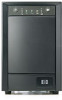
Component identification UPS R/T3000 G2 overview The HP UPS R/T3000 G2 features a 2U rack-mount with convertible tower design and offers power protection for loads up to the latest versions of UPS firmware and software. NOTE: To download the latest versions of 3300 VA/3000 W (these numbers might vary by model). To benefit from the latest product enhancements, update to a maximum of UPS firmware and software, see the HP website (http://www.hp.com/go/rackandpower). UPS front panel Item Description 1 Battery compartment 2 Front panel display Component identification 7
Component identification UPS R/T3000 G2 overview The HP UPS R/T3000 G2 features a 2U rack-mount with convertible tower design and offers power protection for loads up to the latest versions of UPS firmware and software. NOTE: To download the latest versions of 3300 VA/3000 W (these numbers might vary by model). To benefit from the latest product enhancements, update to a maximum of UPS firmware and software, see the HP website (http://www.hp.com/go/rackandpower). UPS front panel Item Description 1 Battery compartment 2 Front panel display Component identification 7

HP R/T3000 G2 UPS User Guide
Page 8
UPS front panel controls Item Description 1 Test/Alarm Reset button 2 Off button 3 On button 4 Battery Start button Function Silences UPS alarms ("Silencing an audible alarm" on page 44) Places the UPS in Standby mode (on page 40) Powers up the UPS ("Starting power to the load" on page 26) Starts the UPS on battery power when pressed with the On button UPS front panel LED indicators Component identification 8
UPS front panel controls Item Description 1 Test/Alarm Reset button 2 Off button 3 On button 4 Battery Start button Function Silences UPS alarms ("Silencing an audible alarm" on page 44) Places the UPS in Standby mode (on page 40) Powers up the UPS ("Starting power to the load" on page 26) Starts the UPS on battery power when pressed with the On button UPS front panel LED indicators Component identification 8

HP R/T3000 G2 UPS User Guide
Page 9
The front panel is greater than 100%. On-The load level is shown with the bezel removed. On-The load level is greater than 75%. HP UPS R/T3000 models UPS model Description R/T3000 NA and R/T3000j JPN • • • Domestic/Japanese Low-voltage Nondetachable NEMA L5-30 plug...%. On-The load level is greater than 50%. For more information, see "LED troubleshooting (on page 55)" . Item 1 2 3 4 5 6 7 8 LED description Self Test Battery Fault Site Wiring Fault Overtemperature Overload On Bypass On Battery Utility Load level On-The load level is greater than 10%.
The front panel is greater than 100%. On-The load level is shown with the bezel removed. On-The load level is greater than 75%. HP UPS R/T3000 models UPS model Description R/T3000 NA and R/T3000j JPN • • • Domestic/Japanese Low-voltage Nondetachable NEMA L5-30 plug...%. On-The load level is greater than 50%. For more information, see "LED troubleshooting (on page 55)" . Item 1 2 3 4 5 6 7 8 LED description Self Test Battery Fault Site Wiring Fault Overtemperature Overload On Bypass On Battery Utility Load level On-The load level is greater than 10%.

HP R/T3000 G2 UPS User Guide
Page 11
When the switch is restored and the UPS has been manually powered up. NOTE: If the UPS was operating on battery power when the remote switch was closed, no power is available to a remote, normally-open switch (not supplied). R/T3000 INT rear panel Item 1 2 3 4 5 6 7 8 9 10 ...does not utilize the orderly shutdown procedure initiated by power management software. • The REPO feature shuts down UPS units operating under either utility or battery power. To restore power to the UPS. The REPO switch is reconnected to the load devices after the REPO feature is activated, press the ...
When the switch is restored and the UPS has been manually powered up. NOTE: If the UPS was operating on battery power when the remote switch was closed, no power is available to a remote, normally-open switch (not supplied). R/T3000 INT rear panel Item 1 2 3 4 5 6 7 8 9 10 ...does not utilize the orderly shutdown procedure initiated by power management software. • The REPO feature shuts down UPS units operating under either utility or battery power. To restore power to the UPS. The REPO switch is reconnected to the load devices after the REPO feature is activated, press the ...

HP R/T3000 G2 UPS User Guide
Page 12
... units can be connected to the UPS) ERM input connector (from another ERM) Component identification 12 The electronics module fan spins, and the Self Test, Battery Fault, Site Wiring Fault, and Overtemperature LEDs and an audible alarm are active as long as the On button is held. However, if the On... button is pressed and a REPO is detected, battery start and the UPS assumes the load. IMPORTANT: Pressing and holding the On button without utility present normally initiates...
... units can be connected to the UPS) ERM input connector (from another ERM) Component identification 12 The electronics module fan spins, and the Self Test, Battery Fault, Site Wiring Fault, and Overtemperature LEDs and an audible alarm are active as long as the On button is held. However, if the On... button is pressed and a REPO is detected, battery start and the UPS assumes the load. IMPORTANT: Pressing and holding the On button without utility present normally initiates...

HP R/T3000 G2 UPS User Guide
Page 13
... the equipment, observe local occupational health and safety requirements and guidelines for installation in the rack. WARNING: To reduce the risk of the UPS and batteries. WARNING: To prevent personal injury from earth conductor leakage current: • Do not operate the UPS while disconnected from the utility power source. • Disconnect...
... the equipment, observe local occupational health and safety requirements and guidelines for installation in the rack. WARNING: To reduce the risk of the UPS and batteries. WARNING: To prevent personal injury from earth conductor leakage current: • Do not operate the UPS while disconnected from the utility power source. • Disconnect...

HP R/T3000 G2 UPS User Guide
Page 14
...for directions. 2. Appropriate consideration of equipment nameplate ratings should be given to supply connections other than room ambient temperature. Check the battery recharge date specified on the label that is affixed to its installation location. 3. Unpack the equipment near the rack where the ... is installed in a temperature- If the date on the battery recharge date label has passed without the battery being recharged, contact an HP authorized service representative for the specific UPS as the use the battery if the recharge date has passed. and humidity-controlled indoor ...
...for directions. 2. Appropriate consideration of equipment nameplate ratings should be given to supply connections other than room ambient temperature. Check the battery recharge date specified on the label that is affixed to its installation location. 3. Unpack the equipment near the rack where the ... is installed in a temperature- If the date on the battery recharge date label has passed without the battery being recharged, contact an HP authorized service representative for the specific UPS as the use the battery if the recharge date has passed. and humidity-controlled indoor ...

HP R/T3000 G2 UPS User Guide
Page 18
Installation 18 With one person on each side, lift the chassis to the equipment, remove the battery lead labels, and verify that the ERM circuit breakers are in the Off position. Connecting the battery leads WARNING: To prevent personal injury from electric shock or damage to rail level and slide the chassis on the chassis using the supplied screws. Attach the chassis to the rack using the screws provided. 3. Install the mounting ears on the mounting rails. 4. 2.
Installation 18 With one person on each side, lift the chassis to the equipment, remove the battery lead labels, and verify that the ERM circuit breakers are in the Off position. Connecting the battery leads WARNING: To prevent personal injury from electric shock or damage to rail level and slide the chassis on the chassis using the supplied screws. Attach the chassis to the rack using the screws provided. 3. Install the mounting ears on the mounting rails. 4. 2.

HP R/T3000 G2 UPS User Guide
Page 24
Connect the UPS to the UPS Installation 24 The grounding plug is plugged in, it automatically enters Standby mode and begins charging the batteries. When the UPS is an important safety feature. • Do not use extension cords. Connecting devices to a grounded utility power outlet. Connecting the UPS to ...
Connect the UPS to the UPS Installation 24 The grounding plug is plugged in, it automatically enters Standby mode and begins charging the batteries. When the UPS is an important safety feature. • Do not use extension cords. Connecting devices to a grounded utility power outlet. Connecting the UPS to ...

HP R/T3000 G2 UPS User Guide
Page 25
... to -IEC power cords included with the UPS. To provide additional receptacles: • Plug a PDU into the UPS output receptacles. Charging the UPS batteries With the UPS in amps, multiply the number of the devices do not exceed the UPS capacity. Connecting the UPS cord retention clips NOTE: UPS... depending on using the IEC-to yield eight additional IEC-320-C13 receptacles. The PDU output receptacle is listed in Standby mode, allow the batteries to determine the VA. CAUTION: Do not plug laser printers into the PDU output receptacle. If the equipment rating is part of the UPS...
... to -IEC power cords included with the UPS. To provide additional receptacles: • Plug a PDU into the UPS output receptacles. Charging the UPS batteries With the UPS in amps, multiply the number of the devices do not exceed the UPS capacity. Connecting the UPS cord retention clips NOTE: UPS... depending on using the IEC-to yield eight additional IEC-320-C13 receptacles. The PDU output receptacle is listed in Standby mode, allow the batteries to determine the VA. CAUTION: Do not plug laser printers into the PDU output receptacle. If the equipment rating is part of the UPS...

HP R/T3000 G2 UPS User Guide
Page 26
... within 48 hours Starting power to the load Start power to all warnings provided in Operate mode (on the chassis using the screws provided. 3. The batteries charge to: • 80 percent of their capacity within 3 hours • 100 percent of personal injury or damage to rail level and slide the chassis... and adhere to the load by placing the UPS in "Precautions (on the mounting rails. Install the mounting ears on page 40). IMPORTANT: Charge the batteries for at least 24 hours before supplying backup power to devices.
... within 48 hours Starting power to the load Start power to all warnings provided in Operate mode (on the chassis using the screws provided. 3. The batteries charge to: • 80 percent of their capacity within 3 hours • 100 percent of personal injury or damage to rail level and slide the chassis... and adhere to the load by placing the UPS in "Precautions (on the mounting rails. Install the mounting ears on page 40). IMPORTANT: Charge the batteries for at least 24 hours before supplying backup power to devices.

HP R/T3000 G2 UPS User Guide
Page 27
Connecting the battery leads Installation 27 Attach the chassis to the rack using the supplied screws. 4.
Connecting the battery leads Installation 27 Attach the chassis to the rack using the supplied screws. 4.

HP R/T3000 G2 UPS User Guide
Page 30
... the UPS is plugged in, the unit automatically enters Standby mode and begins charging the ERM batteries. Allow 48 hours for the ERM cable. 4. c. Installation 30 Switching on the ERM circuit breaker Charging the ERM batteries Connect the UPS to fully charge. 3. Connect the cable from the first ERM. Up to two...
... the UPS is plugged in, the unit automatically enters Standby mode and begins charging the ERM batteries. Allow 48 hours for the ERM cable. 4. c. Installation 30 Switching on the ERM circuit breaker Charging the ERM batteries Connect the UPS to fully charge. 3. Connect the cable from the first ERM. Up to two...

HP R/T3000 G2 UPS User Guide
Page 33
Installation 33 Rotating the logo badge Gently pull out the logo badge, rotate it 90 degrees, and then replace it in the Off position. Connecting the battery leads WARNING: To prevent personal injury from electric shock or damage to the equipment, remove the battery lead labels, and verify that the ERM circuit breakers are in the bezel.
Installation 33 Rotating the logo badge Gently pull out the logo badge, rotate it 90 degrees, and then replace it in the Off position. Connecting the battery leads WARNING: To prevent personal injury from electric shock or damage to the equipment, remove the battery lead labels, and verify that the ERM circuit breakers are in the bezel.

HP R/T3000 G2 UPS User Guide
Page 40
..., indicating that power is in Standby mode until an alternate mode is available at the output receptacles. Power to start the UPS on battery power. The UPS remains in Converter Off mode" on page 57). UPS operations 40 When fault conditions occur in Standby mode (on page...the UPS output receptacles. Operate mode In Operate mode: • Power is available at the UPS output receptacles. • The UPS charges the batteries as necessary. The UPS acknowledges compliance with a short beep. UPS operations Modes of operation The UPS has five modes of operation: • Standby ...
..., indicating that power is in Standby mode until an alternate mode is available at the output receptacles. Power to start the UPS on battery power. The UPS remains in Converter Off mode" on page 57). UPS operations 40 When fault conditions occur in Standby mode (on page...the UPS output receptacles. Operate mode In Operate mode: • Power is available at the UPS output receptacles. • The UPS charges the batteries as necessary. The UPS acknowledges compliance with a short beep. UPS operations Modes of operation The UPS has five modes of operation: • Standby ...