
Instruction Manual
Page 9
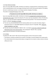
...stops output to the contact portion. Please instruct the customers on the above precautions. 4-1-10. 4-1-9. New Lithium-ion battery Each of the Types EBM 1830 and EBL 1430 lithium-ion batteries is equipped with the overdischarge protection circuit, overload protection circuit, and voltage monitoring circuit for use ...18DL/DV 14DL is changed from line contact to surface contact to minimize rattling due to about 1,500. The contact between the housing and the battery is operable. The battery is not faulty. 1 The motor may stop automatically when the remaining battery level is...
...stops output to the contact portion. Please instruct the customers on the above precautions. 4-1-10. 4-1-9. New Lithium-ion battery Each of the Types EBM 1830 and EBL 1430 lithium-ion batteries is equipped with the overdischarge protection circuit, overload protection circuit, and voltage monitoring circuit for use ...18DL/DV 14DL is changed from line contact to surface contact to minimize rattling due to about 1,500. The contact between the housing and the battery is operable. The battery is not faulty. 1 The motor may stop automatically when the remaining battery level is...
Instruction Manual
Page 20
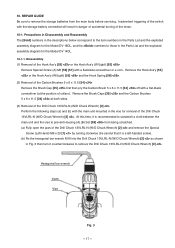
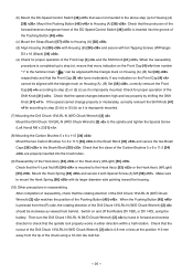
...10. Remove the Hook Ass'y [53] or the Hook Ass'y (W/Light) [55] and the Hook Spring [58] . (2) Removal of the Drill Chuck 13VLRL-N (W/O Chuck Wrench) [2] Perform the following steps (a) and (b) with the storage battery connected will result in the Parts List and the ... off with a flat-blade screwdriver or a coin. Precautions in Disassembly and Reassembly The [Bold] numbers in the descriptions below correspond to prevent Housing (A).(B) Set [38] from the main body before servicing. At this time, it counterclockwise to those in danger of accidental turning of collars). ...
...10. Remove the Hook Ass'y [53] or the Hook Ass'y (W/Light) [55] and the Hook Spring [58] . (2) Removal of the Drill Chuck 13VLRL-N (W/O Chuck Wrench) [2] Perform the following steps (a) and (b) with the storage battery connected will result in the Parts List and the ... off with a flat-blade screwdriver or a coin. Precautions in Disassembly and Reassembly The [Bold] numbers in the descriptions below correspond to prevent Housing (A).(B) Set [38] from the main body before servicing. At this time, it counterclockwise to those in danger of accidental turning of collars). ...
Instruction Manual
Page 21
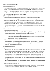
... the inside parts can be removed in an assembled or single state. Hold the Motor Spacer [30] securely and pull toward the back of Housing (B) [38] , gently remove Housing (B) [38] . Then remove the Screw Set M3 x 12 (4 pcs.) [22] that connects the Front Case [11] with a hand press. (8) Disassembly of the gear...
... the inside parts can be removed in an assembled or single state. Hold the Motor Spacer [30] securely and pull toward the back of Housing (B) [38] , gently remove Housing (B) [38] . Then remove the Screw Set M3 x 12 (4 pcs.) [22] that connects the Front Case [11] with a hand press. (8) Disassembly of the gear...
Instruction Manual
Page 28
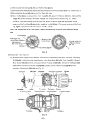
...;), the mark (i) of the Nut [6] and the marking of the main unit (a) Mount the power supply unit and the drive unit that the protrusion of Housing (A) [38] (see Fig. 17). Switch flange Marking of the Switch Plate [5] Narrow slit of the switch flange Mark (i) Wide slit of the switch ... the protrusions of the Brush Block [33] , Front Case [11] and Motor Spacer [30] with the concave portions of Housing (A) [38] , the notch of the Magnet [32] with the protrusion of Housing (A) [38] , and the groove of the Front Cap [4] with the protrusion of the Click Spring [12] is inserted ...
...;), the mark (i) of the Nut [6] and the marking of the main unit (a) Mount the power supply unit and the drive unit that the protrusion of Housing (A) [38] (see Fig. 17). Switch flange Marking of the Switch Plate [5] Narrow slit of the switch flange Mark (i) Wide slit of the switch ... the protrusions of the Brush Block [33] , Front Case [11] and Motor Spacer [30] with the concave portions of Housing (A) [38] , the notch of the Magnet [32] with the protrusion of Housing (A) [38] , and the groove of the Front Cap [4] with the protrusion of the Click Spring [12] is inserted ...
Instruction Manual
Page 29
... proper operation of the Pushing Button [45] . Switch on Housing (A). (B) Set [38] , correctly remount the Front Cap [4] according to step (3) (b) or (5) (b) as it is improperly mounted. (7) Mounting the Drill Chuck 13VLRL-N (W/O Chuck Wrench) [2] Mount the Drill Chuck 13VLRL-N (W/O Chuck Wrench) [2] to the spindle and ...(e), ensure that the protrusion of the forward/reverse changeover lever of the DC-Speed Control Switch [46] is completed up to the hammer mark " " can be aligned with Special Screw (A) M5 [59] . When the reassembly procedure is inserted into the brush tubes...
... proper operation of the Pushing Button [45] . Switch on Housing (A). (B) Set [38] , correctly remount the Front Cap [4] according to step (3) (b) or (5) (b) as it is improperly mounted. (7) Mounting the Drill Chuck 13VLRL-N (W/O Chuck Wrench) [2] Mount the Drill Chuck 13VLRL-N (W/O Chuck Wrench) [2] to the spindle and ...(e), ensure that the protrusion of the forward/reverse changeover lever of the DC-Speed Control Switch [46] is completed up to the hammer mark " " can be aligned with Special Screw (A) M5 [59] . When the reassembly procedure is inserted into the brush tubes...

Instruction Manual
Page 31
STANDARD REPAIR TIME (UNIT) SCHEDULES Variable MODEL Fixed 10 20 30 40 50 60 DV 18DL Work Flow DV 14DL General Assembly Housing (A).(B) Set Armature and Pinion Set Magnet Brush Block DC-Speed Control Switch Shift Knob Gear Box Ass'y Front Cap Drill Chuck (Keyless) Nut Spring Front Case Lock Ring Hook Ass'y Ring Gear Carrier Planet Gear (C) Set Rear Case Shift Arm Slide Ring Gear Pinion (C) Planet Gear (B) Set Pinion (B) Planet Gear (A) Set First Ring Gear --- 28 --- 11.
STANDARD REPAIR TIME (UNIT) SCHEDULES Variable MODEL Fixed 10 20 30 40 50 60 DV 18DL Work Flow DV 14DL General Assembly Housing (A).(B) Set Armature and Pinion Set Magnet Brush Block DC-Speed Control Switch Shift Knob Gear Box Ass'y Front Cap Drill Chuck (Keyless) Nut Spring Front Case Lock Ring Hook Ass'y Ring Gear Carrier Planet Gear (C) Set Rear Case Shift Arm Slide Ring Gear Pinion (C) Planet Gear (B) Set Pinion (B) Planet Gear (A) Set First Ring Gear --- 28 --- 11.
Instruction Manual
Page 33
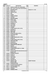
USED 1 REMARKS 2 323-898 DRILL CHUCK 13VLRL-N (W/O CHUCK WRENCH) 1 3 324-061 GEAR BOX ASS'Y 1 INCLUD. 4-11, 13-30 4 324...PAIR) 2 35 319-918 BRUSH CAP 2 36 313-687 TAPPING SCREW (W/FLANGE) D3X16 (BLACK) 10 37 NAME PLATE 1 38 326-278 HOUSING (A).(B) SET 1 39 326-279 PLATE (A) 1 40 326-276 LEVER (A) 1 41 324-137 SHIFT KNOB 1 42 326-277 LEVER (B)... CORE 1 EXCEPT FOR USA, CAN, AUS 45 322-997 PUSHING BUTTON 1 46 322-994 DC-SPEED CONTROL SWITCH 1 47 HITACHI LABEL 1 48 958-715 TAPPING SCREW D4X10 2 49 996-118 HOLDER SPRING 2 50 323-003 TERMINAL 1 51 320-997 TERMINAL...
USED 1 REMARKS 2 323-898 DRILL CHUCK 13VLRL-N (W/O CHUCK WRENCH) 1 3 324-061 GEAR BOX ASS'Y 1 INCLUD. 4-11, 13-30 4 324...PAIR) 2 35 319-918 BRUSH CAP 2 36 313-687 TAPPING SCREW (W/FLANGE) D3X16 (BLACK) 10 37 NAME PLATE 1 38 326-278 HOUSING (A).(B) SET 1 39 326-279 PLATE (A) 1 40 326-276 LEVER (A) 1 41 324-137 SHIFT KNOB 1 42 326-277 LEVER (B)... CORE 1 EXCEPT FOR USA, CAN, AUS 45 322-997 PUSHING BUTTON 1 46 322-994 DC-SPEED CONTROL SWITCH 1 47 HITACHI LABEL 1 48 958-715 TAPPING SCREW D4X10 2 49 996-118 HOLDER SPRING 2 50 323-003 TERMINAL 1 51 320-997 TERMINAL...
Instruction Manual
Page 37
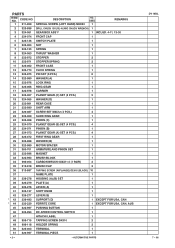
PARTS ITEM NO. USED 1 REMARKS DRILL CHUCK 13VLRL-N (W/O CHUCK WRENCH) 1 GEAR BOX ASS'Y 1 INCLUD. 4-11, 13-30 FRONT CAP 1 SWITCH PLATE 1 NUT 1 SPRING 1 THRUST WASHER 1 STOPPER 2 10 322-971 ...997 MAGNET 1 BRUSH BLOCK 1 CARBON BRUSH 5X6X11.5 (1 PAIR) 2 BRUSH CAP 2 TAPPING SCREW (W/FLANGE) D3X16 (BLACK) 10 NAME PLATE 1 HOUSING (A).(B) SET 1 PLATE (A) 1 LEVER (A) 1 SHIFT KNOB 1 LEVER (B) 1 SUPPORT (D) 1 FERRITE CORE 1 HITACHI LABEL 1 PUSHING BUTTON 1 EXCEPT FOR AUS 47 322-994 DC-SPEED CONTROL SWITCH 1 48 958-715 TAPPING SCREW D4X10 2 49 996...
PARTS ITEM NO. USED 1 REMARKS DRILL CHUCK 13VLRL-N (W/O CHUCK WRENCH) 1 GEAR BOX ASS'Y 1 INCLUD. 4-11, 13-30 FRONT CAP 1 SWITCH PLATE 1 NUT 1 SPRING 1 THRUST WASHER 1 STOPPER 2 10 322-971 ...997 MAGNET 1 BRUSH BLOCK 1 CARBON BRUSH 5X6X11.5 (1 PAIR) 2 BRUSH CAP 2 TAPPING SCREW (W/FLANGE) D3X16 (BLACK) 10 NAME PLATE 1 HOUSING (A).(B) SET 1 PLATE (A) 1 LEVER (A) 1 SHIFT KNOB 1 LEVER (B) 1 SUPPORT (D) 1 FERRITE CORE 1 HITACHI LABEL 1 PUSHING BUTTON 1 EXCEPT FOR AUS 47 322-994 DC-SPEED CONTROL SWITCH 1 48 958-715 TAPPING SCREW D4X10 2 49 996...
