
Specifications
Page 15
...circulated and filtered when the drive is electronically controlled by a microprocessor, several logic modules, digital/analog modules, and various drivers and receivers. The actuator is balanced to align the actuator in the actuator. A closed loop control. The actuator assembly...clean room environment and contains the disks and actuator assembly. 3.0 Fixed disk subsystem description 3.1 Control Electronics The drive is operational. HITACHI Deskstar & CinemaStar P7K500 Hard Disk Drive specification (Rev 1.1) 7 The control electronics performs the following major functions: • ...
...circulated and filtered when the drive is electronically controlled by a microprocessor, several logic modules, digital/analog modules, and various drivers and receivers. The actuator is balanced to align the actuator in the actuator. A closed loop control. The actuator assembly...clean room environment and contains the disks and actuator assembly. 3.0 Fixed disk subsystem description 3.1 Control Electronics The drive is operational. HITACHI Deskstar & CinemaStar P7K500 Hard Disk Drive specification (Rev 1.1) 7 The control electronics performs the following major functions: • ...
Specifications
Page 26
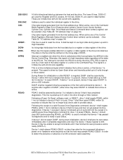
...of the Control Block Registers (Alternate Status {Device Control when written}) can be asserted by Device 1 within 1 ms to indicate to assert PDIAG-. HITACHI Deskstar & CinemaStar P7K500 Hard Disk Drive specification (Rev 1.1) 18 These are used for device 1 to drive a LED indicator. It shall be asserted... during power up to indicate that the host may assert DASP- Device 0 may assert DASP- This signal is driven by Open-Drain driver and internally pulled up to the Command Reg. within 1 ms (to indicate to select the individual register in Low logic state during ...
...of the Control Block Registers (Alternate Status {Device Control when written}) can be asserted by Device 1 within 1 ms to indicate to assert PDIAG-. HITACHI Deskstar & CinemaStar P7K500 Hard Disk Drive specification (Rev 1.1) 18 These are used for device 1 to drive a LED indicator. It shall be asserted... during power up to indicate that the host may assert DASP- Device 0 may assert DASP- This signal is driven by Open-Drain driver and internally pulled up to the Command Reg. within 1 ms (to indicate to select the individual register in Low logic state during ...
Specifications
Page 28
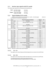
... signals that are connected to be referenced about signal specifications. Serial ATA: High Speed Serialized AT Attachment Revision 1.0a 7-January -2003 HITACHI Deskstar & CinemaStar P7K500 Hard Disk Drive specification (Rev 1.1) 20 Differential signal B from Phy S3 A- Serial data signal signal names ...Voltage Output Low Voltage 2.0 V min. 0.8 V max. 2.4 V min. 0.5 V max. 5.1.4 Signal definition(SATA model) SATA has receivers and drivers to the serial ATA cable 5.1.4.2 RX+ / RX- and Rx +/- Signal S4 Gnd 2nd mate S5 B- defines the No. These signals are the...
... signals that are connected to be referenced about signal specifications. Serial ATA: High Speed Serialized AT Attachment Revision 1.0a 7-January -2003 HITACHI Deskstar & CinemaStar P7K500 Hard Disk Drive specification (Rev 1.1) 20 Differential signal B from Phy S3 A- Serial data signal signal names ...Voltage Output Low Voltage 2.0 V min. 0.8 V max. 2.4 V min. 0.5 V max. 5.1.4 Signal definition(SATA model) SATA has receivers and drivers to the serial ATA cable 5.1.4.2 RX+ / RX- and Rx +/- Signal S4 Gnd 2nd mate S5 B- defines the No. These signals are the...
Specifications
Page 34
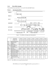
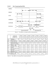
...- 0 - 0 - 0 - 0 - 0 - 0 - tAZ Maximum time allowed for output drivers to release - 10 - 10 - 10 - 10 - 10 - 10 - 10 tZAD Maximum time allowed for output drivers to -driving until the first transition of the Ultra DMA Protocol. 5.2.4.1 Initiating Read DMA DMARQ DMACKSTOP tUI... tACK tENV tACK tENV HDMARDY- timing Table 18 Ultra DMA cycle timings (Initiating Read) HITACHI Deskstar & CinemaStar P7K500 Hard ...
...- 0 - 0 - 0 - 0 - 0 - 0 - tAZ Maximum time allowed for output drivers to release - 10 - 10 - 10 - 10 - 10 - 10 - 10 tZAD Maximum time allowed for output drivers to -driving until the first transition of the Ultra DMA Protocol. 5.2.4.1 Initiating Read DMA DMARQ DMACKSTOP tUI... tACK tENV tACK tENV HDMARDY- timing Table 18 Ultra DMA cycle timings (Initiating Read) HITACHI Deskstar & CinemaStar P7K500 Hard ...
Specifications
Page 36
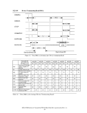
...MIN MAX MIN MAX tRFS HDMARDY- tLI Limited interlock time 0 150 0 150 0 150 0 100 0 100 0 75 0 60 tAZ Maximum time allowed for output drivers to pause time 160 - 125 - 100 - 100 - 100 - 85 - 85 - tIORDYZ Maximum time releasing IORDY before - 20 - 20 - 20 -... 20 - 20 - 20 - 20 Table 20 Ultra DMA cycle timings (Host terminating Read) HITACHI Deskstar & CinemaStar P7K500 Hard Disk Drive specification (Rev 1.1) 28 to DSTROBE time final - 75 - 70 - 60 - 60 - 60 - 50 - 50 tRP ...
...MIN MAX MIN MAX tRFS HDMARDY- tLI Limited interlock time 0 150 0 150 0 150 0 100 0 100 0 75 0 60 tAZ Maximum time allowed for output drivers to pause time 160 - 125 - 100 - 100 - 100 - 85 - 85 - tIORDYZ Maximum time releasing IORDY before - 20 - 20 - 20 -... 20 - 20 - 20 - 20 Table 20 Ultra DMA cycle timings (Host terminating Read) HITACHI Deskstar & CinemaStar P7K500 Hard Disk Drive specification (Rev 1.1) 28 to DSTROBE time final - 75 - 70 - 60 - 60 - 60 - 50 - 50 tRP ...
Specifications
Page 37
...) PARAMETER DESCRIPTION (all values in ns) Time from DSTROBE tSS edge to negation of DMARQ tLI Limited interlock time Maximum time allowed tAZ for output drivers to release tZAH Minimum delay time required for output tMLI Interlock time with minimum tCS CRC word setup time (at device side) tCH CRC word... - 0 75 - 10 20 - 20 - 5 - 5 - 20 - - 20 MODE6 MIN MAX 50 - 0 60 - 10 20 - 20 - 5 - 5 - 20 - - 20 Table 21 Ultra DMA cycle timings (Device Terminating Read) HITACHI Deskstar & CinemaStar P7K500 Hard Disk Drive specification (Rev 1.1) 29
...) PARAMETER DESCRIPTION (all values in ns) Time from DSTROBE tSS edge to negation of DMARQ tLI Limited interlock time Maximum time allowed tAZ for output drivers to release tZAH Minimum delay time required for output tMLI Interlock time with minimum tCS CRC word setup time (at device side) tCH CRC word... - 0 75 - 10 20 - 20 - 5 - 5 - 20 - - 20 MODE6 MIN MAX 50 - 0 60 - 10 20 - 20 - 5 - 5 - 20 - - 20 Table 21 Ultra DMA cycle timings (Device Terminating Read) HITACHI Deskstar & CinemaStar P7K500 Hard Disk Drive specification (Rev 1.1) 29
Specifications
Page 63
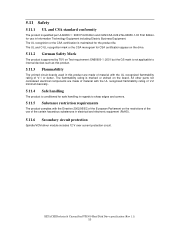
... is marked or etched on the restrictions of the use in electrical and electronic equipment (RoHS). 5.11.6 Secondary circuit protection Spindle/VCM driver module includes 12 V over current protection circuit. HITACHI Deskstar & CinemaStar P7K500 Hard Disk Drive specification (Rev 1.1) 55 All other parts not considered electrical components are made of material with...
... is marked or etched on the restrictions of the use in electrical and electronic equipment (RoHS). 5.11.6 Secondary circuit protection Spindle/VCM driver module includes 12 V over current protection circuit. HITACHI Deskstar & CinemaStar P7K500 Hard Disk Drive specification (Rev 1.1) 55 All other parts not considered electrical components are made of material with...

Specifications
Page 85
... or software reset. When the password is set . The Set Max Unlock command changes the device from protected area. Any BIOSes, device drivers, or application software access the HDD as real 6.2GB device does. 3. Set Max Unlock. The Set Max Set Password command allows the... host to define the password to the Set_Max_Unlocked mode. HITACHI Deskstar & CinemaStar P7K500 Hard Disk Drive specification (Rev 1.1) 77 Issue Read Native Max Address command to the protected area. 8.7.2 Security extensions 1....
... or software reset. When the password is set . The Set Max Unlock command changes the device from protected area. Any BIOSes, device drivers, or application software access the HDD as real 6.2GB device does. 3. Set Max Unlock. The Set Max Set Password command allows the... host to define the password to the Set_Max_Unlocked mode. HITACHI Deskstar & CinemaStar P7K500 Hard Disk Drive specification (Rev 1.1) 77 Issue Read Native Max Address command to the protected area. 8.7.2 Security extensions 1....
Specifications
Page 95
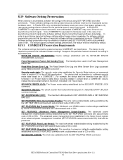
... security mode state established by default. 8.19.1 COMRESET Preservation Requirements The software settings that shall be lost without legacy driver knowledge, the software settings preservation ensures that the value of important software settings is equivalent to a different security mode state...6.13 of 55h or AAh. SET MULTIPLE MODE: The block size established with the INITIALIZE DEVICE U U PARAMETERS command. U U HITACHI Deskstar & CinemaStar P7K500 Hard Disk Drive specification (Rev 1.1) 87 SET FEATURES (Write Cache Enable/Disable): The write cache enable/disable ...
... security mode state established by default. 8.19.1 COMRESET Preservation Requirements The software settings that shall be lost without legacy driver knowledge, the software settings preservation ensures that the value of important software settings is equivalent to a different security mode state...6.13 of 55h or AAh. SET MULTIPLE MODE: The block size established with the INITIALIZE DEVICE U U PARAMETERS command. U U HITACHI Deskstar & CinemaStar P7K500 Hard Disk Drive specification (Rev 1.1) 87 SET FEATURES (Write Cache Enable/Disable): The write cache enable/disable ...


