
Specifications
Page 3
... considerations 65 8.3 Sector Addressing Mode...66 8.4 Power Management Feature 67 8.5 SMART Function ...68 8.6 Security Mode Feature Set ...70 HITACHI Deskstar & CinemaStar P7K500 Hard Disk Drive specification (Rev 1.1) ii Table of contents 1.0 General...2 1.1 Introduction...2 1.2 ... Drive organization ...9 4.5 Performance characteristics 10 5.0 Defect flagging strategy ...14 5.1 Electrical interface...15 5.2 Signal timings ...22 5.3 Jumper settings(PATA model 35 5.4 Environment ...41 5.5 DC power requirements...43 5.6 Reliability ...46 5.7 Mechanical specifications ...47 5.8 Vibration and ...
... considerations 65 8.3 Sector Addressing Mode...66 8.4 Power Management Feature 67 8.5 SMART Function ...68 8.6 Security Mode Feature Set ...70 HITACHI Deskstar & CinemaStar P7K500 Hard Disk Drive specification (Rev 1.1) ii Table of contents 1.0 General...2 1.1 Introduction...2 1.2 ... Drive organization ...9 4.5 Performance characteristics 10 5.0 Defect flagging strategy ...14 5.1 Electrical interface...15 5.2 Signal timings ...22 5.3 Jumper settings(PATA model 35 5.4 Environment ...41 5.5 DC power requirements...43 5.6 Reliability ...46 5.7 Mechanical specifications ...47 5.8 Vibration and ...

Specifications
Page 10
... Terminating Write 33 Figure 17 Jumper pin location ...35 Figure 18 Jumper pin identification...35 Figure 19 Jumper positions for normal use 37 Figure 20 Jumper positions for 15 logical head default 38 Figure 21 Jumper positions for capacity clip to 32GB 39 Figure 22 Jumper settings for Disabling Auto Spin 40 Figure...hole locations 48 Figure 26 Mounting hole locations (all dimensions are in mm 49 Figure 27 Connector locations ...50 Figure 28 Initial Setting ...71 Figure 29 Usual Operation ...72 Figure 30 Password Lost...73 Figure 31 Seek overlap ...78 Figure 32 Device address map before ...
... Terminating Write 33 Figure 17 Jumper pin location ...35 Figure 18 Jumper pin identification...35 Figure 19 Jumper positions for normal use 37 Figure 20 Jumper positions for 15 logical head default 38 Figure 21 Jumper positions for capacity clip to 32GB 39 Figure 22 Jumper settings for Disabling Auto Spin 40 Figure...hole locations 48 Figure 26 Mounting hole locations (all dimensions are in mm 49 Figure 27 Connector locations ...50 Figure 28 Initial Setting ...71 Figure 29 Usual Operation ...72 Figure 30 Password Lost...73 Figure 31 Seek overlap ...78 Figure 32 Device address map before ...
Specifications
Page 44
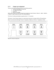
...is for a slave device that does not comply with the ATA specification. 5.3.3 Jumper pin assignment There are four jumper settings as shown in the following sections: • 16 logical head default (normal...jumper settings the pin assignment selects Device 0, Device 1, Cable or Device 1 Slave Present as shown in the following figures. The Device 1 Slave Present setting is present. Note: In conventional terminology "Device 0" designates a Master and "Device 1" designates a Slave. RSV GND I G H DS Figure 49. Jumper pin assignment GND E F CS/SP GND C D GND RSV A B RS V HITACHI...
...is for a slave device that does not comply with the ATA specification. 5.3.3 Jumper pin assignment There are four jumper settings as shown in the following sections: • 16 logical head default (normal...jumper settings the pin assignment selects Device 0, Device 1, Cable or Device 1 Slave Present as shown in the following figures. The Device 1 Slave Present setting is present. Note: In conventional terminology "Device 0" designates a Master and "Device 1" designates a Slave. RSV GND I G H DS Figure 49. Jumper pin assignment GND E F CS/SP GND C D GND RSV A B RS V HITACHI...

Specifications
Page 46
...CSEL is open or at a low level, the drive address is 1 (Device 1). To enable the CSEL mode (Cable Selection mode) the jumper block must be installed at A-C or B-D position does not affect any selection of default 16 logical head models. 5.3.4.2 15 logical head default The... figure below shows the jumper positions used to select Device 0, Device 1, Cable Selection, or Device 1 (Slave) Present setting 15 logical heads instead of Device or Cable Selection mode. HITACHI Deskstar & CinemaStar P7K500 Hard Disk Drive specification (Rev 1.1) 38 In...
...CSEL is open or at a low level, the drive address is 1 (Device 1). To enable the CSEL mode (Cable Selection mode) the jumper block must be installed at A-C or B-D position does not affect any selection of default 16 logical head models. 5.3.4.2 15 logical head default The... figure below shows the jumper positions used to select Device 0, Device 1, Cable Selection, or Device 1 (Slave) Present setting 15 logical heads instead of Device or Cable Selection mode. HITACHI Deskstar & CinemaStar P7K500 Hard Disk Drive specification (Rev 1.1) 38 In...

Specifications
Page 47
... used to select Device 0, Device 1, Cable Selection, or Device 1 (Slave) Present while setting the drive capacity down either to 32GB for capacity clip to 32GB Notes: The jumper setting acts as a 32GB clip which clips the LBA to 66055248. IGECA HFDB IGECA HFDB IGECA HFDB IGECA HFDB... DEVICE 0 (Master) DEVICE 1 (Slave) CABLE SEL DEVICE 1 (Slave) Present Figure 21 Jumper positions for the purpose of 16383/16/63. The CHS is unchanged from the factory default of compatibility. HITACHI...
... used to select Device 0, Device 1, Cable Selection, or Device 1 (Slave) Present while setting the drive capacity down either to 32GB for capacity clip to 32GB Notes: The jumper setting acts as a 32GB clip which clips the LBA to 66055248. IGECA HFDB IGECA HFDB IGECA HFDB IGECA HFDB... DEVICE 0 (Master) DEVICE 1 (Slave) CABLE SEL DEVICE 1 (Slave) Present Figure 21 Jumper positions for the purpose of 16383/16/63. The CHS is unchanged from the factory default of compatibility. HITACHI...
Specifications
Page 48
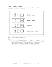
... up is 1 (Device 1). To enable the CSEL mode (Cable Selection mode) the jumper block must be installed at a high level, the drive address is SET FEATURES (subcommand 07h). HITACHI Deskstar & CinemaStar P7K500 Hard Disk Drive specification (Rev 1.1) 40 In CSEL mode, the... DEVICE 0 (Master) I GECA HFDB DEVICE 1 (Slave) IGECA HFDB CABLE SEL I GECA HFDB DEVICE 1 (Slave) Present Figure 22 Jumper settings for limiting power supply current when multiple drives are used. These jumper settings are used to select Device 0, Device 1, Cable Selection, or Device 1 (Slave) Present to 10.37...
... up is 1 (Device 1). To enable the CSEL mode (Cable Selection mode) the jumper block must be installed at a high level, the drive address is SET FEATURES (subcommand 07h). HITACHI Deskstar & CinemaStar P7K500 Hard Disk Drive specification (Rev 1.1) 40 In CSEL mode, the... DEVICE 0 (Master) I GECA HFDB DEVICE 1 (Slave) IGECA HFDB CABLE SEL I GECA HFDB DEVICE 1 (Slave) Present Figure 22 Jumper settings for limiting power supply current when multiple drives are used. These jumper settings are used to select Device 0, Device 1, Cable Selection, or Device 1 (Slave) Present to 10.37...

Specifications
Page 88
... into active state 8.12 Advanced Power Management feature set shall not be disabled via the SET FEATURES command or use of jumper. The advanced power management levels contain discrete bands, described in detail. If both Advanced Power Management and the Standby timer are correctly reported. HITACHI Deskstar & CinemaStar P7K500 Hard Disk Drive specification (Rev...
... into active state 8.12 Advanced Power Management feature set shall not be disabled via the SET FEATURES command or use of jumper. The advanced power management levels contain discrete bands, described in detail. If both Advanced Power Management and the Standby timer are correctly reported. HITACHI Deskstar & CinemaStar P7K500 Hard Disk Drive specification (Rev...


