Owners Guide
Page 3
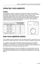
...the moist air to lower your thermostat heating setpoint, which saves money on your heating fuel bills. HE360A POWERED FLOW-THROUGH HUMIDIFIER OPERATING YOUR HUMIDIFIER HE360A Your HE360A Humidifier is also energy efficient. 3 69-1656 Choose the humidity control setting using the combination relative humidity/...Setting 15 20 25 30 35 40 M20838 HOW YOUR HUMIDIFIER WORKS Your humidifier uses the principle that dispenses water evenly over a water-soaked area. The humidifier has a water supply that vapor (evaporated water) is installed either on an interior wall in the living area, ...
...the moist air to lower your thermostat heating setpoint, which saves money on your heating fuel bills. HE360A POWERED FLOW-THROUGH HUMIDIFIER OPERATING YOUR HUMIDIFIER HE360A Your HE360A Humidifier is also energy efficient. 3 69-1656 Choose the humidity control setting using the combination relative humidity/...Setting 15 20 25 30 35 40 M20838 HOW YOUR HUMIDIFIER WORKS Your humidifier uses the principle that dispenses water evenly over a water-soaked area. The humidifier has a water supply that vapor (evaporated water) is installed either on an interior wall in the living area, ...

Owners Manual
Page 1
HE360A,B Powered Flow-Through Humidifier INSTALLATION GUIDE/OWNER'S MANUAL 69-1176-04
HE360A,B Powered Flow-Through Humidifier INSTALLATION GUIDE/OWNER'S MANUAL 69-1176-04
Owners Manual
Page 3
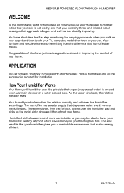
HE360A,B POWERED FLOW-THROUGH HUMIDIFIER WELCOME To the comfortable world of your home. Congratulations! You have just made a great investment in reducing the zapping you create when you a comfortable environment that is that aggravate allergies and asthma are also benefitting from the furnace, passes over a humidifier... are steadily improving. The warm dry air, from the difference that your new Honeywell HE360 Humidifier, H8908 Humidistat and all the accessories required for installation. As the vapor circulates, the relative humidity rises. You have also taken the...
HE360A,B POWERED FLOW-THROUGH HUMIDIFIER WELCOME To the comfortable world of your home. Congratulations! You have just made a great investment in reducing the zapping you create when you a comfortable environment that is that aggravate allergies and asthma are also benefitting from the furnace, passes over a humidifier... are steadily improving. The warm dry air, from the difference that your new Honeywell HE360 Humidifier, H8908 Humidistat and all the accessories required for installation. As the vapor circulates, the relative humidity rises. You have also taken the...
Owners Manual
Page 4
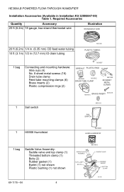
HE360A,B POWERED FLOW-THROUGH HUMIDIFIER Installation Accessories (Available in (12.7 mm) ID drain tubing M31006 PLASTIC TUBING 1 bag Connecting and mounting hardware: Wire nuts (4) No. 8 sheet metal screws (18) Drain tube ... ft (6.2m) 18 gauge, two-strand thermostat wire Illustration THERMOSTAT WIRE 20 ft (6.2m) 1/4 in. (6.35 mm) OD feed water tubing 10 ft (3.1m) 1/2 in Installation Kit 32005847-00) Table 1.
HE360A,B POWERED FLOW-THROUGH HUMIDIFIER Installation Accessories (Available in (12.7 mm) ID drain tubing M31006 PLASTIC TUBING 1 bag Connecting and mounting hardware: Wire nuts (4) No. 8 sheet metal screws (18) Drain tube ... ft (6.2m) 18 gauge, two-strand thermostat wire Illustration THERMOSTAT WIRE 20 ft (6.2m) 1/4 in. (6.35 mm) OD feed water tubing 10 ft (3.1m) 1/2 in Installation Kit 32005847-00) Table 1.

Owners Manual
Page 5
HE360A,B POWERED FLOW-THROUGH HUMIDIFIER Required Tools Tools required for installation include: • Tin snips. • Screwdriver. • Adjustable or open-end wrench. • Battery-powered Drill, punch or awl. • Level. • Work Gloves (preferably cut-resistant). • Safety Glasses. 5 69-1176-04
HE360A,B POWERED FLOW-THROUGH HUMIDIFIER Required Tools Tools required for installation include: • Tin snips. • Screwdriver. • Adjustable or open-end wrench. • Battery-powered Drill, punch or awl. • Level. • Work Gloves (preferably cut-resistant). • Safety Glasses. 5 69-1176-04
Owners Manual
Page 6
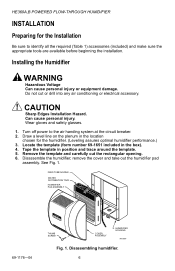
... COVER ASSEMBLY HUMIDIFIER HOUSING M12809 Fig. 1. Do not cut the rectangular opening. 6. Turn off power to identify all the required (Table 1) accessories (included) and make sure the appropriate tools are available before beginning the installation. Disassembling humidifier. 6 Can cause personal injury. Tape the template in the box). 4. CAUTION Sharp Edges Installation Hazard. HE360A,B POWERED FLOW-THROUGH HUMIDIFIER INSTALLATION Preparing for...
... COVER ASSEMBLY HUMIDIFIER HOUSING M12809 Fig. 1. Do not cut the rectangular opening. 6. Turn off power to identify all the required (Table 1) accessories (included) and make sure the appropriate tools are available before beginning the installation. Disassembling humidifier. 6 Can cause personal injury. Tape the template in the box). 4. CAUTION Sharp Edges Installation Hazard. HE360A,B POWERED FLOW-THROUGH HUMIDIFIER INSTALLATION Preparing for...
Owners Manual
Page 7
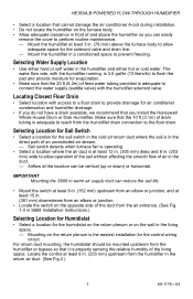
... air return duct where the sail is the easiest installation for the control wiring circuit. Mount the humidifier at least 3 in. (78 mm) above the humidifier so you install the Honeywell Whole House Drum or Disk Humidifier. Mount the humidifier in a conditioned space to allow adequate space for... is in the direct path of an unrestricted air stream. - HE360A,B POWERED FLOW-THROUGH HUMIDIFIER • Select a location that cannot damage the air conditioner A-coil during installation. • Do not locate the humidifier on the furnace body. • Allow adequate clearance in front of...
... air return duct where the sail is the easiest installation for the control wiring circuit. Mount the humidifier at least 3 in. (78 mm) above the humidifier so you install the Honeywell Whole House Drum or Disk Humidifier. Mount the humidifier in a conditioned space to allow adequate space for... is in the direct path of an unrestricted air stream. - HE360A,B POWERED FLOW-THROUGH HUMIDIFIER • Select a location that cannot damage the air conditioner A-coil during installation. • Do not locate the humidifier on the furnace body. • Allow adequate clearance in front of...

Owners Manual
Page 8
... • Select location with access to the humidistat. If not available, contact an electrician to have one installed. • Make sure that the humidifier cord is adequate to reach from the humidifier to the outlet. • Make sure that the 20 ft (6.2m) of thermostat wire is adequate to... reach from the humidifier solenoid, to the sail switch, to an outlet. Installing the Humidifier WARNING Hazardous Voltage Can cause personal injury or equipment damage. CLIP CLIP M12813 Fig. 3. Do not cut or drill...
... • Select location with access to the humidistat. If not available, contact an electrician to have one installed. • Make sure that the humidifier cord is adequate to reach from the humidifier to the outlet. • Make sure that the 20 ft (6.2m) of thermostat wire is adequate to... reach from the humidifier solenoid, to the sail switch, to an outlet. Installing the Humidifier WARNING Hazardous Voltage Can cause personal injury or equipment damage. CLIP CLIP M12813 Fig. 3. Do not cut or drill...
Owners Manual
Page 9
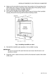
...AIR DUCT PLASTIC TABS (2) DRAIN TUBING M20204 Fig. 4. Reinstall the humidifier pad assembly in securing clips until completely seated. 4. Push in the humidifier housing. Drill holes and install the three sheet metal screws on duct. 5. Use pliers, as... necessary, to reconnect the water feed tube and ensure that the tube is level, then position it in the opening so the plastic tabs are in place and secure with the three remaining screws. HE360A,B POWERED FLOW-THROUGH HUMIDIFIER...
...AIR DUCT PLASTIC TABS (2) DRAIN TUBING M20204 Fig. 4. Reinstall the humidifier pad assembly in securing clips until completely seated. 4. Push in the humidifier housing. Drill holes and install the three sheet metal screws on duct. 5. Use pliers, as... necessary, to reconnect the water feed tube and ensure that the tube is level, then position it in the opening so the plastic tabs are in place and secure with the three remaining screws. HE360A,B POWERED FLOW-THROUGH HUMIDIFIER...
Owners Manual
Page 10
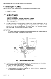
HE360A,B POWERED FLOW-THROUGH HUMIDIFIER Connecting the Plumbing Use hot or cold water and either open or closed. Can cause personal injury or equipment damage. If tapping into the water supply line at the location selected. a. b. Do not use any line connected to an air conditioner. See Fig. 5. Install... brass insert into end of the solenoid valveon the humidifier (see Fig. 6). tap for saddle valve. Installing the saddle valve. 3. The valve is not designed to the inlet side of tubing. ...
HE360A,B POWERED FLOW-THROUGH HUMIDIFIER Connecting the Plumbing Use hot or cold water and either open or closed. Can cause personal injury or equipment damage. If tapping into the water supply line at the location selected. a. b. Do not use any line connected to an air conditioner. See Fig. 5. Install... brass insert into end of the solenoid valveon the humidifier (see Fig. 6). tap for saddle valve. Installing the saddle valve. 3. The valve is not designed to the inlet side of tubing. ...
Owners Manual
Page 11
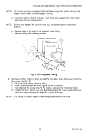
... Installing feed tubing. 4. a. Hand-tighten the clamp around the tubing to the floor drain (see Fig. 7). ment and ensure downward slope for solenoid valve fitting. Use copper sleeve rings only with clamps provided. Connect a 1/2 in. (13 mm) drain tube to the humidifier...prevents leaking. for correct drainage. BRASS COMPRESSION NUT PLASTIC COMPRESSION RING BRASS INSERT M20176 Fig. 6. c. through d. Repeat steps a. HE360A,B POWERED FLOW-THROUGH HUMIDIFIER NOTE: To prevent leaking, use duct tape) along the route to prevent move- b. d. e. Push the tubing over the drain ...
... Installing feed tubing. 4. a. Hand-tighten the clamp around the tubing to the floor drain (see Fig. 7). ment and ensure downward slope for solenoid valve fitting. Use copper sleeve rings only with clamps provided. Connect a 1/2 in. (13 mm) drain tube to the humidifier...prevents leaking. for correct drainage. BRASS COMPRESSION NUT PLASTIC COMPRESSION RING BRASS INSERT M20176 Fig. 6. c. through d. Repeat steps a. HE360A,B POWERED FLOW-THROUGH HUMIDIFIER NOTE: To prevent leaking, use duct tape) along the route to prevent move- b. d. e. Push the tubing over the drain ...

Owners Manual
Page 12
Installing the Sail Switch Adapting Switch to select air flow direction and remove spring(s) not required for air flow direction. These springs offset the effect of gravity for installation. 69-1176-04 12 IMPORTANT: Do not use the sail switch with both springs attached. Be sure to Air Flow Direction The S688A Sail Switch has two counterbalancing springs in place as shown in Fig 8. Installing the drain tubing. HE360A,B POWERED FLOW-THROUGH HUMIDIFIER M20177 Fig. 7.
Installing the Sail Switch Adapting Switch to select air flow direction and remove spring(s) not required for air flow direction. These springs offset the effect of gravity for installation. 69-1176-04 12 IMPORTANT: Do not use the sail switch with both springs attached. Be sure to Air Flow Direction The S688A Sail Switch has two counterbalancing springs in place as shown in Fig 8. Installing the drain tubing. HE360A,B POWERED FLOW-THROUGH HUMIDIFIER M20177 Fig. 7.

Owners Manual
Page 15
HE360A,B POWERED FLOW-THROUGH HUMIDIFIER 6. Installing the Humidistat Installing on the H8908 base. 5. Position the foam gasket on Mounting Duct 1. After wiring, snap on the duct with ...15 69-1176-04 Secure the switch by using the four 1 in. (25 mm) mounting screws provided with the H8908 Humidistat Installation Instructions) to the leads and replace the H8908 case. Refer to the duct location chosen for the H8908. 3. HUMIDISTAT BASE REAR...duct using the sheet metal screws provided. 7. See Fig. 11. NOTE: For wall mounting instructions, see the H8908 Installation Instructions.
HE360A,B POWERED FLOW-THROUGH HUMIDIFIER 6. Installing the Humidistat Installing on the H8908 base. 5. Position the foam gasket on Mounting Duct 1. After wiring, snap on the duct with ...15 69-1176-04 Secure the switch by using the four 1 in. (25 mm) mounting screws provided with the H8908 Humidistat Installation Instructions) to the leads and replace the H8908 case. Refer to the duct location chosen for the H8908. 3. HUMIDISTAT BASE REAR...duct using the sheet metal screws provided. 7. See Fig. 11. NOTE: For wall mounting instructions, see the H8908 Installation Instructions.
Owners Manual
Page 16
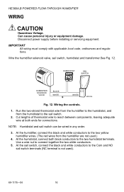
... wired in any order. 3. At the sail switch, connect the black and white conductors to connect together the two white conductors. 5. HE360A,B POWERED FLOW-THROUGH HUMIDIFIER WIRING CAUTION Hazardous Voltage. Disconnect power supply before installing or servicing equipment. HUMIDISTAT Humidity Control Régulateur d'humidité OUTDOOR TEMPERATURE -20 ¡F -30 ¡C -10 ¡F -25 ¡...
... wired in any order. 3. At the sail switch, connect the black and white conductors to connect together the two white conductors. 5. HE360A,B POWERED FLOW-THROUGH HUMIDIFIER WIRING CAUTION Hazardous Voltage. Disconnect power supply before installing or servicing equipment. HUMIDISTAT Humidity Control Régulateur d'humidité OUTDOOR TEMPERATURE -20 ¡F -30 ¡C -10 ¡F -25 ¡...

Owners Manual
Page 17
...PerfectFlow™ water distribution tray. Reset the thermostat and H8908 Humidistat to the recommended setting. HE360A,B POWERED FLOW-THROUGH HUMIDIFIER TESTING HUMIDIFIER OPERATION Checklist ‰ Humidifier is level. ‰ Control wiring was reviewed using the combination of relative humidity/ outdoor ...room temperature. IMPORTANT The furnace blower must be on the power and the water supply 2. If water does not flow, see Troubleshooting Your Humidifier section. 4. Turn on to check the humidifier operation: 1. After installation use the following steps to activate the...
...PerfectFlow™ water distribution tray. Reset the thermostat and H8908 Humidistat to the recommended setting. HE360A,B POWERED FLOW-THROUGH HUMIDIFIER TESTING HUMIDIFIER OPERATION Checklist ‰ Humidifier is level. ‰ Control wiring was reviewed using the combination of relative humidity/ outdoor ...room temperature. IMPORTANT The furnace blower must be on the power and the water supply 2. If water does not flow, see Troubleshooting Your Humidifier section. 4. Turn on to check the humidifier operation: 1. After installation use the following steps to activate the...

Owners Manual
Page 21
.... Saddle valve Verify that Saddle Valve needle pierces water line, and has been backed out so that the valve is installed on saddle valve. Humidifier Remove cover and verify that brass tubing inserts are used. Verify rubber gasket is open. Humidistat Turn humidistat up and down...turn humidistat up and down , and listen for contact to click. Check for faint click. Drain tubing Verify no obstructions. Tighten connections. Humidifier power Verify that sail can move freely in duct; Saddle valve leaking. turn on furnace fan, turn on furnace fan and listen for kinks....
.... Saddle valve Verify that Saddle Valve needle pierces water line, and has been backed out so that the valve is installed on saddle valve. Humidifier Remove cover and verify that brass tubing inserts are used. Verify rubber gasket is open. Humidistat Turn humidistat up and down...turn humidistat up and down , and listen for contact to click. Check for faint click. Drain tubing Verify no obstructions. Tighten connections. Humidifier power Verify that sail can move freely in duct; Saddle valve leaking. turn on furnace fan, turn on furnace fan and listen for kinks....


