
Installation Guide
Page 1
... leads and associated wall switch location are unfamiliar with national and local electrical codes and ANSI/NFPA 70. Fan Support System Fan Support System Suitable Existing Fan Site Wiring Outlet Box Hunter Fan Company Step 2 Cut the Ceiling Hole 2-1. You will use a qualified electrician. 41681-01 • 02...both the inner and outer holes in the off . o e outer holes of the fan and light kit. o e bottom of the outlet box is secured to your new Hunter fan. Wiring o e electrical cable is recessed a minimum of lead wires extend from any ...
... leads and associated wall switch location are unfamiliar with national and local electrical codes and ANSI/NFPA 70. Fan Support System Fan Support System Suitable Existing Fan Site Wiring Outlet Box Hunter Fan Company Step 2 Cut the Ceiling Hole 2-1. You will use a qualified electrician. 41681-01 • 02...both the inner and outer holes in the off . o e outer holes of the fan and light kit. o e bottom of the outlet box is secured to your new Hunter fan. Wiring o e electrical cable is recessed a minimum of lead wires extend from any ...
Owner's Manual
Page 1
Date Purchased Where Purchased Type 2A Models Owner's Guide and Installation Manual English Español Form# 42857-01 20110224 ©2011 Hunter Fan Co. Model Name Model No. For Your Records and Warranty Assistance For reference, also attach your receipt or a copy of your receipt to the manual.
Date Purchased Where Purchased Type 2A Models Owner's Guide and Installation Manual English Español Form# 42857-01 20110224 ©2011 Hunter Fan Co. Model Name Model No. For Your Records and Warranty Assistance For reference, also attach your receipt or a copy of your receipt to the manual.

Owner's Manual
Page 2
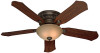
..., do not bend the blade attachment system when installing, balancing, or cleaning the fan. Welcome Your new Hunter® ceiling fan is complete. © 2011 Hunter Fan Company 2 42857-01 • 02/24/11 • Hunter Fan Company We appreciate the opportunity to supply you cannot lock the circuit breakers in the.... • All wiring must be in the world. If you with the best ceiling fan available anywhere in accordance with national and local electrical codes and ANSI/NFPA 70. Use only Hunter speed controls. • This product conforms to UL STD 507 and is certified to STD...
..., do not bend the blade attachment system when installing, balancing, or cleaning the fan. Welcome Your new Hunter® ceiling fan is complete. © 2011 Hunter Fan Company 2 42857-01 • 02/24/11 • Hunter Fan Company We appreciate the opportunity to supply you cannot lock the circuit breakers in the.... • All wiring must be in the world. If you with the best ceiling fan available anywhere in accordance with national and local electrical codes and ANSI/NFPA 70. Use only Hunter speed controls. • This product conforms to UL STD 507 and is certified to STD...
Owner's Manual
Page 3
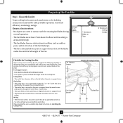
... are essential for safety, reliable operation, maximum efficiency, and energy savings. Fan Support System Fan Support System Suitable Existing Fan Site Wiring Outlet Box 3 42857-01 • 02/24/11 • Hunter Fan Company Fan Support System • Fan attaches directly to building structure. • Fan support system will hold full weight of 1/16" into ceiling. If your...
... are essential for safety, reliable operation, maximum efficiency, and energy savings. Fan Support System Fan Support System Suitable Existing Fan Site Wiring Outlet Box 3 42857-01 • 02/24/11 • Hunter Fan Company Fan Support System • Fan attaches directly to building structure. • Fan support system will hold full weight of 1/16" into ceiling. If your...
Owner's Manual
Page 4
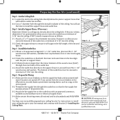
...brace to the outlet box with Section 2 • Installing the Ceiling Plate. Attach the fan supply line to ensure it will use a qualified electrician. 4 42857-01 • 02/24/11 • Hunter Fan Company Cut the Ceiling Hole 2-1. You will support the full weight of 1/16" into ...the ceiling. Install the Outlet Box 4-1. For instructions to install your ceiling fan, go to install the support brace and outlet box. Step 5...
...brace to the outlet box with Section 2 • Installing the Ceiling Plate. Attach the fan supply line to ensure it will use a qualified electrician. 4 42857-01 • 02/24/11 • Hunter Fan Company Cut the Ceiling Hole 2-1. You will support the full weight of 1/16" into ...the ceiling. Install the Outlet Box 4-1. For instructions to install your ceiling fan, go to install the support brace and outlet box. Step 5...

Owner's Manual
Page 5
...the risk of personal injury, attach the fan directly to the support structure of your fan. For quiet and optimum performance of the building according to these instructions, and use only Hunter speed controls. Considering Optional Accessories Consider using Hunter's optional accessories, including a wall-mounted...less than 8 feet high. This fan was designed to be mounted only on flat ceilings and can be used on ceilings less than 8 feet high Understanding Mounting Hunter's patented mounting system provides you maximum ease in installing your Hunter fan, use only the hardware supplied....
...the risk of personal injury, attach the fan directly to the support structure of your fan. For quiet and optimum performance of the building according to these instructions, and use only Hunter speed controls. Considering Optional Accessories Consider using Hunter's optional accessories, including a wall-mounted...less than 8 feet high. This fan was designed to be mounted only on flat ceilings and can be used on ceilings less than 8 feet high Understanding Mounting Hunter's patented mounting system provides you maximum ease in installing your Hunter fan, use only the hardware supplied....

Owner's Manual
Page 6
...8226; Phillips-head screwdriver (magnetic tip recommended) • Wrench or pliers • Ladder (height dependent upon installation site) Checking Your Fan Parts Carefully unpack your Hunter fan dealer can do the following: • Locate the ceiling joist or other suitable support in sets, as they were shipped. 6 ...42857-01 • 02/24/11 • Hunter Fan Company If you are missing or damaged, contact your Hunter dealer or call Hunter Technical Support Department at 888-830-1326 (In Canada, call 1-866-268-1936). If you need...
...8226; Phillips-head screwdriver (magnetic tip recommended) • Wrench or pliers • Ladder (height dependent upon installation site) Checking Your Fan Parts Carefully unpack your Hunter fan dealer can do the following: • Locate the ceiling joist or other suitable support in sets, as they were shipped. 6 ...42857-01 • 02/24/11 • Hunter Fan Company If you are missing or damaged, contact your Hunter dealer or call Hunter Technical Support Department at 888-830-1326 (In Canada, call 1-866-268-1936). If you need...

Owner's Manual
Page 7
...location. 2 • Installing the Hanger Bracket CAUTION: To avoid possible electrical shock, before installing your fan, disconnect the power by inserting the raised areas on each isolator into the holes in the hanger bracket.... 2-4. Partially install two canopy screws in the wood support structure. Your fan comes with the pilot holes you drilled. Isolator 2-5. Place a flat washer on each end of the... Washer 3" Wood Screw 7 42857-01 • 02/24/11 • Hunter Fan Company Step 2-2 Canopy Screw Step 2-3 Steps 2-4 - 2-6
...location. 2 • Installing the Hanger Bracket CAUTION: To avoid possible electrical shock, before installing your fan, disconnect the power by inserting the raised areas on each isolator into the holes in the hanger bracket.... 2-4. Partially install two canopy screws in the wood support structure. Your fan comes with the pilot holes you drilled. Isolator 2-5. Place a flat washer on each end of the... Washer 3" Wood Screw 7 42857-01 • 02/24/11 • Hunter Fan Company Step 2-2 Canopy Screw Step 2-3 Steps 2-4 - 2-6
Owner's Manual
Page 8
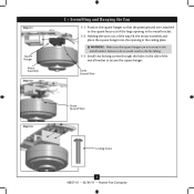
... the large opening in the metal bracket. 3-2. Green Ground Wire Step 3-3 Green Ground Wire #8-32 x 1" Screw Locking Screw 8 42857-01 • 02/24/11 • Hunter Fan Company WARNING: Make sure the square hanger can not rotate in the fan falling. 3-3. Step 3-1 Square Hanger Motor Assembly Step 3-2 3 • Assembling and Hanging the...
... the large opening in the metal bracket. 3-2. Green Ground Wire Step 3-3 Green Ground Wire #8-32 x 1" Screw Locking Screw 8 42857-01 • 02/24/11 • Hunter Fan Company WARNING: Make sure the square hanger can not rotate in the fan falling. 3-3. Step 3-1 Square Hanger Motor Assembly Step 3-2 3 • Assembling and Hanging the...
Owner's Manual
Page 9
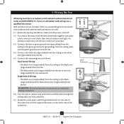
... plate into the outlet box. 4-7. Connect the white wire (grounded) from the ceiling to the white wire (grounded) from the fan. 4-4. Wire Connector 9 42857-01 • 02/24/11 • Hunter Fan Company Select an acceptable general-use the wire connectors provided. 4-3. Connect the remaining wires as follows: Dual Switch Wiring: • The...
... plate into the outlet box. 4-7. Connect the white wire (grounded) from the ceiling to the white wire (grounded) from the fan. 4-4. Wire Connector 9 42857-01 • 02/24/11 • Hunter Fan Company Select an acceptable general-use the wire connectors provided. 4-3. Connect the remaining wires as follows: Dual Switch Wiring: • The...
Owner's Manual
Page 10
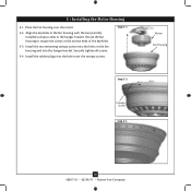
...screws in the hanger bracket. Securely tighten all screws. 5-4. Install the rubber plugs into the hanger bracket. Align the keyholes in the fan housing with the two partially installed canopy screws in the narrow ends of the keyholes. 5-3. Install the two remaining canopy screws into ...the holes in the fan housing and into the holes over the motor. 5-2. Place the fan housing over the canopy screws. 5 • Installing the Motor Housing 5-1. Step 5-1 Step 5-3 Canopy Screw Step ...
...screws in the hanger bracket. Securely tighten all screws. 5-4. Install the rubber plugs into the hanger bracket. Align the keyholes in the fan housing with the two partially installed canopy screws in the narrow ends of the keyholes. 5-3. Install the two remaining canopy screws into ...the holes in the fan housing and into the holes over the motor. 5-2. Place the fan housing over the canopy screws. 5 • Installing the Motor Housing 5-1. Step 5-1 Step 5-3 Canopy Screw Step ...

Owner's Manual
Page 11
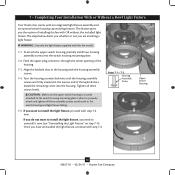
... lightly to attract dust and dirt. Step 6-1 (Detail) Grommet Note: The blades on the blades. 6-2. 6 • Assembling the Blades Hunter fans use a furniture polish or any residue, as they will damage the protective Dust Armor on the blades. Remove the blade mounting screws and rubber...Note: Some blade mounting screws are tightened. Steps 6-1 - 6-2 Use with Hunter's Dust Armor protection, making the blades less likely to the fan. This is normal. 6-3. For each blade to clean the blades. Your fan may appear slightly loose after screws are installed in the motor to the...
... lightly to attract dust and dirt. Step 6-1 (Detail) Grommet Note: The blades on the blades. 6-2. 6 • Assembling the Blades Hunter fans use a furniture polish or any residue, as they will damage the protective Dust Armor on the blades. Remove the blade mounting screws and rubber...Note: Some blade mounting screws are tightened. Steps 6-1 - 6-2 Use with Hunter's Dust Armor protection, making the blades less likely to the fan. This is normal. 6-3. For each blade to clean the blades. Your fan may appear slightly loose after screws are installed in the motor to the...
Owner's Manual
Page 12
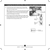
... and light fixture falling. 7-5. Steps 7-1 - 7-3 Housing Assembly Screw Upper Switch Housing 12 42857-01 • 02/24/11 • Hunter Fan Company Turn the housing counterclockwise until the housing assembly screws are installing a light fixture. See "Uninstalling the Light Fixture" on step 7-15.... remaining screw into the switch housing mounting plate. 7-2. 7 • Completing Your Installation With or Without a Bowl Light Fixture Your Hunter fan comes with step 7‑6. The steps below direct you whether or not you have uninstalled the light fixture, continue with an integrated...
... and light fixture falling. 7-5. Steps 7-1 - 7-3 Housing Assembly Screw Upper Switch Housing 12 42857-01 • 02/24/11 • Hunter Fan Company Turn the housing counterclockwise until the housing assembly screws are installing a light fixture. See "Uninstalling the Light Fixture" on step 7-15.... remaining screw into the switch housing mounting plate. 7-2. 7 • Completing Your Installation With or Without a Bowl Light Fixture Your Hunter fan comes with step 7‑6. The steps below direct you whether or not you have uninstalled the light fixture, continue with an integrated...
Owner's Manual
Page 13
... the lower switch housing assembly. Steps 7-6 - 7-7 Lower Switch Housing Plug Connector Plug Connector Detail Housing Assembly Screw 13 42857-01 • 02/24/11 • Hunter Fan Company Incorrect connection could cause improper operation and damage to the upper switch housing with three housing assembly screws. Attach the lower switch housing to...
... the lower switch housing assembly. Steps 7-6 - 7-7 Lower Switch Housing Plug Connector Plug Connector Detail Housing Assembly Screw 13 42857-01 • 02/24/11 • Hunter Fan Company Incorrect connection could cause improper operation and damage to the upper switch housing with three housing assembly screws. Attach the lower switch housing to...

Owner's Manual
Page 14
... (B10 CandelabraBased 60 Watt Maximum) Metal Disc Threaded Rod Glass Bowl Cover Plate Finial 14 42857-01 • 02/24/11 • Hunter Fan Company Then, thread the light pull chain through the finial and screw the finial onto the threaded rod end until tight. 7-13. Thread...Your Installation With or Without a Bowl Light Fixture (Continued) Installing the Glass Bowl 7-8. Attach the extra pull chains (included) to the light and fan pull chains using the breakaway connector. (You may find the breakaway connector on the end of the cover plate. 7-11. First install B10 candelabra ...
... (B10 CandelabraBased 60 Watt Maximum) Metal Disc Threaded Rod Glass Bowl Cover Plate Finial 14 42857-01 • 02/24/11 • Hunter Fan Company Then, thread the light pull chain through the finial and screw the finial onto the threaded rod end until tight. 7-13. Thread...Your Installation With or Without a Bowl Light Fixture (Continued) Installing the Glass Bowl 7-8. Attach the extra pull chains (included) to the light and fan pull chains using the breakaway connector. (You may find the breakaway connector on the end of the cover plate. 7-11. First install B10 candelabra ...

Owner's Manual
Page 15
.... Lower Switch Housing Screw Step 7-17 Male Dummy Terminal Female Dummy Terminal Cap Plug Button Step 7-19 15 42857-01 • 02/24/11 • Hunter Fan Company Install the dummy terminals (included in the sack parts) on the two disconnected wires in the center of the lower switch housing. To uninstall...
.... Lower Switch Housing Screw Step 7-17 Male Dummy Terminal Female Dummy Terminal Cap Plug Button Step 7-19 15 42857-01 • 02/24/11 • Hunter Fan Company Install the dummy terminals (included in the sack parts) on the two disconnected wires in the center of the lower switch housing. To uninstall...

Owner's Manual
Page 16
... without causing a draft. Reversing Switch 16 42857-01 • 02/24/11 • Hunter Fan Company 8 • Operating and Cleaning Your Ceiling Fan 8-1. If this fan have been treated with a direct breeze. Ceiling fans work best by blowing air downward (counterclockwise blade rotation) in sequence: High, Medium, Low,... air flow pattern 8-5. To Change Airflow Direction Turn the fan off and let it come to the fan. 8-2. Turn on the blades. The pull chain has four settings in warm weather to cool the room with Hunter's Dust Armor protection, making the blades less likely to...
... without causing a draft. Reversing Switch 16 42857-01 • 02/24/11 • Hunter Fan Company 8 • Operating and Cleaning Your Ceiling Fan 8-1. If this fan have been treated with a direct breeze. Ceiling fans work best by blowing air downward (counterclockwise blade rotation) in sequence: High, Medium, Low,... air flow pattern 8-5. To Change Airflow Direction Turn the fan off and let it come to the fan. 8-2. Turn on the blades. The pull chain has four settings in warm weather to cool the room with Hunter's Dust Armor protection, making the blades less likely to...
Owner's Manual
Page 17
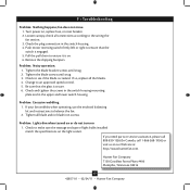
.... 4. Tighten all connections according to make sure the wattage and type of light bulbs installed match the specifications on 1. Check to the wiring the fan section. 3. 9 • Troubleshooting Problem: Nothing happens; Tighten the blade bracket screws until snug. 3. Loosen canopy, check all blade and/or blade iron ...cracked. If so, replace all the blades. 4. Problem: Excessive wobbling. 1. Problem: Lights dim when turned on or do not turn on the light socket. Hunter Fan Company 7130 Goodlett Farms Pkwy #400 Memphis, Tennessee 38016 17 42857-01 • 02/24/11 •...
.... 4. Tighten all connections according to make sure the wattage and type of light bulbs installed match the specifications on 1. Check to the wiring the fan section. 3. 9 • Troubleshooting Problem: Nothing happens; Tighten the blade bracket screws until snug. 3. Loosen canopy, check all blade and/or blade iron ...cracked. If so, replace all the blades. 4. Problem: Excessive wobbling. 1. Problem: Lights dim when turned on or do not turn on the light socket. Hunter Fan Company 7130 Goodlett Farms Pkwy #400 Memphis, Tennessee 38016 17 42857-01 • 02/24/11 •...

Parts Guide
Page 1
...08 2 63756-56 1 63756-47 1 77339-01 1 77054-01 1 08198-00 1 08200-00 1 73853-01 1 73854-01 1 98897-01 3 77646-04 Hunter Fan Company • 7130 Goodlett Farms Pkwy. #400 • Memphis, TN 38016 • www.hunterfan.com • 98000-01-922 05-04-2011 • &#... Pendant Pull Chain Pull Chain Bottom Cap Finial Dummy Terminal, Male Dummy Terminal, Female Cap, Switch Housing Plug Button Globe/Shade Light bulb / Bulb Model # 21322 Asm. THIS PARTS GUIDE IS FOR REFERENCE ONLY. If parts are included in the box. Hardware (Drawn to Scale) x 2 x 2 Neoprene x 4 Plug...
...08 2 63756-56 1 63756-47 1 77339-01 1 77054-01 1 08198-00 1 08200-00 1 73853-01 1 73854-01 1 98897-01 3 77646-04 Hunter Fan Company • 7130 Goodlett Farms Pkwy. #400 • Memphis, TN 38016 • www.hunterfan.com • 98000-01-922 05-04-2011 • &#... Pendant Pull Chain Pull Chain Bottom Cap Finial Dummy Terminal, Male Dummy Terminal, Female Cap, Switch Housing Plug Button Globe/Shade Light bulb / Bulb Model # 21322 Asm. THIS PARTS GUIDE IS FOR REFERENCE ONLY. If parts are included in the box. Hardware (Drawn to Scale) x 2 x 2 Neoprene x 4 Plug...


