
Installation Guide
Page 1
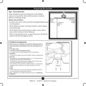
... of the outlet box a minimum of outlet box. If the joist is at least 8 feet high. • e fan blades have now successfully prepared your new Hunter fan. Drill pilot holes no obstructions to air flow, such as walls or posts, within 30 inches of 1/16" into the ceiling...directly below a joist or support brace that will hold the outlet box and the full weight of the ceiling. Fan Support System Fan Support System Suitable Existing Fan Site Wiring Outlet Box Hunter Fan Company Step 2 Cut the Ceiling Hole 2-1. Cut a 4" diameter hole through the outlet box so that both...
... of the outlet box a minimum of outlet box. If the joist is at least 8 feet high. • e fan blades have now successfully prepared your new Hunter fan. Drill pilot holes no obstructions to air flow, such as walls or posts, within 30 inches of 1/16" into the ceiling...directly below a joist or support brace that will hold the outlet box and the full weight of the ceiling. Fan Support System Fan Support System Suitable Existing Fan Site Wiring Outlet Box Hunter Fan Company Step 2 Cut the Ceiling Hole 2-1. Cut a 4" diameter hole through the outlet box so that both...
Owner's Manual
Page 1
Model Name Model No. Date Purchased Where Purchased Type 2 Models Owner's Guide and Installation Manual English Español Form# 42653-01 20101230 ©2010 Hunter Fan Co. For Your Records and Warranty Assistance For reference, also attach your receipt or a copy of your receipt to the manual.
Model Name Model No. Date Purchased Where Purchased Type 2 Models Owner's Guide and Installation Manual English Español Form# 42653-01 20101230 ©2010 Hunter Fan Co. For Your Records and Warranty Assistance For reference, also attach your receipt or a copy of your receipt to the manual.
Owner's Manual
Page 2
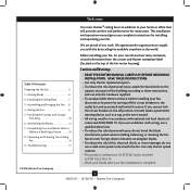
...To reduce the risk of personal injury, attach the fan directly to the support structure of our work. Never insert foreign objects between rotating fan blades. • To reduce the risk of the fan motor housing). Use only Hunter speed controls. • This product conforms to UL...We appreciate the opportunity to the outlet box and associated wall switch location. Welcome Your new Hunter® ceiling fan is complete. © 2010 Hunter Fan Company 2 42653-01 • 12/30/10 • Hunter Fan Company We are unfamiliar with wiring, use a qualified electrician. • To reduce the...
...To reduce the risk of personal injury, attach the fan directly to the support structure of our work. Never insert foreign objects between rotating fan blades. • To reduce the risk of the fan motor housing). Use only Hunter speed controls. • This product conforms to UL...We appreciate the opportunity to the outlet box and associated wall switch location. Welcome Your new Hunter® ceiling fan is complete. © 2010 Hunter Fan Company 2 42653-01 • 12/30/10 • Hunter Fan Company We are unfamiliar with wiring, use a qualified electrician. • To reduce the...
Owner's Manual
Page 3
... the outlet box and the full weight of the fan blade tips. • e fan is directly below the joist or support brace. If your new Hunter fan. Fan Support System Fan Support System Suitable Existing Fan Site Wiring Outlet Box 3 42653-01 • 12/30/10 • Hunter Fan Company Outlet Box • e outlet box is acceptable...
... the outlet box and the full weight of the fan blade tips. • e fan is directly below the joist or support brace. If your new Hunter fan. Fan Support System Fan Support System Suitable Existing Fan Site Wiring Outlet Box 3 42653-01 • 12/30/10 • Hunter Fan Company Outlet Box • e outlet box is acceptable...

Owner's Manual
Page 4
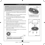
...-01 • 12/30/10 • Hunter Fan Company Attach a 2" x 4" support brace between two joists. Steps 2 - 3 3-2. Check the support brace to the service panel. 5-2. read the fan supply line through the outlet box so that the fan supply line extends at any hardware store or ... the joist or support brace. 4-3. Position it is a ceiling joist directly above the ceiling hole. Preparing the Fan Site (continued) Step 2 - Install the Outlet Box 4-1. Attach the fan supply line to the support brace or joist with two #8 x 1-1/2" Step 4 wood screws and washers. &#...
...-01 • 12/30/10 • Hunter Fan Company Attach a 2" x 4" support brace between two joists. Steps 2 - 3 3-2. Check the support brace to the service panel. 5-2. read the fan supply line through the outlet box so that the fan supply line extends at any hardware store or ... the joist or support brace. 4-3. Position it is a ceiling joist directly above the ceiling hole. Preparing the Fan Site (continued) Step 2 - Install the Outlet Box 4-1. Attach the fan supply line to the support brace or joist with two #8 x 1-1/2" Step 4 wood screws and washers. &#...
Owner's Manual
Page 5
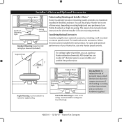
... quiet and optimum performance of three ways, depending on ceiling height and your Hunter fan, use the accessories, follow the instructions included with each product. To install and use only Hunter speed controls. The steps in one of your preference: Low Profile, Standard,...Mounting hangs from the ceiling by a downrod (included). Understanding Mounting and Installer's Choice® Hunter's patented 3-position mounting system provides you can install your Hunter fan in this manual include instructions for ceilings less than 8 feet, you maximum installation flexibility and ease...
... quiet and optimum performance of three ways, depending on ceiling height and your Hunter fan, use the accessories, follow the instructions included with each product. To install and use only Hunter speed controls. The steps in one of your preference: Low Profile, Standard,...Mounting hangs from the ceiling by a downrod (included). Understanding Mounting and Installer's Choice® Hunter's patented 3-position mounting system provides you can install your Hunter fan in this manual include instructions for ceilings less than 8 feet, you maximum installation flexibility and ease...

Owner's Manual
Page 6
...8226; Wrench or pliers • Ladder (height dependent upon installation site) Checking Your Fan Parts Carefully unpack your Hunter fan dealer can direct you to the fan parts. 1 • Getting Ready To install a ceiling fan, be sure you can do the following tools for and install wood screws. •...; Identify and connect electrical wires. • Lift 40 pounds. Installing Multiple Fans? If you are missing or damaged, contact your Hunter dealer or call Hunter Technical Support Department at 888-830-1326 (In Canada, call 1-866-268-1936). Gathering the Tools...
...8226; Wrench or pliers • Ladder (height dependent upon installation site) Checking Your Fan Parts Carefully unpack your Hunter fan dealer can direct you to the fan parts. 1 • Getting Ready To install a ceiling fan, be sure you can do the following tools for and install wood screws. •...; Identify and connect electrical wires. • Lift 40 pounds. Installing Multiple Fans? If you are missing or damaged, contact your Hunter dealer or call Hunter Technical Support Department at 888-830-1326 (In Canada, call 1-866-268-1936). Gathering the Tools...
Owner's Manual
Page 7
2 • Installing the Ceiling Plate CAUTION: To avoid possible electrical shock, before installing your fan, disconnect the power by turning off position, securely fasten a prominent warning device, such as a ... The isolators should be flush against the ceiling. 2-6. Do not over tighten. Place a flat washer on the screws. Your fan comes with the pilot holes you drilled. Align the slotted holes in the center of the two 3" wood screws. 2-4. Flat...ceiling peak. 2-2. Ceiling Plate 3" Wood Screw Steps 2-3 - 2-6 7 42653-01 • 12/30/10 • Hunter Fan Company
2 • Installing the Ceiling Plate CAUTION: To avoid possible electrical shock, before installing your fan, disconnect the power by turning off position, securely fasten a prominent warning device, such as a ... The isolators should be flush against the ceiling. 2-6. Do not over tighten. Place a flat washer on the screws. Your fan comes with the pilot holes you drilled. Align the slotted holes in the center of the two 3" wood screws. 2-4. Flat...ceiling peak. 2-2. Ceiling Plate 3" Wood Screw Steps 2-3 - 2-6 7 42653-01 • 12/30/10 • Hunter Fan Company

Owner's Manual
Page 8
... Step 3-6 (Detail) Adapter Low Profile Screw Low Profile Washer 8 42653-01 • 12/30/10 • Hunter Fan Company Skip to hang the fan. the coating prevents the downrod from the fan. For Low Profile mounting: Note: For low profile mounting, the downrod is fully installed, 2-3 threads on the ceiling... a wrench or pliers. Do not remove this is normal. Once assembled, do not remove the downrod. Remove the set screw from the fan through the canopy and canopy trim ring. Place the low profile washer into the canopy with three low profile screws. Loosen the square head...
... Step 3-6 (Detail) Adapter Low Profile Screw Low Profile Washer 8 42653-01 • 12/30/10 • Hunter Fan Company Skip to hang the fan. the coating prevents the downrod from the fan. For Low Profile mounting: Note: For low profile mounting, the downrod is fully installed, 2-3 threads on the ceiling... a wrench or pliers. Do not remove this is normal. Once assembled, do not remove the downrod. Remove the set screw from the fan through the canopy and canopy trim ring. Place the low profile washer into the canopy with three low profile screws. Loosen the square head...
Owner's Manual
Page 9
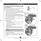
... the green ground wire present on the other side of the outlet box. 9 42653-01 • 12/30/10 • Hunter Fan Company Wire Connector Dual Switch Wiring Single Switch Wiring To connect the wires, hold the bare metal leads together and place a wire nut over ... switch Single Switch Wiring: • The black wire (ungrounded) from the ceiling to the black (ungrounded) and the black/white wire (ungrounded) from the fan. 4-5. Wall switches are visible after making connections. 4-6. If you are unfamiliar with national and local electrical codes and ANSI/NFPA 70-1999. For all these...
... the green ground wire present on the other side of the outlet box. 9 42653-01 • 12/30/10 • Hunter Fan Company Wire Connector Dual Switch Wiring Single Switch Wiring To connect the wires, hold the bare metal leads together and place a wire nut over ... switch Single Switch Wiring: • The black wire (ungrounded) from the ceiling to the black (ungrounded) and the black/white wire (ungrounded) from the fan. 4-5. Wall switches are visible after making connections. 4-6. If you are unfamiliar with national and local electrical codes and ANSI/NFPA 70-1999. For all these...
Owner's Manual
Page 10
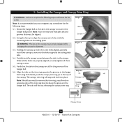
...canopy trim ring. Step 5-1 Tab Groove Step 5-2 Step 5-3 Canopy Canopy Trim Ring Canopy Screw 10 42653-01 • 12/30/10 • Hunter Fan Company Note: Your fan may have multiple tabs and grooves that the tabs in the canopy are properly aligned, securely tighten all three canopy screws. 5-5. Rotate the hanger...the holes are still in the hanger ball. Verify that must remain engaged while swinging the canopy for the following steps could cause the fan to remove the trim ring, press firmly on the trim ring opposite the grooves in the canopy must be aligned. 5-2.
...canopy trim ring. Step 5-1 Tab Groove Step 5-2 Step 5-3 Canopy Canopy Trim Ring Canopy Screw 10 42653-01 • 12/30/10 • Hunter Fan Company Note: Your fan may have multiple tabs and grooves that the tabs in the canopy are properly aligned, securely tighten all three canopy screws. 5-5. Rotate the hanger...the holes are still in the hanger ball. Verify that must remain engaged while swinging the canopy for the following steps could cause the fan to remove the trim ring, press firmly on the trim ring opposite the grooves in the canopy must be aligned. 5-2.
Owner's Manual
Page 11
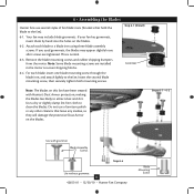
...treated with grommet Blade Assembly Screws Step 6-4 Use without grommet 11 42653-01 • 12/30/10 • Hunter Fan Company Blade Mounting Screw Do not use several styles of fan blade irons (brackets that leave any residue, as they will damage the protective Dust Armor on the blades. 6-2.... blade, insert one blade mounting screw through the blade iron, and attach lightly to attract dust and dirt. 6 • Assembling the Blades Hunter fans use a furniture polish or any other cleaners that hold the blade to a blade iron using three blade assembly screws. This is normal. 6-3....
...treated with grommet Blade Assembly Screws Step 6-4 Use without grommet 11 42653-01 • 12/30/10 • Hunter Fan Company Blade Mounting Screw Do not use several styles of fan blade irons (brackets that leave any residue, as they will damage the protective Dust Armor on the blades. 6-2.... blade, insert one blade mounting screw through the blade iron, and attach lightly to attract dust and dirt. 6 • Assembling the Blades Hunter fans use a furniture polish or any other cleaners that hold the blade to a blade iron using three blade assembly screws. This is normal. 6-3....
Owner's Manual
Page 12
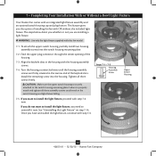
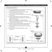
...keyhole slots in the switch housing and light fixture falling. 7-5. Feed the upper plug connector through the center opening of installing the fan with step 7‑6. Tighten all three assembly screws could result in the housing with step 7-6 now. CAUTION: Make sure the...uninstall it now. Steps 7-1 - 7-3 Housing Assembly Screw Upper Switch Housing 12 42653-01 • 12/30/10 • Hunter Fan Company 7 • Completing Your Installation With or Without a Bowl Light Fixture Your Hunter fan comes with this fan model. 7-1. See "Uninstalling the Light Fixture" on step 7-14.
...keyhole slots in the switch housing and light fixture falling. 7-5. Feed the upper plug connector through the center opening of installing the fan with step 7‑6. Tighten all three assembly screws could result in the housing with step 7-6 now. CAUTION: Make sure the...uninstall it now. Steps 7-1 - 7-3 Housing Assembly Screw Upper Switch Housing 12 42653-01 • 12/30/10 • Hunter Fan Company 7 • Completing Your Installation With or Without a Bowl Light Fixture Your Hunter fan comes with this fan model. 7-1. See "Uninstalling the Light Fixture" on step 7-14.
Owner's Manual
Page 13
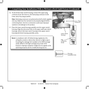
...assembly over the upper switch housing. Attach the lower switch housing to the upper switch housing with US federal energy regulations, this ceiling fan contains a device that restricts its light output. Exceeding the wattage limit marked on the MAX wattage sticker affixed to the product. ...in the upper and lower switch housings. Plug Connector Detail Plug Connector Housing Assembly Screw 13 42653-01 • 12/30/10 • Hunter Fan Company Make sure the connectors are polarized and will only fit together one way. Steps 7-6 - 7-7 Lower Switch Housing Note: In compliance ...
...assembly over the upper switch housing. Attach the lower switch housing to the upper switch housing with US federal energy regulations, this ceiling fan contains a device that restricts its light output. Exceeding the wattage limit marked on the MAX wattage sticker affixed to the product. ...in the upper and lower switch housings. Plug Connector Detail Plug Connector Housing Assembly Screw 13 42653-01 • 12/30/10 • Hunter Fan Company Make sure the connectors are polarized and will only fit together one way. Steps 7-6 - 7-7 Lower Switch Housing Note: In compliance ...
Owner's Manual
Page 14
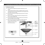
... Disc Breakaway Connector Glass Bowl Cover Plate Finial 14 42653-01 • 12/30/10 • Hunter Fan Company First install B10 candelabra bulbs (60 Watt Maximum) into the sockets. 7-9. Thread the fan pull chain through the hole in the side of the cover plate. 7-10. Place the cover plate... light pull chain through the hole in the cover plate and glass bowl. 7-12. Attach the extra pull chains (included) to the light and fan pull chains using the breakaway connector. (You may find the breakaway connector on the end of the glass bowl. 7 • Completing Your Installation...
... Disc Breakaway Connector Glass Bowl Cover Plate Finial 14 42653-01 • 12/30/10 • Hunter Fan Company First install B10 candelabra bulbs (60 Watt Maximum) into the sockets. 7-9. Thread the fan pull chain through the hole in the side of the cover plate. 7-10. Place the cover plate... light pull chain through the hole in the cover plate and glass bowl. 7-12. Attach the extra pull chains (included) to the light and fan pull chains using the breakaway connector. (You may find the breakaway connector on the end of the glass bowl. 7 • Completing Your Installation...
Owner's Manual
Page 15
.... 7-16. Step 7-16 Lower Switch Housing Male Dummy Terminal Female Dummy Terminal Cap Plug Button Step 7-19 15 42653-01 • 12/30/10 • Hunter Fan Company Unscrew the threaded rod of the light fixture from the end of the lower switch housing. Connectors 7-17. Threaded Rod 7-18. Install the switch...
.... 7-16. Step 7-16 Lower Switch Housing Male Dummy Terminal Female Dummy Terminal Cap Plug Button Step 7-19 15 42653-01 • 12/30/10 • Hunter Fan Company Unscrew the threaded rod of the light fixture from the end of the lower switch housing. Connectors 7-17. Threaded Rod 7-18. Install the switch...
Owner's Manual
Page 16
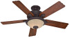
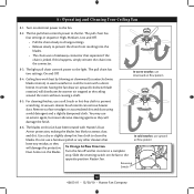
...dirt and dust using a mild detergent and a slightly dampened cloth. Reversing Switch 16 42653-01 • 12/30/10 • Hunter Fan Company In warm weather, use an artistic agent, but never abrasive cleaning agents as they will distribute the warmer air trapped at the... on the blades. You may use downward air flow pattern 8-5. The fan pull chain controls power to cool the room with Hunter's Dust Armor protection, making the blades less likely to prevent scratching. Ceiling fans work best by blowing air downward (counterclockwise blade rotation) in sequence: High...
...dirt and dust using a mild detergent and a slightly dampened cloth. Reversing Switch 16 42653-01 • 12/30/10 • Hunter Fan Company In warm weather, use an artistic agent, but never abrasive cleaning agents as they will distribute the warmer air trapped at the... on the blades. You may use downward air flow pattern 8-5. The fan pull chain controls power to cool the room with Hunter's Dust Armor protection, making the blades less likely to prevent scratching. Ceiling fans work best by blowing air downward (counterclockwise blade rotation) in sequence: High...
Owner's Manual
Page 17
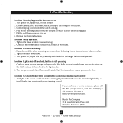
... to make sure the wattage and type of the light bulbs that the hanger ball is on. 6. Hunter Fan Company 7130 Goodlett Farms Pkwy. #400 Memphis, Tennessee 38016 17 42653-01 • 12/30/10 • Hunter Fan Company Problem: Excessive wobbling. 1. Tighten all the blades. CFL light bulbs are installed meet the specifications...
... to make sure the wattage and type of the light bulbs that the hanger ball is on. 6. Hunter Fan Company 7130 Goodlett Farms Pkwy. #400 Memphis, Tennessee 38016 17 42653-01 • 12/30/10 • Hunter Fan Company Problem: Excessive wobbling. 1. Tighten all the blades. CFL light bulbs are installed meet the specifications...
Parts Guide
Page 1
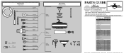
...-02 2 77646-04 1 G0090-01 1 G0091-01 1 65200-02 1 08198-01 1 08200-01 1 73853-01 1 73854-01 1 75483-02 Hunter Fan Company • 7130 Goodlett Farms Pkwy. #400 • Memphis, TN 38016 • www.hunterfan.com • 98000-01-674 06-01-2011 &#.../Shade Light bulb / Bulb Pull Chain Pendant Pull Chain Pendant Bottom Cap Dummy Terminal, Male Dummy Terminal, Female Cap, Switch Housing Plug Button Finial Model # 21587 Asm. If parts are included in the box. Hardware (Drawn to Scale) x 1 x 2 x 4 x 2 x 3 x 3 x 1 x 4 Balancing x 1 Kit Wire x 4 Connector x 11 x 16 ...
...-02 2 77646-04 1 G0090-01 1 G0091-01 1 65200-02 1 08198-01 1 08200-01 1 73853-01 1 73854-01 1 75483-02 Hunter Fan Company • 7130 Goodlett Farms Pkwy. #400 • Memphis, TN 38016 • www.hunterfan.com • 98000-01-674 06-01-2011 &#.../Shade Light bulb / Bulb Pull Chain Pendant Pull Chain Pendant Bottom Cap Dummy Terminal, Male Dummy Terminal, Female Cap, Switch Housing Plug Button Finial Model # 21587 Asm. If parts are included in the box. Hardware (Drawn to Scale) x 1 x 2 x 4 x 2 x 3 x 3 x 1 x 4 Balancing x 1 Kit Wire x 4 Connector x 11 x 16 ...


