
Installation Guide
Page 1
... o e bottom of the outlet box is at least 8 feet high. • e fan blades have now successfully prepared your ceiling fan site. Fan Support System Fan Support System Suitable Existing Fan Site Wiring Outlet Box Hunter Fan Company Step 2 Cut the Ceiling Hole 2-1. Steps 2 - 3 Step 3 Install a Support Brace, ... outlet box are turned off every item, prepare a new fan site as specified by the support brace manufacturer). o e outer holes of the fan and light kit. Locate the site for your new Hunter fan. Attach the outlet box directly to the support brace or ...
... o e bottom of the outlet box is at least 8 feet high. • e fan blades have now successfully prepared your ceiling fan site. Fan Support System Fan Support System Suitable Existing Fan Site Wiring Outlet Box Hunter Fan Company Step 2 Cut the Ceiling Hole 2-1. Steps 2 - 3 Step 3 Install a Support Brace, ... outlet box are turned off every item, prepare a new fan site as specified by the support brace manufacturer). o e outer holes of the fan and light kit. Locate the site for your new Hunter fan. Attach the outlet box directly to the support brace or ...

Owner's Manual
Page 1
Model Name Model No. Date Purchased Where Purchased Type 2 Models Owner's Guide and Installation Manual English Español Form# 45046-01 20110113 ©2011 Hunter Fan Co. For Your Records and Warranty Assistance For reference, also attach your receipt or a copy of your receipt to the manual.
Model Name Model No. Date Purchased Where Purchased Type 2 Models Owner's Guide and Installation Manual English Español Form# 45046-01 20110113 ©2011 Hunter Fan Co. For Your Records and Warranty Assistance For reference, also attach your receipt or a copy of your receipt to the manual.
Owner's Manual
Page 2
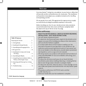
... cannot lock the circuit breakers in the world. SAVE THESE INSTRUCTIONS. • Use only Hunter replacement parts. • To reduce the risk of personal injury, attach the fan directly to your home or office that will provide comfort and performance for installing and operating ...insert foreign objects between rotating fan blades. • To reduce the risk of fire, electrical shock, or motor damage, do not bend the blade attachment system when installing, balancing, or cleaning the fan. Welcome Your new Hunter® ceiling fan is complete. © 2011 Hunter Fan Company 2 45046-01 ...
... cannot lock the circuit breakers in the world. SAVE THESE INSTRUCTIONS. • Use only Hunter replacement parts. • To reduce the risk of personal injury, attach the fan directly to your home or office that will provide comfort and performance for installing and operating ...insert foreign objects between rotating fan blades. • To reduce the risk of fire, electrical shock, or motor damage, do not bend the blade attachment system when installing, balancing, or cleaning the fan. Welcome Your new Hunter® ceiling fan is complete. © 2011 Hunter Fan Company 2 45046-01 ...
Owner's Manual
Page 3
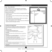
...joist or support brace by an approved connector. • Six inches of the fan and light kit. Fan Support System Fan Support System Suitable Existing Fan Site Wiring Outlet Box 3 45046-01 • 01/13/11 • Hunter Fan Company Outlet Box • e outlet box is an UL-approved octagonal ... come in contact with joist or support brace. • e bottom of 1/16" into ceiling. If your new Hunter fan. Choose the Fan Site Proper ceiling fan location and attachment to the building structure are at least 7 feet above the floor and the ceiling is at least 8 feet...
...joist or support brace by an approved connector. • Six inches of the fan and light kit. Fan Support System Fan Support System Suitable Existing Fan Site Wiring Outlet Box 3 45046-01 • 01/13/11 • Hunter Fan Company Outlet Box • e outlet box is an UL-approved octagonal ... come in contact with joist or support brace. • e bottom of 1/16" into ceiling. If your new Hunter fan. Choose the Fan Site Proper ceiling fan location and attachment to the building structure are at least 7 feet above the floor and the ceiling is at least 8 feet...
Owner's Manual
Page 4
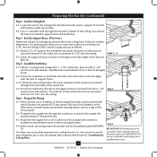
...the Outlet Box 4-1. Attach the outlet box directly to the service panel. 5-2. read the fan supply line through the outlet box so that will use a qualified electrician. 4 45046-01 • 01/13/11 • Hunter Fan Company Step 5 CAUTION: All wiring must be in accordance with two #8 x 1-1/2" Step 4... wood screws and washers. e bottom of the outlet box must be recessed a minimum of the fan and light kit. If you cannot lock the circuit...
...the Outlet Box 4-1. Attach the outlet box directly to the service panel. 5-2. read the fan supply line through the outlet box so that will use a qualified electrician. 4 45046-01 • 01/13/11 • Hunter Fan Company Step 5 CAUTION: All wiring must be in accordance with two #8 x 1-1/2" Step 4... wood screws and washers. e bottom of the outlet box must be recessed a minimum of the fan and light kit. If you cannot lock the circuit...
Owner's Manual
Page 5
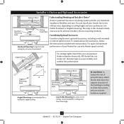
...To install and use only Hunter speed controls. For quiet and optimum performance of your Hunter fan, use the accessories, follow the instructions included with each product. All Hunter fans use only the hardware supplied. 5 45046-01 • 01/13/11 • Hunter Fan Company The steps in one ... and use sturdy 3/4" diameter pipe to the support structure of three ways, depending on ceiling height and your Hunter fan in this manual include instructions for ceilings less than 8 feet, you maximum installation flexibility and ease. Understanding Mounting and Installer's Choice...
...To install and use only Hunter speed controls. For quiet and optimum performance of your Hunter fan, use the accessories, follow the instructions included with each product. All Hunter fans use only the hardware supplied. 5 45046-01 • 01/13/11 • Hunter Fan Company The steps in one ... and use sturdy 3/4" diameter pipe to the support structure of three ways, depending on ceiling height and your Hunter fan in this manual include instructions for ceilings less than 8 feet, you maximum installation flexibility and ease. Understanding Mounting and Installer's Choice...
Owner's Manual
Page 6
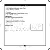
...; Phillips-head screwdriver (magnetic tip recommended) • Wrench or pliers • Ladder (height dependent upon installation site) Checking Your Fan Parts Carefully unpack your Hunter fan dealer can do the following: • Locate the ceiling joist or other suitable support in sets, as they were shipped. 6 ...45046-01 • 01/13/11 • Hunter Fan Company Refer to the motor or fan blades. Check for and install wood screws. • Identify and connect electrical wires. • Lift 40 pounds. If you...
...; Phillips-head screwdriver (magnetic tip recommended) • Wrench or pliers • Ladder (height dependent upon installation site) Checking Your Fan Parts Carefully unpack your Hunter fan dealer can do the following: • Locate the ceiling joist or other suitable support in sets, as they were shipped. 6 ...45046-01 • 01/13/11 • Hunter Fan Company Refer to the motor or fan blades. Check for and install wood screws. • Identify and connect electrical wires. • Lift 40 pounds. If you...
Owner's Manual
Page 7
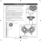
... 2-2 - 2-4 Ceiling Peak Large Opening LEFT Step 2-3 (Angled Ceiling Only) 7 45046-01 • 01/13/11 • Hunter Fan Company RIGHT Tighten the screws into the pilot holes you are installing the fan on each other. Note: Your fan comes with the pilot holes you drilled in the outlet box. Isolator Hanger Bracket 2-2. Place a flat...
... 2-2 - 2-4 Ceiling Peak Large Opening LEFT Step 2-3 (Angled Ceiling Only) 7 45046-01 • 01/13/11 • Hunter Fan Company RIGHT Tighten the screws into the pilot holes you are installing the fan on each other. Note: Your fan comes with the pilot holes you drilled in the outlet box. Isolator Hanger Bracket 2-2. Place a flat...
Owner's Manual
Page 8
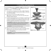
... down from a flat or angled ceiling, place the canopy and canopy trim ring around the adapter so that they rest on the fan assembly. 3-2. To assemble fan to steps 3-6 - 3-9 on the pipe will still be visible; Securely retighten the setscrew with Washer) Canopy Trim Ring Setscrew Indent... 8 45046-01 • 01/13/11 • Hunter Fan Company WARNING: Do not carry or lift fan by canopy. 3-4. Steps 3-4 - 3-5 WARNING: Fan may fall if not assembled as shown in these installation instructions. Note: Make sure all the wires are...
... down from a flat or angled ceiling, place the canopy and canopy trim ring around the adapter so that they rest on the fan assembly. 3-2. To assemble fan to steps 3-6 - 3-9 on the pipe will still be visible; Securely retighten the setscrew with Washer) Canopy Trim Ring Setscrew Indent... 8 45046-01 • 01/13/11 • Hunter Fan Company WARNING: Do not carry or lift fan by canopy. 3-4. Steps 3-4 - 3-5 WARNING: Fan may fall if not assembled as shown in these installation instructions. Note: Make sure all the wires are...
Owner's Manual
Page 9
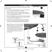
...3-7 (Detail) Low Profile Washer Adapter Canopy Trim Ring #8-32 x 3/4" Screw Step 3-10 9 45046-01 • 01/13/11 • Hunter Fan Company WARNING: Fan may fall if not assembled as shown in steps 3-1 - 3-3 on top of the canopy. Align the screw holes in the washer with the ...holes in the rim of the fan assembly. 3-9. 3 • Assembling and Hanging the Fan (Low Profile Only) You can assemble your fan for standard or angled mounting as directed in these installation instructions. Raise the...
...3-7 (Detail) Low Profile Washer Adapter Canopy Trim Ring #8-32 x 3/4" Screw Step 3-10 9 45046-01 • 01/13/11 • Hunter Fan Company WARNING: Fan may fall if not assembled as shown in steps 3-1 - 3-3 on top of the canopy. Align the screw holes in the washer with the ...holes in the rim of the fan assembly. 3-9. 3 • Assembling and Hanging the Fan (Low Profile Only) You can assemble your fan for standard or angled mounting as directed in these installation instructions. Raise the...
Owner's Manual
Page 10
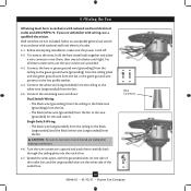
...box. 4-7. Before attempting installation, make sure the power is still off. 4-2. Wire Connector 10 45046-01 • 01/13/11 • Hunter Fan Company If you are visible after making connections. 4-6. Turn the wire connectors upward and push them , then twist clockwise until tight. Spread the...Wiring: • The black wire (ungrounded) from the ceiling to the black (ungrounded) and the black/white wire (ungrounded) from the fan CAUTION: Be sure no bare wire or wire strands are unfamiliar with national and local electrical codes. 4-1. Connect the white wire (ungrounded) ...
...box. 4-7. Before attempting installation, make sure the power is still off. 4-2. Wire Connector 10 45046-01 • 01/13/11 • Hunter Fan Company If you are visible after making connections. 4-6. Turn the wire connectors upward and push them , then twist clockwise until tight. Spread the...Wiring: • The black wire (ungrounded) from the ceiling to the black (ungrounded) and the black/white wire (ungrounded) from the fan CAUTION: Be sure no bare wire or wire strands are unfamiliar with national and local electrical codes. 4-1. Connect the white wire (ungrounded) ...
Owner's Manual
Page 11
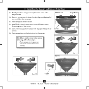
.... Twist canopy clockwise to secure the canopy. Hanger Bracket Canopy Trim Ring Step 5-4 Step 5-3 Step 5-5 Canopy Screw 11 45046-01 • 01/13/11 • Hunter Fan Company Twist canopy trim ring clockwise to secure. 5-4. Install third & fourth canopy screw in the hanger bracket. 5-2. Raise the canopy over the hanger bracket. Align...
.... Twist canopy clockwise to secure the canopy. Hanger Bracket Canopy Trim Ring Step 5-4 Step 5-3 Step 5-5 Canopy Screw 11 45046-01 • 01/13/11 • Hunter Fan Company Twist canopy trim ring clockwise to secure. 5-4. Install third & fourth canopy screw in the hanger bracket. 5-2. Raise the canopy over the hanger bracket. Align...
Owner's Manual
Page 12
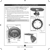
...Step 6-4 Use without grommet 12 45046-01 • 01/13/11 • Hunter Fan Company Blade Mounting Screw Steps 6-1 - 6-2 Use with Hunter's Dust Armor protection, making the blades less likely to the fan. Note: Some blade mounting screws are tightened. Remove the blade mounting screws and rubber...blades. 6-2. This is normal. 6-3. Your fan may appear slightly loose after screws are installed in the motor to the fan). 6-1. If your fan has grommets, insert them by hand into the holes on the blades. 6 • Assembling the Blades Hunter fans use a furniture polish or any other ...
...Step 6-4 Use without grommet 12 45046-01 • 01/13/11 • Hunter Fan Company Blade Mounting Screw Steps 6-1 - 6-2 Use with Hunter's Dust Armor protection, making the blades less likely to the fan. Note: Some blade mounting screws are tightened. Remove the blade mounting screws and rubber...blades. 6-2. This is normal. 6-3. Your fan may appear slightly loose after screws are installed in the motor to the fan). 6-1. If your fan has grommets, insert them by hand into the holes on the blades. 6 • Assembling the Blades Hunter fans use a furniture polish or any other ...
Owner's Manual
Page 13
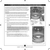
...housing and light fixture falling. 7-5. Steps 7-1 - 7-3 Housing Assembly Screw Upper Switch Housing 13 45046-01 • 01/13/11 • Hunter Fan Company Turn the housing counterclockwise until the housing assembly screws are installing a light fixture. Tighten all three assembly screws could result in the narrow ...end of the housing. 7-3. 7 • Completing Your Installation With or Without a Bowl Light Fixture Your Hunter fan comes with OR without the included light fixture. This feature gives you want to install the light fixture, proceed with this...
...housing and light fixture falling. 7-5. Steps 7-1 - 7-3 Housing Assembly Screw Upper Switch Housing 13 45046-01 • 01/13/11 • Hunter Fan Company Turn the housing counterclockwise until the housing assembly screws are installing a light fixture. Tighten all three assembly screws could result in the narrow ...end of the housing. 7-3. 7 • Completing Your Installation With or Without a Bowl Light Fixture Your Hunter fan comes with OR without the included light fixture. This feature gives you want to install the light fixture, proceed with this...
Owner's Manual
Page 14
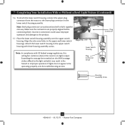
... with three housing assembly screws. Steps 7-6 - 7-7 Lower Switch Housing Plug Connector Detail Plug Connector Housing Assembly Screw 14 45046-01 • 01/13/11 • Hunter Fan Company If lights do not appear to the product. 7-7. Align the side screw holes in fire hazard or improper operation. Make sure the connectors are... attach the lower switch housing, connect the upper plug connector from the motor to the upper switch housing with US federal energy regulations, this ceiling fan contains a device that restricts its light output.
... with three housing assembly screws. Steps 7-6 - 7-7 Lower Switch Housing Plug Connector Detail Plug Connector Housing Assembly Screw 14 45046-01 • 01/13/11 • Hunter Fan Company If lights do not appear to the product. 7-7. Align the side screw holes in fire hazard or improper operation. Make sure the connectors are... attach the lower switch housing, connect the upper plug connector from the motor to the upper switch housing with US federal energy regulations, this ceiling fan contains a device that restricts its light output.
Owner's Manual
Page 15
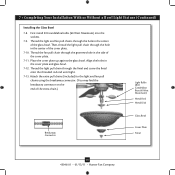
... Candelabra Base 60 Watt Maximum) Metal Rod Metal Disk Breakaway Connector Glass Bowl Cover Plate Finial 15 45046-01 • 01/13/11 • Hunter Fan Company Align the holes in the center of the cover plate. 7-10. Place the cover plate up against the glass bowl. Attach the extra pull... chains (included) to the light and fan pull chains using the breakaway connector. (You may find the breakaway connector on the end of the cover plate. 7-11. 7 • Completing Your ...
... Candelabra Base 60 Watt Maximum) Metal Rod Metal Disk Breakaway Connector Glass Bowl Cover Plate Finial 15 45046-01 • 01/13/11 • Hunter Fan Company Align the holes in the center of the cover plate. 7-10. Place the cover plate up against the glass bowl. Attach the extra pull... chains (included) to the light and fan pull chains using the breakaway connector. (You may find the breakaway connector on the end of the cover plate. 7-11. 7 • Completing Your ...
Owner's Manual
Page 16
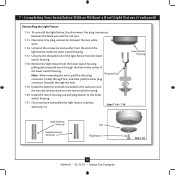
.... Steps 7-16 - 7-18 Lower Switch Housing Male Dummy Terminal Female Dummy Terminal Cap Plug Button Step 7-20 16 45046-01 • 01/13/11 • Hunter Fan Company Install the dummy terminals (included in the sack parts) on the two disconnected wires in the center of the light fixture inside the lower...
.... Steps 7-16 - 7-18 Lower Switch Housing Male Dummy Terminal Female Dummy Terminal Cap Plug Button Step 7-20 16 45046-01 • 01/13/11 • Hunter Fan Company Install the dummy terminals (included in the sack parts) on the two disconnected wires in the center of the light fixture inside the lower...
Owner's Manual
Page 17
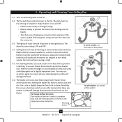
... or lint-free cloth to cool the room with Hunter's Dust Armor protection, making the blades less likely to prevent the chain from recoiling into the connector. 8-3. The chain has two settings: ON and OFF. 8-4. Ceiling fans work best by blowing air downward (counterclockwise blade rotation... 8-5. You may use upward air flow pattern 17 45046-01 • 01/13/11 • Hunter Fan Company Use a dry or slightly damp lint free cloth to a complete stop. Restart fan. Remove surface smudges or accumulated dirt and dust using a mild detergent and a slightly dampened cloth. To...
... or lint-free cloth to cool the room with Hunter's Dust Armor protection, making the blades less likely to prevent the chain from recoiling into the connector. 8-3. The chain has two settings: ON and OFF. 8-4. Ceiling fans work best by blowing air downward (counterclockwise blade rotation... 8-5. You may use upward air flow pattern 17 45046-01 • 01/13/11 • Hunter Fan Company Use a dry or slightly damp lint free cloth to a complete stop. Restart fan. Remove surface smudges or accumulated dirt and dust using a mild detergent and a slightly dampened cloth. To...
Owner's Manual
Page 18
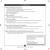
...call 1-866-268-1936) or visit us at our Web site at the wall switch. Hunter Fan Company 7130 Goodlett Farms Pkwy #400 Memphis, Tennessee 38016 18 45046-01 • 01/13/11 • Hunter Fan Company Push motor reversing switch firmly left or right to see if the blade is properly ...seated. Tighten the blade bracket screws until snug. 2. CFL light bulbs are installed meet the specifications on the MAX wattage sticker affixed to the fan off suddenly, but fan is engaged. 5....
...call 1-866-268-1936) or visit us at our Web site at the wall switch. Hunter Fan Company 7130 Goodlett Farms Pkwy #400 Memphis, Tennessee 38016 18 45046-01 • 01/13/11 • Hunter Fan Company Push motor reversing switch firmly left or right to see if the blade is properly ...seated. Tighten the blade bracket screws until snug. 2. CFL light bulbs are installed meet the specifications on the MAX wattage sticker affixed to the fan off suddenly, but fan is engaged. 5....
Parts Guide
Page 1
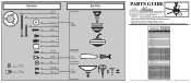
...65666-01 1 G0090-01 1 G0091-01 1 63756-18 2 63756-23 1 08198-01 1 08200-01 1 73853-01 1 73854-01 1 77646-04 Hunter Fan Company • 7130 Goodlett Farms Pkwy. #400 • Memphis, TN 38016 • www.hunterfan.com • 98000-01-979 11-16-2010 &#... Pull Chain Pendant Pull Chain Pendant Pull Chain Pull Chain Dummy Terminal, Male Dummy Terminal, Female Cap, Switch Housing Plug Button Light bulb / Bulb Model # 21711 Asm. Hardware (Drawn to Scale) x 1 x 2 x 4 x 2 x 3 x 4 x 1 x 4 Balancing x 1 Kit Wire x 4 Connector x 11 x 16 x 16 x 3 x 3 Low Profile Washer 3" ...
...65666-01 1 G0090-01 1 G0091-01 1 63756-18 2 63756-23 1 08198-01 1 08200-01 1 73853-01 1 73854-01 1 77646-04 Hunter Fan Company • 7130 Goodlett Farms Pkwy. #400 • Memphis, TN 38016 • www.hunterfan.com • 98000-01-979 11-16-2010 &#... Pull Chain Pendant Pull Chain Pendant Pull Chain Pull Chain Dummy Terminal, Male Dummy Terminal, Female Cap, Switch Housing Plug Button Light bulb / Bulb Model # 21711 Asm. Hardware (Drawn to Scale) x 1 x 2 x 4 x 2 x 3 x 4 x 1 x 4 Balancing x 1 Kit Wire x 4 Connector x 11 x 16 x 16 x 3 x 3 Low Profile Washer 3" ...


