
Owners Manual
Page 12
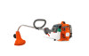
Bevel gear 4. Loop handle 8. Cylinder cover 12. Fuel tank 14. Drive disc 19. Grease filler cap 3. Operator's manual (EPA) 115275126 Rev. 1 9/15/09 English--- 12 Trimmer head 2. Shaft coupling 20. 2--stroke engine oil 21. Cutting attachment guard 5. Stop switch 10.Throttle lock--out 11. Starter handle 13. Choke control 15. Upper shaft 6. Primer bulb 16. Handle adjustment 18. Throttle control 9. Air filter cover 17. 12 4 1 KNOW YOUR TRIMMER 3 128LD 19 7 6 5 9 10 11 12 128CD 17 8 16 14 15 13 4 21 1 18 20 Know your trimmer 1. Lower shaft 7.
Bevel gear 4. Loop handle 8. Cylinder cover 12. Fuel tank 14. Drive disc 19. Grease filler cap 3. Operator's manual (EPA) 115275126 Rev. 1 9/15/09 English--- 12 Trimmer head 2. Shaft coupling 20. 2--stroke engine oil 21. Cutting attachment guard 5. Stop switch 10.Throttle lock--out 11. Starter handle 13. Choke control 15. Upper shaft 6. Primer bulb 16. Handle adjustment 18. Throttle control 9. Air filter cover 17. 12 4 1 KNOW YOUR TRIMMER 3 128LD 19 7 6 5 9 10 11 12 128CD 17 8 16 14 15 13 4 21 1 18 20 Know your trimmer 1. Lower shaft 7.

Owners Manual
Page 13
ASSEMBLY NOTE: Make sure unit is assembled correctly as shown in the diagram. S While securely holding the engine and upper shaft, pull the attachment straight out of coupling. C S Before using the unit, tighten the knob securely. S Insert hex wrench (G) in the op- ...S Loosen the coupling by turning the knob. E F G D D S Fit the drive disc (F) on the upper shaft. S Tighten the wing nut. Fitting the loop handle S Position the handle on the output shaft. Note that the handle must be used in the primary hole unless otherwise stated in the gear housing. S Fit ...
ASSEMBLY NOTE: Make sure unit is assembled correctly as shown in the diagram. S While securely holding the engine and upper shaft, pull the attachment straight out of coupling. C S Before using the unit, tighten the knob securely. S Insert hex wrench (G) in the op- ...S Loosen the coupling by turning the knob. E F G D D S Fit the drive disc (F) on the upper shaft. S Tighten the wing nut. Fitting the loop handle S Position the handle on the output shaft. Note that the handle must be used in the primary hole unless otherwise stated in the gear housing. S Fit ...

Parts List
Page 1
...19. 530015814 Description Assy - Switch Handle - Cable/Wire Harness Housing - Trigger Trigger Lockout - Lower Shaft (incl. Shield (Incl. 18,19,20,21) Limiter - Part No. 530015820 530016152 Description Bolt Wingnut Dust Cup Assy. - MODEL 128CD (US/CAN) Page: 1 1 9 2 3 4 7 8 5 6 12 13 14 10... 11 15 15 16 WARNING All repairs, adjustments and maintenance not described in the Operator's Manual must be performed by Qualified Service Personnel. 21 18 22 20 19 23 17 Ref. Driveshaft Upper (Incl. 15...
...19. 530015814 Description Assy - Switch Handle - Cable/Wire Harness Housing - Trigger Trigger Lockout - Lower Shaft (incl. Shield (Incl. 18,19,20,21) Limiter - Part No. 530015820 530016152 Description Bolt Wingnut Dust Cup Assy. - MODEL 128CD (US/CAN) Page: 1 1 9 2 3 4 7 8 5 6 12 13 14 10... 11 15 15 16 WARNING All repairs, adjustments and maintenance not described in the Operator's Manual must be performed by Qualified Service Personnel. 21 18 22 20 19 23 17 Ref. Driveshaft Upper (Incl. 15...


