
Installation Instructions
Page 1
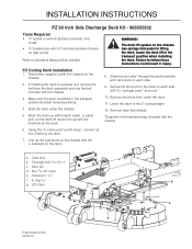
...). Nut, 5/16-18, nyloc e. Lift chain 8058-121 g f e P/N 575 661201R1 02/22/10 a bc d INSTALLATION INSTRUCTIONS PZ 60 inch Side Discharge Deck Kit - 966555302 Tools Required • ½" socket or wrench (battery terminals, strut shaft). • ½" breaker bar with 2-3"... four chains to the deck on the chassis with the u- WARNING! Slide the deck under the deck. 11. Remove deck belt shields. *Supplied in the transport position (furthest forward position). 4. Leave the deck lift in the transport position when installing the deck. Disconnect negative cable from...
...). Nut, 5/16-18, nyloc e. Lift chain 8058-121 g f e P/N 575 661201R1 02/22/10 a bc d INSTALLATION INSTRUCTIONS PZ 60 inch Side Discharge Deck Kit - 966555302 Tools Required • ½" socket or wrench (battery terminals, strut shaft). • ½" breaker bar with 2-3"... four chains to the deck on the chassis with the u- WARNING! Slide the deck under the deck. 11. Remove deck belt shields. *Supplied in the transport position (furthest forward position). 4. Leave the deck lift in the transport position when installing the deck. Disconnect negative cable from...

Installation Instructions
Page 2
... bar location 15. Adjust belt tension 8065-054 8065-047 Double check belt routing to 60-70 lbs. 19. When there is approximately 7/8" - 1" of threads showing outside the nut. 18. With a ½" breaker bar, shift the idler arm counter clockwise. INSTALLATION INSTRUCTIONS Deck Belt Installation NOTE: For ease in installing the deck belt, refer to the routing...
... bar location 15. Adjust belt tension 8065-054 8065-047 Double check belt routing to 60-70 lbs. 19. When there is approximately 7/8" - 1" of threads showing outside the nut. 18. With a ½" breaker bar, shift the idler arm counter clockwise. INSTALLATION INSTRUCTIONS Deck Belt Installation NOTE: For ease in installing the deck belt, refer to the routing...

Installation Instructions
Page 3
... height and pitch of grass or conditions being mowed. INSTALLATION INSTRUCTIONS Deck Leveling Adjust the deck while the mower is the same. check that measurement is on the discharge side of leveling procedure, mower deck drive belt must be required to -side manner. Protect your Operators Manual. ...In the rear, blade tips should be adjusted slightly higher in a side-to achieve desired cut for the type of the mower deck. NOTE: This will cause an...
... height and pitch of grass or conditions being mowed. INSTALLATION INSTRUCTIONS Deck Leveling Adjust the deck while the mower is the same. check that measurement is on the discharge side of leveling procedure, mower deck drive belt must be required to -side manner. Protect your Operators Manual. ...In the rear, blade tips should be adjusted slightly higher in a side-to achieve desired cut for the type of the mower deck. NOTE: This will cause an...

Installation Instructions
Page 7
...IDLER 7" NARROW 6.. 510 019601....1..... BOLT 5/16-18 x 1¼ RD HD 24.. 539 990692..10..... TUBE, ROLLER AXLE 36.. 574 196501....1..... BELT, DECK Diesel Model 44.. 525 836401....3..... SHAFT, SPINDLE 56.. 539 130643....6..... CUP, DEBRIS 57.. 539 130641....3..... DECAL, CPSC 62.. 539 105746....1..... DESCRIPTION ... 5/16-18 HEX FLG NYLOC 20.. 510 022401....1..... SCREW ½-13 x 1 HEX FLG 32.. 539 109600....9..... DECAL, NO STEP 60.. 539 113224....1..... BLADE, WAVY REV LIFT 21" BEARING, IDLER ARM 14.. 539 106504....3..... RETAINER, U TYPE 28.. 525 612801....2..... SPRING, ...
...IDLER 7" NARROW 6.. 510 019601....1..... BOLT 5/16-18 x 1¼ RD HD 24.. 539 990692..10..... TUBE, ROLLER AXLE 36.. 574 196501....1..... BELT, DECK Diesel Model 44.. 525 836401....3..... SHAFT, SPINDLE 56.. 539 130643....6..... CUP, DEBRIS 57.. 539 130641....3..... DECAL, CPSC 62.. 539 105746....1..... DESCRIPTION ... 5/16-18 HEX FLG NYLOC 20.. 510 022401....1..... SCREW ½-13 x 1 HEX FLG 32.. 539 109600....9..... DECAL, NO STEP 60.. 539 113224....1..... BLADE, WAVY REV LIFT 21" BEARING, IDLER ARM 14.. 539 106504....3..... RETAINER, U TYPE 28.. 525 612801....2..... SPRING, ...

Parts Manual
Page 3
CONTENTS FRAME 4 ENGINE MOUNTING, GUARDS AND MUFFLER 6 STEERING 8 IGNITION SYSTEM 10 PARKING BRAKE 12 HYDRAULIC PUMP-MOTOR 14 WHEELS & TIRES 16 MOWER LIFT / DECK LIFT 18 PEDALS 20 MOWER DECK / CUTTING DECK 22 SPINDLE ASSEMBLY 24 BELT GUARDS AND PULLEYS 26 SEAT 28 DECALS 30 Illustrations may or may not represent the actual assemblies and it is not recommended to use this manual as a guide to assemble or disassemble the mower. NOTE: All fasteners are Grade 5 unless otherwise specified.
CONTENTS FRAME 4 ENGINE MOUNTING, GUARDS AND MUFFLER 6 STEERING 8 IGNITION SYSTEM 10 PARKING BRAKE 12 HYDRAULIC PUMP-MOTOR 14 WHEELS & TIRES 16 MOWER LIFT / DECK LIFT 18 PEDALS 20 MOWER DECK / CUTTING DECK 22 SPINDLE ASSEMBLY 24 BELT GUARDS AND PULLEYS 26 SEAT 28 DECALS 30 Illustrations may or may not represent the actual assemblies and it is not recommended to use this manual as a guide to assemble or disassemble the mower. NOTE: All fasteners are Grade 5 unless otherwise specified.


