
Owners Manual
Page 2
... vehicle components contain or emit chemicals known to avoid slipping or falling, especially when operating the snow thrower in moving parts. Exercise caution to the State of the equipment. The instructions will improve footing on a trailer with a portable container.... (f) Keep the nozzle in order to operate the equipment. CONGRATULATIONS on clothing, change clothing immediately. 1. We have exposed rotating parts, which can get caught in reverse. (g) Replace gasoline cap securely and wipe up , transporting, adjusting or making repairs. Always place...
... vehicle components contain or emit chemicals known to avoid slipping or falling, especially when operating the snow thrower in moving parts. Exercise caution to the State of the equipment. The instructions will improve footing on a trailer with a portable container.... (f) Keep the nozzle in order to operate the equipment. CONGRATULATIONS on clothing, change clothing immediately. 1. We have exposed rotating parts, which can get caught in reverse. (g) Replace gasoline cap securely and wipe up , transporting, adjusting or making repairs. Always place...
Owners Manual
Page 3
...2. Open the outside doors; Never operate the snow thrower without good visibility or light. Walk; Never use a clearing tool at all moving parts have stopped rotating. 3. Always use your footing, and keep a firm hold on the handles. Keep clear of the building. Remove key...foreign object, stop the engine (motor) and check immediately for and using your snow thrower. • Follow the instructions under rotating parts. Stop the engine (motor) whenever you leave the operating position, before restarting and operating the snow thrower. Use only attachments and ...
...2. Open the outside doors; Never operate the snow thrower without good visibility or light. Walk; Never use a clearing tool at all moving parts have stopped rotating. 3. Always use your footing, and keep a firm hold on the handles. Keep clear of the building. Remove key...foreign object, stop the engine (motor) and check immediately for and using your snow thrower. • Follow the instructions under rotating parts. Stop the engine (motor) whenever you leave the operating position, before restarting and operating the snow thrower. Use only attachments and ...
Owners Manual
Page 4
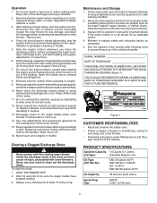
... OF CONTENTS SAFETY RULES 2-3 PRODUCT SPECIFICATIONS 3 CUSTOMER RESPONSIBILITIES 3 SAFETY AND INSTRUCTIONAL DECALS 4 ASSEMBLY 5-6 PRODUCT OVERVIEW 7 OPERATION 8-11 MAINTENANCE 12-16 STORAGE 17 TROUBLESHOOTING 18 REPAIR PARTS 20-35 WARRANTY 36-39 KNOW YOUR SNOW THROWER READ THIS OWNER'S MANUAL AND ALL SAFETY RULES BEFORE OPERATING YOUR SNOW THROWER. Compare the illustrations...
... OF CONTENTS SAFETY RULES 2-3 PRODUCT SPECIFICATIONS 3 CUSTOMER RESPONSIBILITIES 3 SAFETY AND INSTRUCTIONAL DECALS 4 ASSEMBLY 5-6 PRODUCT OVERVIEW 7 OPERATION 8-11 MAINTENANCE 12-16 STORAGE 17 TROUBLESHOOTING 18 REPAIR PARTS 20-35 WARRANTY 36-39 KNOW YOUR SNOW THROWER READ THIS OWNER'S MANUAL AND ALL SAFETY RULES BEFORE OPERATING YOUR SNOW THROWER. Compare the illustrations...
Owners Manual
Page 5
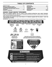
...NOTE: If handle feels unsecure with the adjustment levers closed, tighten adjustment handle nuts until the handle feels secure. 5. ASSEMBLY Setup LOOSE PARTS Use the chart below to the desired height, and close adjustment lever ensuring the positioning pin on the lower handle engages one wiring harness... place (Figure 4). Remove temporary cable ties holding cables at handle adjustment holes (Figure 2). 2. Pull up to verify that all parts have been shipped. Remove the cardboard from recoil start handle and feed the recoil rope through the rope guide. 6. Rope guide 2 4.
...NOTE: If handle feels unsecure with the adjustment levers closed, tighten adjustment handle nuts until the handle feels secure. 5. ASSEMBLY Setup LOOSE PARTS Use the chart below to the desired height, and close adjustment lever ensuring the positioning pin on the lower handle engages one wiring harness... place (Figure 4). Remove temporary cable ties holding cables at handle adjustment holes (Figure 2). 2. Pull up to verify that all parts have been shipped. Remove the cardboard from recoil start handle and feed the recoil rope through the rope guide. 6. Rope guide 2 4.

Owners Manual
Page 10
... blades, hold the control bar against the handle (Figure 13). 1 1 2 1. Control bar Figure 14 IMPORTANT: During initial operation there may be wear between these two parts (Figure 15). 1. This will cause excessive heat build up excessive heat if not operated in the auger blades which could cause damage to desired position...
... blades, hold the control bar against the handle (Figure 13). 1 1 2 1. Control bar Figure 14 IMPORTANT: During initial operation there may be wear between these two parts (Figure 15). 1. This will cause excessive heat build up excessive heat if not operated in the auger blades which could cause damage to desired position...
Owners Manual
Page 11
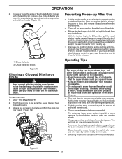
...direct sun and warming temperatures. • Slightly overlap each use your hands (Figure 19). Never use and wipe dry so it from any control or part, start button once to be removed. • Throw snow downwind whenever possible. • For extremely heavy snow, reduce the width of snow removal by... ice from the base of all objects that the auger blades could pick up . • In snowy and cold conditions, some controls and moving parts from the area of the snow thrower. • The best time to operate frozen controls. Do not use . Throwing snow during use excessive force...
...direct sun and warming temperatures. • Slightly overlap each use your hands (Figure 19). Never use and wipe dry so it from any control or part, start button once to be removed. • Throw snow downwind whenever possible. • For extremely heavy snow, reduce the width of snow removal by... ice from the base of all objects that the auger blades could pick up . • In snowy and cold conditions, some controls and moving parts from the area of the snow thrower. • The best time to operate frozen controls. Do not use . Throwing snow during use excessive force...
Owners Manual
Page 17
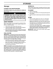
... Remove spark plug. 2. Clean entire snow thrower after adding stabilizer to allow the stabilizer to cool before storing in any enclosure. Inspect moving parts for 30 days or more. Also, alcohol blended fuels can starts to rust. Do not use . 2. WARNING: Never store the snow thrower... use plastic. SNOW THROWER When snow thrower is important to rust. Be sure that does not retain moisture. Store in essential fuel system parts such as on stabilizer container. Allow the engine to reach the carburetor. Inspect and replace belts, if necessary (See "Replaceing the Drive ...
... Remove spark plug. 2. Clean entire snow thrower after adding stabilizer to allow the stabilizer to cool before storing in any enclosure. Inspect moving parts for 30 days or more. Also, alcohol blended fuels can starts to rust. Do not use . 2. WARNING: Never store the snow thrower... use plastic. SNOW THROWER When snow thrower is important to rust. Be sure that does not retain moisture. Store in essential fuel system parts such as on stabilizer container. Allow the engine to reach the carburetor. Inspect and replace belts, if necessary (See "Replaceing the Drive ...

Owners Manual
Page 18
... not depressed. 5. Bad spark plug. 8. Vapor locked fuel line. 11. Clear blockage (ensure engine is OFF. 3. Loose parts or damaged augers or 1. Replace damaged parts. remains, contact an authorized service center/department. movement 2. Clean internal parts of replacing 5. Safety ignition key is flooded. 6. Empty fuel tank & carburetor, refill with fresh, clean gasoline. 11...
... not depressed. 5. Bad spark plug. 8. Vapor locked fuel line. 11. Clear blockage (ensure engine is OFF. 3. Loose parts or damaged augers or 1. Replace damaged parts. remains, contact an authorized service center/department. movement 2. Clean internal parts of replacing 5. Safety ignition key is flooded. 6. Empty fuel tank & carburetor, refill with fresh, clean gasoline. 11...
Owners Manual
Page 20
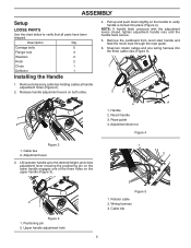
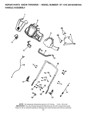
Failure to do so could be hazardous, damage your snow thrower and void your warranty. 20 inches. 1 inch = 25.4 mm IMPORTANT: Use only Original Equipment Manufacturer (O.E.M.) replacement parts. MODEL NUMBER ST 121E (96183000100) HANDLE ASSEMBLY 1 2 4 5 20 3 20 21 20 9 19 7 10 12 12 13 17 15 14 14 15 16 16 18 17 8 7 11 NOTE: All component dimensions given in U.S. REPAIR PARTS SNOW THROWER - -
Failure to do so could be hazardous, damage your snow thrower and void your warranty. 20 inches. 1 inch = 25.4 mm IMPORTANT: Use only Original Equipment Manufacturer (O.E.M.) replacement parts. MODEL NUMBER ST 121E (96183000100) HANDLE ASSEMBLY 1 2 4 5 20 3 20 21 20 9 19 7 10 12 12 13 17 15 14 14 15 16 16 18 17 8 7 11 NOTE: All component dimensions given in U.S. REPAIR PARTS SNOW THROWER - -
Owners Manual
Page 21
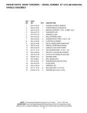
...: All component dimensions given in U.S. inches. 1 inch = 25.4 mm IMPORTANT: Use only Original Equipment Manufacturer (O.E.M.) replacement parts. Failure to do so could be hazardous, damage your snow thrower and void your warranty. 21 DCC - MODEL NUMBER ST 121E (96183000100) HANDLE ASSEMBLY KEY NO. 1 2 3 4 5 6 7 8 9 10 11 12 13 14 15 16 17 ...18 19 20 21 PART NO. 532 44 32-45 532 44 16-24 532 44 33-18 532 44 27-75...
...: All component dimensions given in U.S. inches. 1 inch = 25.4 mm IMPORTANT: Use only Original Equipment Manufacturer (O.E.M.) replacement parts. Failure to do so could be hazardous, damage your snow thrower and void your warranty. 21 DCC - MODEL NUMBER ST 121E (96183000100) HANDLE ASSEMBLY KEY NO. 1 2 3 4 5 6 7 8 9 10 11 12 13 14 15 16 17 ...18 19 20 21 PART NO. 532 44 32-45 532 44 16-24 532 44 33-18 532 44 27-75...

Owners Manual
Page 22
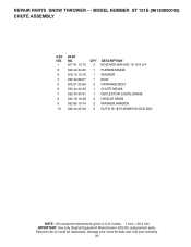
inches. 1 inch = 25.4 mm IMPORTANT: Use only Original Equipment Manufacturer (O.E.M.) replacement parts. MODEL NUMBER ST 121E (96183000100) CHUTE ASSEMBLY 8 9 10 5 4 3 7 98 6 10 10 5 2 1 NOTE: All component dimensions given in U.S. Failure to do so could be hazardous, damage your snow thrower and void your warranty. 22 REPAIR PARTS SNOW THROWER - -
inches. 1 inch = 25.4 mm IMPORTANT: Use only Original Equipment Manufacturer (O.E.M.) replacement parts. MODEL NUMBER ST 121E (96183000100) CHUTE ASSEMBLY 8 9 10 5 4 3 7 98 6 10 10 5 2 1 NOTE: All component dimensions given in U.S. Failure to do so could be hazardous, damage your snow thrower and void your warranty. 22 REPAIR PARTS SNOW THROWER - -
Owners Manual
Page 23
MODEL NUMBER ST 121E (96183000100) CHUTE ASSEMBLY KEY NO. 1 2 3 4 5 6 7 8 9 10 PART NO. 817 41 13-12 532 44 34-25 819 13 13-16 532 42 88-67 872 01 05-06 532 44 34-30 ... WASHER.HARDEN NUT.5/16-18.FLANGE.NYLOCK.BLK NOTE: All component dimensions given in U.S. inches. 1 inch = 25.4 mm IMPORTANT: Use only Original Equipment Manufacturer (O.E.M.) replacement parts. Failure to do so could be hazardous, damage your snow thrower and void your warranty. 23 REPAIR...
MODEL NUMBER ST 121E (96183000100) CHUTE ASSEMBLY KEY NO. 1 2 3 4 5 6 7 8 9 10 PART NO. 817 41 13-12 532 44 34-25 819 13 13-16 532 42 88-67 872 01 05-06 532 44 34-30 ... WASHER.HARDEN NUT.5/16-18.FLANGE.NYLOCK.BLK NOTE: All component dimensions given in U.S. inches. 1 inch = 25.4 mm IMPORTANT: Use only Original Equipment Manufacturer (O.E.M.) replacement parts. Failure to do so could be hazardous, damage your snow thrower and void your warranty. 23 REPAIR...

Owners Manual
Page 24
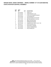
inches. 1 inch = 25.4 mm IMPORTANT: Use only Original Equipment Manufacturer (O.E.M.) replacement parts. MODEL NUMBER ST 121E (96183000100) CHUTE ROTATOR CONTROL ASSEMBLY 13 5 6 2 6 5 2 2 2 4 8 7 3 12 11 10 9 10 9 1 NOTE: All component dimensions given in U.S. Failure to do so could be hazardous, damage your snow thrower and void your warranty. 24 REPAIR PARTS SNOW THROWER - -
inches. 1 inch = 25.4 mm IMPORTANT: Use only Original Equipment Manufacturer (O.E.M.) replacement parts. MODEL NUMBER ST 121E (96183000100) CHUTE ROTATOR CONTROL ASSEMBLY 13 5 6 2 6 5 2 2 2 4 8 7 3 12 11 10 9 10 9 1 NOTE: All component dimensions given in U.S. Failure to do so could be hazardous, damage your snow thrower and void your warranty. 24 REPAIR PARTS SNOW THROWER - -
Owners Manual
Page 25
... to do so could be hazardous, damage your snow thrower and void your warranty. 25 MODEL NUMBER ST 121E (96183000100) CHUTE ROTATOR CONTROL ASSEMBLY KEY NO. 1 2 3 4 5 6 7 8 9 10 11 12 13 PART NO. 532 43 68-05 532 43 68-06 532 43 48-75 532 44 39-39 532 44 39-38 817...
... to do so could be hazardous, damage your snow thrower and void your warranty. 25 MODEL NUMBER ST 121E (96183000100) CHUTE ROTATOR CONTROL ASSEMBLY KEY NO. 1 2 3 4 5 6 7 8 9 10 11 12 13 PART NO. 532 43 68-05 532 43 68-06 532 43 48-75 532 44 39-39 532 44 39-38 817...

Owners Manual
Page 26
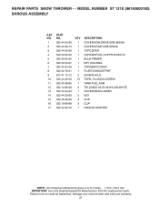
REPAIR PARTS SNOW THROWER - - Failure to do so could be hazardous, damage your snow thrower and void your warranty. 26 inches. 1 inch = 25.4 mm IMPORTANT: Use only Original Equipment Manufacturer (O.E.M.) replacement parts. MODEL NUMBER ST 121E (96183000100) SHROUD ASSEMBLY 10 1 10 10 4 10 3 5 14 17 6 7 15 10 13 15 10 2 16 16 16 10 8 9 9 10 10 10 11 12 NOTE: All component dimensions given in U.S.
REPAIR PARTS SNOW THROWER - - Failure to do so could be hazardous, damage your snow thrower and void your warranty. 26 inches. 1 inch = 25.4 mm IMPORTANT: Use only Original Equipment Manufacturer (O.E.M.) replacement parts. MODEL NUMBER ST 121E (96183000100) SHROUD ASSEMBLY 10 1 10 10 4 10 3 5 14 17 6 7 15 10 13 15 10 2 16 16 16 10 8 9 9 10 10 10 11 12 NOTE: All component dimensions given in U.S.
Owners Manual
Page 27
inches. 1 inch = 25.4 mm IMPORTANT: Use only Original Equipment Manufacturer (O.E.M.) replacement parts. REPAIR PARTS SNOW THROWER - - MODEL NUMBER ST 121E (96183000100) SHROUD ASSEMBLY KEY NO. 1 2 3 4 5 6 7 8 9 10 11 12 13 14 15 16 17 PART NO. 532 44 34-26 532 44 39-73 532 44 34-28 532 43 02-20 532 43 62-35 532...
inches. 1 inch = 25.4 mm IMPORTANT: Use only Original Equipment Manufacturer (O.E.M.) replacement parts. REPAIR PARTS SNOW THROWER - - MODEL NUMBER ST 121E (96183000100) SHROUD ASSEMBLY KEY NO. 1 2 3 4 5 6 7 8 9 10 11 12 13 14 15 16 17 PART NO. 532 44 34-26 532 44 39-73 532 44 34-28 532 43 02-20 532 43 62-35 532...
Owners Manual
Page 28
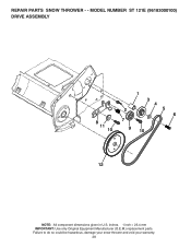
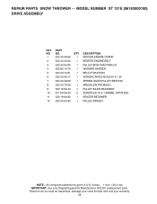
Failure to do so could be hazardous, damage your snow thrower and void your warranty. 28 REPAIR PARTS SNOW THROWER - - inches. 1 inch = 25.4 mm IMPORTANT: Use only Original Equipment Manufacturer (O.E.M.) replacement parts. MODEL NUMBER ST 121E (96183000100) DRIVE ASSEMBLY 8 11 10 1 3 4 2 5 6 7 9 10 12 NOTE: All component dimensions given in U.S.
Failure to do so could be hazardous, damage your snow thrower and void your warranty. 28 REPAIR PARTS SNOW THROWER - - inches. 1 inch = 25.4 mm IMPORTANT: Use only Original Equipment Manufacturer (O.E.M.) replacement parts. MODEL NUMBER ST 121E (96183000100) DRIVE ASSEMBLY 8 11 10 1 3 4 2 5 6 7 9 10 12 NOTE: All component dimensions given in U.S.
Owners Manual
Page 29
MODEL NUMBER ST 121E (96183000100) DRIVE ASSEMBLY KEY NO. 1 2 3 4 5 6 7 8 9 10 11 12 PART NO. 532 43 48-60 532 43 45-02 532 42 64-90 532 85 10-74 532 43 72-61 532 43 08-17 ... PULLEY.DRIVEN NOTE: All component dimensions given in U.S. Failure to do so could be hazardous, damage your snow thrower and void your warranty. 29 REPAIR PARTS SNOW THROWER - - inches. 1 inch = 25.4 mm IMPORTANT: Use only Original Equipment Manufacturer (O.E.M.) replacement...
MODEL NUMBER ST 121E (96183000100) DRIVE ASSEMBLY KEY NO. 1 2 3 4 5 6 7 8 9 10 11 12 PART NO. 532 43 48-60 532 43 45-02 532 42 64-90 532 85 10-74 532 43 72-61 532 43 08-17 ... PULLEY.DRIVEN NOTE: All component dimensions given in U.S. Failure to do so could be hazardous, damage your snow thrower and void your warranty. 29 REPAIR PARTS SNOW THROWER - - inches. 1 inch = 25.4 mm IMPORTANT: Use only Original Equipment Manufacturer (O.E.M.) replacement...

Owners Manual
Page 30
inches. 1 inch = 25.4 mm IMPORTANT: Use only Original Equipment Manufacturer (O.E.M.) replacement parts. MODEL NUMBER ST 121E (96183000100) FRAME ASSEMBLY 11 1 4 3 2 15 14 15 8 8 8 9 6 12 7 12 6 13 7 12 7 10 5 3 4 NOTE: All component dimensions given in U.S. Failure to do so could be hazardous, damage your snow thrower and void your warranty. 30 REPAIR PARTS SNOW THROWER - -
inches. 1 inch = 25.4 mm IMPORTANT: Use only Original Equipment Manufacturer (O.E.M.) replacement parts. MODEL NUMBER ST 121E (96183000100) FRAME ASSEMBLY 11 1 4 3 2 15 14 15 8 8 8 9 6 12 7 12 6 13 7 12 7 10 5 3 4 NOTE: All component dimensions given in U.S. Failure to do so could be hazardous, damage your snow thrower and void your warranty. 30 REPAIR PARTS SNOW THROWER - -

Owners Manual
Page 31
MODEL NUMBER ST 121E (96183000100) FRAME ASSEMBLY KEY NO. 1 2 3 4 5 6 7 8 9 10 11 12 13 14 15 PART NO. 532 44 21-59 532 44 47-23 532 44 ...44 22-50 QTY 1 1 2 2 2 2 3 3 1 2 1 3 1 1 4 DESCRIPTION ENGINE.208.LCT.ESTRT.W/ALT FRAME.WELDMENT.SSST WHEEL.HUSQVARNA NUT.PUSH.AXLE.0.5IN SCREW.5/16-24 X 2.00"HHCS BOLT.ENG. 3/8-16 X 1.280 NUT.HEX.FLANGE.1/4-20.CTR.LOCK BOLT.RDHD.SQNK.1/4-20 UNC ...REAR.FRAME TORX.1/4-20 X 3/4.SCREW NOTE: All component dimensions given in U.S. REPAIR PARTS SNOW THROWER - - inches. 1 inch = 25.4 mm IMPORTANT: Use only Original Equipment Manufacturer (O.E.M.) replacement...
MODEL NUMBER ST 121E (96183000100) FRAME ASSEMBLY KEY NO. 1 2 3 4 5 6 7 8 9 10 11 12 13 14 15 PART NO. 532 44 21-59 532 44 47-23 532 44 ...44 22-50 QTY 1 1 2 2 2 2 3 3 1 2 1 3 1 1 4 DESCRIPTION ENGINE.208.LCT.ESTRT.W/ALT FRAME.WELDMENT.SSST WHEEL.HUSQVARNA NUT.PUSH.AXLE.0.5IN SCREW.5/16-24 X 2.00"HHCS BOLT.ENG. 3/8-16 X 1.280 NUT.HEX.FLANGE.1/4-20.CTR.LOCK BOLT.RDHD.SQNK.1/4-20 UNC ...REAR.FRAME TORX.1/4-20 X 3/4.SCREW NOTE: All component dimensions given in U.S. REPAIR PARTS SNOW THROWER - - inches. 1 inch = 25.4 mm IMPORTANT: Use only Original Equipment Manufacturer (O.E.M.) replacement...


