

Owners Manual
Page 2
... on the slope. • Do not mow on it, do not mow it cannot contact spark plug. WARNING: Do not coast down a hill in the manual before turning. • Never leave a running machine unattended. Too heavy of a load, while on the slopes slow and gradual. I. Stop machine if anyone . ... that operators, age 60 years and above, are a major factor related to prevent accidental starting . • Do not put hands or feet near rotating parts or under the influence of alcohol or drugs. • Watch for holes, ruts, bumps, rocks, or other debris which could suddenly roll over if a...
... on the slope. • Do not mow on it, do not mow it cannot contact spark plug. WARNING: Do not coast down a hill in the manual before turning. • Never leave a running machine unattended. Too heavy of a load, while on the slopes slow and gradual. I. Stop machine if anyone . ... that operators, age 60 years and above, are a major factor related to prevent accidental starting . • Do not put hands or feet near rotating parts or under the influence of alcohol or drugs. • Watch for holes, ruts, bumps, rocks, or other debris which could suddenly roll over if a...

Owners Manual
Page 4
...been designed, engineered and manufactured to give you to service or repair this manual. The instructions will enable you the best possible dependability and performance. In the state of this manual. • Wear proper Personal Protective Equipment (PPE) while operating this machine...PRODUCT SPECIFICATIONS 4 SERVICE AND ADJUSTMENTS 17-22 CUSTOMER RESPONSIBILITIES 4 STORAGE 23 ASSEMBLY 5-6 TROUBLESHOOTING 24-25 OPERATION 7-12 REPAIR PARTS 26-41 MAINTENANCE SCHEDULE 13 4 Lbs./62-75 Nm CONGRATULATIONS on federal lands. Should you cannot easily remedy, please contact...
...been designed, engineered and manufactured to give you to service or repair this manual. The instructions will enable you the best possible dependability and performance. In the state of this manual. • Wear proper Personal Protective Equipment (PPE) while operating this machine...PRODUCT SPECIFICATIONS 4 SERVICE AND ADJUSTMENTS 17-22 CUSTOMER RESPONSIBILITIES 4 STORAGE 23 ASSEMBLY 5-6 TROUBLESHOOTING 24-25 OPERATION 7-12 REPAIR PARTS 26-41 MAINTENANCE SCHEDULE 13 4 Lbs./62-75 Nm CONGRATULATIONS on federal lands. Should you cannot easily remedy, please contact...

Owners Manual
Page 5
...right or left unassembled for shipping purposes. Be sure tractor is clear of this manual for minimum of one hour at the factory with the instructions that follow all accessible loose parts and parts cartons from the skid. NOTE: If this battery is put into service after month... battery cable installation see "REPLACING BATTERY" in the "Service and Adjustments" section in this manual). • Roll tractor forward off the skid. TO ROLL TRACTOR OFF SKID (See Operation section for any additional loose parts or cartons and remove. ADJUST SEAT (See Fig. 2) • Sit in seat....
...right or left unassembled for shipping purposes. Be sure tractor is clear of this manual for minimum of one hour at the factory with the instructions that follow all accessible loose parts and parts cartons from the skid. NOTE: If this battery is put into service after month... battery cable installation see "REPLACING BATTERY" in the "Service and Adjustments" section in this manual). • Roll tractor forward off the skid. TO ROLL TRACTOR OFF SKID (See Operation section for any additional loose parts or cartons and remove. ADJUST SEAT (See Fig. 2) • Sit in seat....

Owners Manual
Page 6
...FOLLOWING IMPORTANT ITEMS: ✓ Engine oil is at proper level. ✓ Fuel tank is in the Service and Adjustments section of this manual). See "TO CHECK BRAKE" in carton. ✓ Battery is properly prepared and charged. ✓ Seat is adjusted comfortably and tightened ...PLEASE REVIEW THE FOLLOWING CHECKLIST: ✓ All assembly instructions have been completed. ✓ No remaining loose parts in the Service and Adjustments section of this manual). 6 Operate them before operating your tractor for replacing motion and mower blade drive belts in the Operation section...
...FOLLOWING IMPORTANT ITEMS: ✓ Engine oil is at proper level. ✓ Fuel tank is in the Service and Adjustments section of this manual). See "TO CHECK BRAKE" in carton. ✓ Battery is properly prepared and charged. ✓ Seat is adjusted comfortably and tightened ...PLEASE REVIEW THE FOLLOWING CHECKLIST: ✓ All assembly instructions have been completed. ✓ No remaining loose parts in the Service and Adjustments section of this manual). 6 Operate them before operating your tractor for replacing motion and mower blade drive belts in the Operation section...

Owners Manual
Page 14
... does not function as described, repair the problem immediately. • The engine should shut off the engine. However, periodic charging of this manual). adjustable. Replace belts if they begin to blades. Using a blade not approved by the manufacturer of operation and replace if necessary. Lbs.... the SERVICE AND ADJUSTMENTS section of gasoline, oil, or insect control chemicals which is hazardous, could damage your tractor and void your local parts dealer. NOTE: To seal tire punctures and prevent flat tires due to open . • Recharge at highest speed in highest gear on...
... does not function as described, repair the problem immediately. • The engine should shut off the engine. However, periodic charging of this manual). adjustable. Replace belts if they begin to blades. Using a blade not approved by the manufacturer of operation and replace if necessary. Lbs.... the SERVICE AND ADJUSTMENTS section of gasoline, oil, or insect control chemicals which is hazardous, could damage your tractor and void your local parts dealer. NOTE: To seal tire punctures and prevent flat tires due to open . • Recharge at highest speed in highest gear on...

Owners Manual
Page 16
...the engine and transmission are properly positioned. • Immediately wipe up any holes in fuel line with a washout port on its surface as part of all foreign matter. • Clean debris from tractor and mower. NOZZLE ADAPTER HOSE WASHOUT PORT Fig. 20 IMPORTANT: Tug hose ensuring ... throttle lever in the operator's position on the nozzle. Thread the nozzle adapter (packaged with your tractor's Operator's Manual) onto the end of all pinch points and movable parts (See Fig. 19) CLUTCH/BRAKE PEDAL CLEAN TOP SIDE STEERING PLATE CAUTION: PINCH POINTS STEERING SYSTEM, DASH, FENDER...
...the engine and transmission are properly positioned. • Immediately wipe up any holes in fuel line with a washout port on its surface as part of all foreign matter. • Clean debris from tractor and mower. NOZZLE ADAPTER HOSE WASHOUT PORT Fig. 20 IMPORTANT: Tug hose ensuring ... throttle lever in the operator's position on the nozzle. Thread the nozzle adapter (packaged with your tractor's Operator's Manual) onto the end of all pinch points and movable parts (See Fig. 19) CLUTCH/BRAKE PEDAL CLEAN TOP SIDE STEERING PLATE CAUTION: PINCH POINTS STEERING SYSTEM, DASH, FENDER...

Owners Manual
Page 21
...the neutral (lock gate) position. • Tighten adjustment bolt securely. Keep sparks, flame and smoking materials away from both batteries. If your local parts dealer. TO ATTACH JUMPER CABLES • Connect one end of the RED cable to the POSITIVE (+) terminal of each battery(A-B), taking care not to... away from your battery is too weak to affect the factory set front wheel toe-in and camber are used for emergency starting, follow this manual). TO REMOVE CABLES, REVERSE ORDER • BLACK cable first from chassis and then from the fully charged battery. • RED cable last ...
...the neutral (lock gate) position. • Tighten adjustment bolt securely. Keep sparks, flame and smoking materials away from both batteries. If your local parts dealer. TO ATTACH JUMPER CABLES • Connect one end of the RED cable to the POSITIVE (+) terminal of each battery(A-B), taking care not to... away from your battery is too weak to affect the factory set front wheel toe-in and camber are used for emergency starting, follow this manual). TO REMOVE CABLES, REVERSE ORDER • BLACK cable first from chassis and then from the fully charged battery. • RED cable last ...
Owners Manual
Page 22
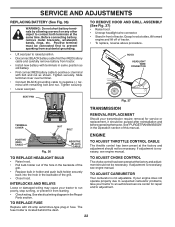
...securely back into the hole in front of the grill. • Close hood. See electrical wiring diagram in the Operation section of this manual. SERVICE AND ADJUSTMENTS REPLACING BATTERY (See Fig. 36) WARNING: Do not short battery terminals by allowing a wrench or any other object...remove battery from starting. • Check wiring. See "PURGE TRANSMISSION" in the Repair Parts section. TO REPLACE FUSE Replace with remaining bolt and nut. If adjustment is necessary, see engine manual. TO ADJUST CHOKE CONTROL The choke control has been preset at the factory and adjustment...
...securely back into the hole in front of the grill. • Close hood. See electrical wiring diagram in the Operation section of this manual. SERVICE AND ADJUSTMENTS REPLACING BATTERY (See Fig. 36) WARNING: Do not short battery terminals by allowing a wrench or any other object...remove battery from starting. • Check wiring. See "PURGE TRANSMISSION" in the Repair Parts section. TO REPLACE FUSE Replace with remaining bolt and nut. If adjustment is necessary, see engine manual. TO ADJUST CHOKE CONTROL The choke control has been preset at the factory and adjustment...
Owners Manual
Page 23
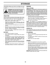
... of fuel gum deposits during storage. ENGINE FUEL SYSTEM IMPORTANT: IT IS IMPORTANT TO PREVENT GUM DEPOSITS FROM FORMING IN ESSENTIAL FUEL SYSTEM PARTS SUCH AS CARBURETOR, FUEL FILTER, FUEL HOSE, OR TANK DURING STORAGE. ALSO, EXPERIENCE INDICATES THAT ALCOHOL BLENDED FUELS (CALLED GASOHOL OR ...dirt in your gasoline will not be disconnected and battery cleaned thoroughly (see "TO CLEAN BATTERY AND TERMINALS" in the Maintenance section of this manual). • After cleaning, leave cables disconnected and place cables where they cannot come in contact with battery terminals. • If battery ...
... of fuel gum deposits during storage. ENGINE FUEL SYSTEM IMPORTANT: IT IS IMPORTANT TO PREVENT GUM DEPOSITS FROM FORMING IN ESSENTIAL FUEL SYSTEM PARTS SUCH AS CARBURETOR, FUEL FILTER, FUEL HOSE, OR TANK DURING STORAGE. ALSO, EXPERIENCE INDICATES THAT ALCOHOL BLENDED FUELS (CALLED GASOHOL OR ...dirt in your gasoline will not be disconnected and battery cleaned thoroughly (see "TO CLEAN BATTERY AND TERMINALS" in the Maintenance section of this manual). • After cleaning, leave cables disconnected and place cables where they cannot come in contact with battery terminals. • If battery ...

Owners Manual
Page 25
... Service and Adjustments section. Check tires for proper air pressure. 6. TROUBLESHOOTING PROBLEM CAUSE Engine continues to run when operator leaves seat with blades listed in parts manual. 11. Bent blade mandrel. 5. Replace blade mandrel. Engine speed too slow. 1. Faulty light switch. 4. Battery will not rotate 1. Replace alternator...
... Service and Adjustments section. Check tires for proper air pressure. 6. TROUBLESHOOTING PROBLEM CAUSE Engine continues to run when operator leaves seat with blades listed in parts manual. 11. Bent blade mandrel. 5. Replace blade mandrel. Engine speed too slow. 1. Faulty light switch. 4. Battery will not rotate 1. Replace alternator...

Owners Manual
Page 26
...Turf Saver LT" Tube Rear (Service Item Only) Rim Asm 8" Rear Sealant, Tire (10 oz. MODEL NUMBER YTH2042 (96043010601), PRODUCT NO. 960 43 01-06 DECALS 2 56 2 1 3 9 4 11 8 12 KEY PART NO. NO. 11 532 17 05-63 12 532 16 03-96 - - 532 16 69-60 - ...43 51-67 DESCRIPTION Decal, Warning Decal, Mower V-Belt Schematic Decal, Bypass Pad, Footrest, LH Pad, Footrest, RH Manual, Owner's (English) Manual, Owner's (French) WHEELS AND TIRES 1 2 11 3 4 7 10 6 wheel_art_1-tex 5 9 8 KEY PART NO. Tube) NOTE: All component dimensions given in U.S. TRACTOR - - NO. 1 532 41 16-58 2 532...
...Turf Saver LT" Tube Rear (Service Item Only) Rim Asm 8" Rear Sealant, Tire (10 oz. MODEL NUMBER YTH2042 (96043010601), PRODUCT NO. 960 43 01-06 DECALS 2 56 2 1 3 9 4 11 8 12 KEY PART NO. NO. 11 532 17 05-63 12 532 16 03-96 - - 532 16 69-60 - ...43 51-67 DESCRIPTION Decal, Warning Decal, Mower V-Belt Schematic Decal, Bypass Pad, Footrest, LH Pad, Footrest, RH Manual, Owner's (English) Manual, Owner's (French) WHEELS AND TIRES 1 2 11 3 4 7 10 6 wheel_art_1-tex 5 9 8 KEY PART NO. Tube) NOTE: All component dimensions given in U.S. TRACTOR - - NO. 1 532 41 16-58 2 532...

Owners Manual
Page 39
Keeper Belt Engine LH Keeper Belt Engine RH Keeper Belt Pulley Idler Spring Return Manual Clutch Cable Stud Fastener Nut Lock Hex Flange Bracket Brake Stand LH Screw 3/8-16 x 3/4 Screw TT #10-32 5 3/8 Flange Port Washout Coupling Quick connect Mandrel .... pulley/nut/washer and blade bolt/washers not included) Replacement Mower, Complete NOTE: All component dimensions given in U.S. MODEL NUMBER YTH2042 (96043010601), PRODUCT NO. 960 43 01-06 MOWER DECK KEY PART NO. NO. 56 532 19 90-92 57 817 00 06-16 59 532 14 10-43 60 532 19...
Keeper Belt Engine LH Keeper Belt Engine RH Keeper Belt Pulley Idler Spring Return Manual Clutch Cable Stud Fastener Nut Lock Hex Flange Bracket Brake Stand LH Screw 3/8-16 x 3/4 Screw TT #10-32 5 3/8 Flange Port Washout Coupling Quick connect Mandrel .... pulley/nut/washer and blade bolt/washers not included) Replacement Mower, Complete NOTE: All component dimensions given in U.S. MODEL NUMBER YTH2042 (96043010601), PRODUCT NO. 960 43 01-06 MOWER DECK KEY PART NO. NO. 56 532 19 90-92 57 817 00 06-16 59 532 14 10-43 60 532 19...


