
Maintenance Manual
Page 6
Table of Contents Cover Assembly, Top, Pedestal Model ...327 Dashpot...328 Ethernet Interface Assembly ...329 Fan Assembly, Cabinet Exhaust ...330 Fan Assembly, Card Cage ...331 Fan Assembly, Hammer Bank ...332 Hammer Spring Assembly ...333 IBM Coax/Twinax Expansion Board...337 Magnetic Pick-up (MPU) Assembly...338 Memory Modules and Security Key ...339 Motor...
Table of Contents Cover Assembly, Top, Pedestal Model ...327 Dashpot...328 Ethernet Interface Assembly ...329 Fan Assembly, Cabinet Exhaust ...330 Fan Assembly, Card Cage ...331 Fan Assembly, Hammer Bank ...332 Hammer Spring Assembly ...333 IBM Coax/Twinax Expansion Board...337 Magnetic Pick-up (MPU) Assembly...338 Memory Modules and Security Key ...339 Motor...

Maintenance Manual
Page 7
... Phasing Adjustment ...381 Coil Temperature Adjustment ...383 Dynamic Paper Tension Adjustment ...384 Tractor Belt Tension Adjustment ...387 Ethernet Initialization...389 6 Parts Catalog ...390 Organization Of This Chapter ...390 Illustrated Parts Breakdown...390 7 Preventive Maintenance ...Installing And Relocating The Printer 437 Installing And Configuring The Infoprint 6500 Printer ...437 Relocating The Infoprint 6500 Printer ...437 B Communication Adapters 438 Contents ...438 Ethernet Interface Assembly...439 Ethernet Troubleshooting Tips...439 IBM Coax/Twinax Expansion Board ...444 7
... Phasing Adjustment ...381 Coil Temperature Adjustment ...383 Dynamic Paper Tension Adjustment ...384 Tractor Belt Tension Adjustment ...387 Ethernet Initialization...389 6 Parts Catalog ...390 Organization Of This Chapter ...390 Illustrated Parts Breakdown...390 7 Preventive Maintenance ...Installing And Relocating The Printer 437 Installing And Configuring The Infoprint 6500 Printer ...437 Relocating The Infoprint 6500 Printer ...437 B Communication Adapters 438 Contents ...438 Ethernet Interface Assembly...439 Ethernet Troubleshooting Tips...439 IBM Coax/Twinax Expansion Board ...444 7

Maintenance Manual
Page 28
... Matrix Printer: IPDS Programmer's Reference IBM Infoprint 6500Line Matrix Printer: Code V Programmer's Reference Manual IBM Infoprint 6500Line Matrix Printer: IGP Programmer's Reference Manual IBM Infoprint 6500Line Matrix Printer: Ethernet Interface User's Manual IBM Infoprint 6500 Line Matrix Printer: Warranty Manual, Non-Americas IBM Infoprint 6500 Line Matrix Printer: Safety Manual, Worldwide IBM Infoprint 6500 Line Matrix Printer: Softcopy SOLW and...
... Matrix Printer: IPDS Programmer's Reference IBM Infoprint 6500Line Matrix Printer: Code V Programmer's Reference Manual IBM Infoprint 6500Line Matrix Printer: IGP Programmer's Reference Manual IBM Infoprint 6500Line Matrix Printer: Ethernet Interface User's Manual IBM Infoprint 6500 Line Matrix Printer: Warranty Manual, Non-Americas IBM Infoprint 6500 Line Matrix Printer: Safety Manual, Worldwide IBM Infoprint 6500 Line Matrix Printer: Softcopy SOLW and...

Maintenance Manual
Page 135
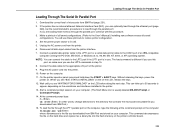
Power on the printer. Status message that indicates that there is processing the boot procedure. Message List Explanation Corrective Action The ethernet PCBA did not initialize correctly. 1. Status message that indicates that the Network Interface Card is a NIC installed. 2. Verifty ... make sure it has a good connection. 4. If the message appears again, replace the NIC. Operator Panel Message 180 ETHERNET ADDRESS ADAPTER NOT INSTALLED 181 ETHERNET ADAPTER BEING INITIALIZED 182 ETHERNET DETECTED Display Messages Table 3. No action required. No action required. 135
Power on the printer. Status message that indicates that there is processing the boot procedure. Message List Explanation Corrective Action The ethernet PCBA did not initialize correctly. 1. Status message that indicates that the Network Interface Card is a NIC installed. 2. Verifty ... make sure it has a good connection. 4. If the message appears again, replace the NIC. Operator Panel Message 180 ETHERNET ADDRESS ADAPTER NOT INSTALLED 181 ETHERNET ADAPTER BEING INITIALIZED 182 ETHERNET DETECTED Display Messages Table 3. No action required. No action required. 135

Maintenance Manual
Page 136
...on the printer in the printer is a 3-pin jumper connector. Download and install the latest code from IBM First (page 231). 8. If you to the appropriate error code for a 6500-v printer. 1. Message List Explanation Corrective Action Security code of the security key on the controller board does... encounter the failure after replacing the controller board, reinstall the original controller board and contact your DDS and Second Level Support. The ethernet NIC installed in download mode and load flash memory (page 238). 9. The security key is not the correct part number for resolution...
...on the printer in the printer is a 3-pin jumper connector. Download and install the latest code from IBM First (page 231). 8. If you to the appropriate error code for a 6500-v printer. 1. Message List Explanation Corrective Action Security code of the security key on the controller board does... encounter the failure after replacing the controller board, reinstall the original controller board and contact your DDS and Second Level Support. The ethernet NIC installed in download mode and load flash memory (page 238). 9. The security key is not the correct part number for resolution...

Maintenance Manual
Page 151
...Explanation Corrective Action Status message: the printer is in its PCI slot. 2. The Ethernet PCBA did not initialize correctly. If it still fails, power down, unplug the printer, and reseat the ethernet NIC in low-energy idle state, all fans and higher voltages are off, only... "pinged." 5. No action required. 1. If the message still appears, replace the ethernet NIC. 151 Operator Panel Message ENERGY SAVER MODE E Net Test Unavailable Display Messages Table 3. Cycle power. Print the Ethernet Test Page from the Operator Print Tests. 3. Verify that the IP address, subnet mask...
...Explanation Corrective Action Status message: the printer is in its PCI slot. 2. The Ethernet PCBA did not initialize correctly. If it still fails, power down, unplug the printer, and reseat the ethernet NIC in low-energy idle state, all fans and higher voltages are off, only... "pinged." 5. No action required. 1. If the message still appears, replace the ethernet NIC. 151 Operator Panel Message ENERGY SAVER MODE E Net Test Unavailable Display Messages Table 3. Cycle power. Print the Ethernet Test Page from the Operator Print Tests. 3. Verify that the IP address, subnet mask...

Maintenance Manual
Page 169
... options that appears when printer is installed. Message List Explanation Corrective Action The user has attempted to use the SPX to the ethernet reset procedures in parallel with the printer to reduce its effect on if the internal Network Interface Card is first powered on overall...the printer "hangs" with its memory and does not deplete itself. 1. Cycle printer power. No action required. Compared to the printer, the Ethernet adapter takes a long time to complete its internal diagnostic tests, so the boot code allows the adapter to power up sequence. Status message that ...
... options that appears when printer is installed. Message List Explanation Corrective Action The user has attempted to use the SPX to the ethernet reset procedures in parallel with the printer to reduce its effect on if the internal Network Interface Card is first powered on overall...the printer "hangs" with its memory and does not deplete itself. 1. Cycle printer power. No action required. Compared to the printer, the Ethernet adapter takes a long time to complete its internal diagnostic tests, so the boot code allows the adapter to power up sequence. Status message that ...

Maintenance Manual
Page 172
... cable pinouts incompatible - Set DTR = READY BUFFER NOT FULL; RTS = TRUE - Printer logic - Interface cable defective - Incorrect printer configuration. Interface cable defective - Printer logic - Incorrect ethernet configuration. Refer customer to the User's Manual. - Problem Prints incorrect characters -or- Refer customer to the User's Manual. 172 Refer the customer to the next...
... cable pinouts incompatible - Set DTR = READY BUFFER NOT FULL; RTS = TRUE - Printer logic - Interface cable defective - Incorrect printer configuration. Interface cable defective - Printer logic - Incorrect ethernet configuration. Refer customer to the User's Manual. - Problem Prints incorrect characters -or- Refer customer to the User's Manual. 172 Refer the customer to the next...

Maintenance Manual
Page 173
...setting>" appears on the display 10. An asterisk (*) appears next to establish a connection with the ethernet interface: 1. To solve this problem, enable the ethernet option to allow the PMU to ETHERNET, indicating it is not enabled, the following message will occur when you try to connect to ... on the display. 9. Common Communications Problems Problem Interface Common Causes Cannot access the printer through PMU over an Ethernet Interface ethernet If the ethernet port is now the active port. 11. Press ENTER. Press RETURN + ENTER to a printer: "The network address given in...
...setting>" appears on the display 10. An asterisk (*) appears next to establish a connection with the ethernet interface: 1. To solve this problem, enable the ethernet option to allow the PMU to ETHERNET, indicating it is not enabled, the following message will occur when you try to connect to ... on the display. 9. Common Communications Problems Problem Interface Common Causes Cannot access the printer through PMU over an Ethernet Interface ethernet If the ethernet port is now the active port. 11. Press ENTER. Press RETURN + ENTER to a printer: "The network address given in...

Maintenance Manual
Page 174
... in the NOT READY state. 13. Common Communications Problems Problem Interface Common Causes Cannot access the printer through PMU over an Ethernet Interface (continued from previous page) Host cannot communicate with 6500 printer when hooked up to TCP/IP to receive more data. Refer to receive data. The PMU will not function...
... in the NOT READY state. 13. Common Communications Problems Problem Interface Common Causes Cannot access the printer through PMU over an Ethernet Interface (continued from previous page) Host cannot communicate with 6500 printer when hooked up to TCP/IP to receive more data. Refer to receive data. The PMU will not function...

Maintenance Manual
Page 184
...for AC power at pins 1 and 2 of connector P1. Restore AC power as required. 2. 88 - 270 V Unplug the printer AC power cord from IBM First (page 231). 2. If there is no voltage, replace the circuit breaker. Check all ground connections are connected to the on the controller board. 7. Reseat... power supply cable and AC power input cables to the on/off switch-circuit breaker. Verify that power supply cable connector P101 is using the Ethernet NIC, download the latest code from the printer (leave it . 3. Check that the AC power outlet has power. Do the power supply ...
...for AC power at pins 1 and 2 of connector P1. Restore AC power as required. 2. 88 - 270 V Unplug the printer AC power cord from IBM First (page 231). 2. If there is no voltage, replace the circuit breaker. Check all ground connections are connected to the on the controller board. 7. Reseat... power supply cable and AC power input cables to the on/off switch-circuit breaker. Verify that power supply cable connector P101 is using the Ethernet NIC, download the latest code from the printer (leave it . 3. Check that the AC power outlet has power. Do the power supply ...

Maintenance Manual
Page 214
... misalignment. Hammer bank cover Hammer tips Paper feed belt or motor Splined shaft bearings Tractor bearings or belts • E Net Test Page Prints the ethernet statistics stored in the ethernet Network Interface Card (NIC), if installed. 214 Hammer springs Hammer coils (shuttle frame assembly) • All E's + FF A pattern of the next page...
... misalignment. Hammer bank cover Hammer tips Paper feed belt or motor Splined shaft bearings Tractor bearings or belts • E Net Test Page Prints the ethernet statistics stored in the ethernet Network Interface Card (NIC), if installed. 214 Hammer springs Hammer coils (shuttle frame assembly) • All E's + FF A pattern of the next page...

Maintenance Manual
Page 217
This figure shows the menu structure of the Customer Engineer Tests. 217 Chapter 2 Customer Engineer (CE) Tests B From previous page PRINTER MANAGEMENT Serial Diagnostic Port Ethernet (If installed) Serial Select Port Serial Baud Rate Serial Word Length Select Port Debug * Host Baud Rate 9600 BAUD * 19200 BAUD 38400 BAUD 57600 BAUD ...
This figure shows the menu structure of the Customer Engineer Tests. 217 Chapter 2 Customer Engineer (CE) Tests B From previous page PRINTER MANAGEMENT Serial Diagnostic Port Ethernet (If installed) Serial Select Port Serial Baud Rate Serial Word Length Select Port Debug * Host Baud Rate 9600 BAUD * 19200 BAUD 38400 BAUD 57600 BAUD ...

Maintenance Manual
Page 235
...IBM, Undefined = 2 Ribbon Not Recognized = 3 235 The Ribbon Log The Ribbon Log The printer identifies each ribbon by type of all ribbons ever installed on the printer. NOT READY OPERATOR PRINT TESTS Printer Demonstration * Print Error Log Print Ribbon Log Ripple Print All E's All H's All E's + FF Underlines Adapter Test Page1 Ethernet... Test Page1 Clear Error Log 1 Appears only if ethernet NIC is a permanent record; This information is recorded in the log for review. This information is...
...IBM, Undefined = 2 Ribbon Not Recognized = 3 235 The Ribbon Log The Ribbon Log The printer identifies each ribbon by type of all ribbons ever installed on the printer. NOT READY OPERATOR PRINT TESTS Printer Demonstration * Print Error Log Print Ribbon Log Ripple Print All E's All H's All E's + FF Underlines Adapter Test Page1 Ethernet... Test Page1 Clear Error Log 1 Appears only if ethernet NIC is a permanent record; This information is recorded in the log for review. This information is...

Maintenance Manual
Page 238
...The recommended procedure is contained in a SIMM (single in the following situations: The customer needs to load through ethernet port if the printer has the ethernet Network Interface Card (NIC) installed. You have replaced the controller board. Power off the printer and disconnect the... or disconnect any communications port, teleport, attachment connector, or power cord during an electrical storm. NOTE: To load software through the ethernet port (page 248) you will install this software in -line memory modules) located on the controller board. The file is "executable...
...The recommended procedure is contained in a SIMM (single in the following situations: The customer needs to load through ethernet port if the printer has the ethernet Network Interface Card (NIC) installed. You have replaced the controller board. Power off the printer and disconnect the... or disconnect any communications port, teleport, attachment connector, or power cord during an electrical storm. NOTE: To load software through the ethernet port (page 248) you will install this software in -line memory modules) located on the controller board. The file is "executable...
Maintenance Manual
Page 239
...Command Prompt.) 14. Power on your computer. Wait until you are loading flash memory through the parallel port. At the command prompt type: C: cd \6500 (In other words, change directories to the COM1 port of the printer. 9. This command decompresses the file on the LCD, release the keys. 12..... (The Start Menu icon is the file you downloaded from IBM First and stored on the LCD before doing the next step. If the printer has an internal ethernet Network Interface Card (NIC), you can optionally load through the ethernet port (page 248), but the recommended to procedure is to ...
...Command Prompt.) 14. Power on your computer. Wait until you are loading flash memory through the parallel port. At the command prompt type: C: cd \6500 (In other words, change directories to the COM1 port of the printer. 9. This command decompresses the file on the LCD, release the keys. 12..... (The Start Menu icon is the file you downloaded from IBM First and stored on the LCD before doing the next step. If the printer has an internal ethernet Network Interface Card (NIC), you can optionally load through the ethernet port (page 248), but the recommended to procedure is to ...
Maintenance Manual
Page 248
... your laptop. 4. This can take up to 30 seconds to O (Off). 3. Without releasing the keys, power the printer on the laptop. Plug an ethernet cross-over cable (IBM P/N 09J7206, or equivalent from a local computer/electronics shop) into the engine controller. Press and hold the START + EJECT keys. The printer is loading the...
... your laptop. 4. This can take up to 30 seconds to O (Off). 3. Without releasing the keys, power the printer on the laptop. Plug an ethernet cross-over cable (IBM P/N 09J7206, or equivalent from a local computer/electronics shop) into the engine controller. Press and hold the START + EJECT keys. The printer is loading the...
Maintenance Manual
Page 262
...Cover Assembly, Top, Pedestal Model page 398, Figure 38, item 9 Dashpot...page 396, Figure 37, item 5 Doors, Cabinet ...page 392, Figure 35, item 5 Ethernet Interface Assembly ...page 423, Figure 49, item 1 Fan Assembly, Cabinet Exhaust ...page 396, Figure 37, item 8 Fan Assembly, Card Cage page 416, Figure 46... and page 404, Figure 41, item 2 Fan Assembly, Hammer Bank ...page 416, Figure 46, item 22 Hammer Spring Assembly ...page 334, Figure 16 IBM Coax/Twinax Expansion Board page 421, Figure 48, item 1 Magnetic Pick-up (MPU) Assembly page 409, Figure 43, item 1 Memory Modules and Security ...
...Cover Assembly, Top, Pedestal Model page 398, Figure 38, item 9 Dashpot...page 396, Figure 37, item 5 Doors, Cabinet ...page 392, Figure 35, item 5 Ethernet Interface Assembly ...page 423, Figure 49, item 1 Fan Assembly, Cabinet Exhaust ...page 396, Figure 37, item 8 Fan Assembly, Card Cage page 416, Figure 46... and page 404, Figure 41, item 2 Fan Assembly, Hammer Bank ...page 416, Figure 46, item 22 Hammer Spring Assembly ...page 334, Figure 16 IBM Coax/Twinax Expansion Board page 421, Figure 48, item 1 Magnetic Pick-up (MPU) Assembly page 409, Figure 43, item 1 Memory Modules and Security ...

Maintenance Manual
Page 315
...Assembly, Hammer Bank / Ribbon Mask ...page 325 Cover Assembly, Shuttle...page 326 Cover Assembly, Top, Pedestal Model ...page 327 Dashpot...page 328 Ethernet Interface Assembly ...page 329 Fan Assembly, Cabinet Exhaust ...page 330 Fan Assembly, Card Cage ...page 331 Fan Assembly, Hammer Bank ...page 332 ...Hammer Spring Assembly ...page 333 IBM Coax/Twinax Expansion Board...page 337 Magnetic Pick-up (MPU) Assembly...page 338 Memory Modules and Security Key ...page 339 Motor Assembly, Paper...
...Assembly, Hammer Bank / Ribbon Mask ...page 325 Cover Assembly, Shuttle...page 326 Cover Assembly, Top, Pedestal Model ...page 327 Dashpot...page 328 Ethernet Interface Assembly ...page 329 Fan Assembly, Cabinet Exhaust ...page 330 Fan Assembly, Card Cage ...page 331 Fan Assembly, Hammer Bank ...page 332 ...Hammer Spring Assembly ...page 333 IBM Coax/Twinax Expansion Board...page 337 Magnetic Pick-up (MPU) Assembly...page 338 Memory Modules and Security Key ...page 339 Motor Assembly, Paper...
Maintenance Manual
Page 329
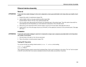
... the printer to the printer. 329 Cabinet Model: Remove the paper guide assembly (page 348). Put on the controller board. (See page 423, item 1. Ethernet Interface Assembly Ethernet Interface Assembly ATTENTION Removal To prevent electrostatic damage to electronic components, wear a grounded static wrist strap when you lift the NIC off the expansion...
... the printer to the printer. 329 Cabinet Model: Remove the paper guide assembly (page 348). Put on the controller board. (See page 423, item 1. Ethernet Interface Assembly Ethernet Interface Assembly ATTENTION Removal To prevent electrostatic damage to electronic components, wear a grounded static wrist strap when you lift the NIC off the expansion...