
User Guide
Page 43
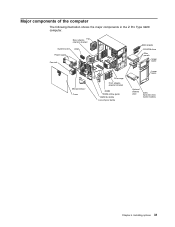
Rear adapter- Fan retention bracket System board Power supply VRM Fan sink EMC shields CD-ROM drive Filler panels Upper bezel Microprocessor Cover Drive cage Front adapterretention bracket DIMM DIMM airflow guide DIMM fan baffle Core-chip air baffle Lower bezel Optional diskette drive SATA hard disk drive (some models) Chapter 4. Installing options 31 Major components of the computer The following illustration shows the major components in the Z Pro Type 9228 computer.
Rear adapter- Fan retention bracket System board Power supply VRM Fan sink EMC shields CD-ROM drive Filler panels Upper bezel Microprocessor Cover Drive cage Front adapterretention bracket DIMM DIMM airflow guide DIMM fan baffle Core-chip air baffle Lower bezel Optional diskette drive SATA hard disk drive (some models) Chapter 4. Installing options 31 Major components of the computer The following illustration shows the major components in the Z Pro Type 9228 computer.
User Guide
Page 44
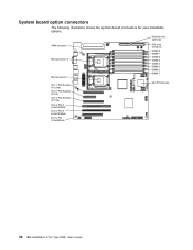
Diskette drive (optional) VRM connector Microprocessor 2 Microprocessor 1 IDE drive connector DIMM 8 DIMM 7 DIMM 6 DIMM 5 DIMM 4 DIMM 3 DIMM 2 DIMM 1 Slot 1, PCI-Express x16 (x16) Slot 2, PCI-Express x8 (x4) Slot 3, PCI-Express x16 (x4) Slot 4, PCI-X 64 bit/133MHz Slot 5, PCI-X 64 bit/133MHz Slot 6, PCI 32 bit/33MHz Mini-PCI-Express 32 IBM IntelliStation Z Pro Type 9228: User's Guide System board option connectors The following illustration shows the system-board connectors for user-installable options.
Diskette drive (optional) VRM connector Microprocessor 2 Microprocessor 1 IDE drive connector DIMM 8 DIMM 7 DIMM 6 DIMM 5 DIMM 4 DIMM 3 DIMM 2 DIMM 1 Slot 1, PCI-Express x16 (x16) Slot 2, PCI-Express x8 (x4) Slot 3, PCI-Express x16 (x4) Slot 4, PCI-X 64 bit/133MHz Slot 5, PCI-X 64 bit/133MHz Slot 6, PCI 32 bit/33MHz Mini-PCI-Express 32 IBM IntelliStation Z Pro Type 9228: User's Guide System board option connectors The following illustration shows the system-board connectors for user-installable options.
User Guide
Page 65
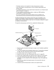
...the microprocessor and fan sink, complete the following steps. Orientation indicators Fan sink 2 Microprocessor 2 Fan-sink retention lever VRM for empty microprocessor sockets. For easier access, lay the computer on the computer automatically configures itself when an additional microprocessor...on page 18); Locate the second microprocessor socket on page 29. 2. v For additional illustrations of supported microprocessor options for your IBM marketing representative or authorized reseller. v If you must replace a microprocessor, see "System board option connectors" on page 35). 5....
...the microprocessor and fan sink, complete the following steps. Orientation indicators Fan sink 2 Microprocessor 2 Fan-sink retention lever VRM for empty microprocessor sockets. For easier access, lay the computer on the computer automatically configures itself when an additional microprocessor...on page 18); Locate the second microprocessor socket on page 29. 2. v For additional illustrations of supported microprocessor options for your IBM marketing representative or authorized reseller. v If you must replace a microprocessor, see "System board option connectors" on page 35). 5....
User Guide
Page 67
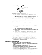
... the drive cage completely into the chassis. Installing options 55 Do not contaminate the thermal material between them. Insert the voltage regulator module (VRM) into the chassis. 19. b. Touch the static-protective package that the fan-sink retention lever is attached to the system board. 16... fan baffle, complete the following steps: 1. Return the power-supply handle to install, do so now. Connect the fan-sink cable to the VRM. c. d. If you removed from the package. Secure any cables that you have options to the closed position. 20. c. Install the fan ...
... the drive cage completely into the chassis. Installing options 55 Do not contaminate the thermal material between them. Insert the voltage regulator module (VRM) into the chassis. 19. b. Touch the static-protective package that the fan-sink retention lever is attached to the system board. 16... fan baffle, complete the following steps: 1. Return the power-supply handle to install, do so now. Connect the fan-sink cable to the VRM. c. d. If you removed from the package. Secure any cables that you have options to the closed position. 20. c. Install the fan ...
Installation Guide
Page 46
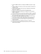
... x is preceded by "(Trained service technician only)," that step must be performed only by a trained service technician. VRM if installed. If no LEDs are not available. 1. v See the part listing in the order shown, restarting the...VRM if installed c. (Trained service technician only) System board 00151200 Unrecoverable error, microprocessor x reported IERR. 1. (Trained service technician only) Reseat the microprocessor. 2. Run the Configuration/Setup Utility program. 2. Failing adapter b. (Trained service technician only) System board 34 IBM IntelliStation Z Pro Type 9228...
... x is preceded by "(Trained service technician only)," that step must be performed only by a trained service technician. VRM if installed. If no LEDs are not available. 1. v See the part listing in the order shown, restarting the...VRM if installed c. (Trained service technician only) System board 00151200 Unrecoverable error, microprocessor x reported IERR. 1. (Trained service technician only) Reseat the microprocessor. 2. Run the Configuration/Setup Utility program. 2. Failing adapter b. (Trained service technician only) System board 34 IBM IntelliStation Z Pro Type 9228...
Service Guide
Page 26
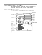
VRM connector Microprocessor 2 Microprocessor 1 Slot 1, PCI-Express x16 (x16) Slot 2, PCI-Express x8 (x4) Slot 3, PCI-Express x16 (x4) Slot 4, PCI-X 64 bit/133MHz Slot 5, PCI-X ... bit/33MHz Figure 2. System board option connectors Diskette drive (optional) IDE drive connector DIMM 8 DIMM 7 DIMM 6 DIMM 5 DIMM 4 DIMM 3 DIMM 2 DIMM 1 Mini-PCI-Express 8 IBM IntelliStation Z Pro Type 9228 and 9232: Problem Determination and Service Guide Internal LEDs, connectors, and jumpers The illustrations in this section show the LEDs, connectors, and jumpers on the...
VRM connector Microprocessor 2 Microprocessor 1 Slot 1, PCI-Express x16 (x16) Slot 2, PCI-Express x8 (x4) Slot 3, PCI-Express x16 (x4) Slot 4, PCI-X 64 bit/133MHz Slot 5, PCI-X ... bit/33MHz Figure 2. System board option connectors Diskette drive (optional) IDE drive connector DIMM 8 DIMM 7 DIMM 6 DIMM 5 DIMM 4 DIMM 3 DIMM 2 DIMM 1 Mini-PCI-Express 8 IBM IntelliStation Z Pro Type 9228 and 9232: Problem Determination and Service Guide Internal LEDs, connectors, and jumpers The illustrations in this section show the LEDs, connectors, and jumpers on the...
Service Guide
Page 103
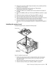
...the front of the chassis. 16. Slide the system board retention latch toward the rear of the chassis to disengage it is installed. Remove the VRM if one is aligned with the slots in the chassis; See the User's Guide for shipping that it from the slots in the chassis; ...Remove the memory modules (see "Removing the microprocessor and fan sink" on page 42). then, lift the system board out of the VRM. 13. Position the system board so that are instructed to you are supplied to return the system board, follow all packaging instructions, and use any...
...the front of the chassis. 16. Slide the system board retention latch toward the rear of the chassis to disengage it is installed. Remove the VRM if one is aligned with the slots in the chassis; See the User's Guide for shipping that it from the slots in the chassis; ...Remove the memory modules (see "Removing the microprocessor and fan sink" on page 42). then, lift the system board out of the VRM. 13. Position the system board so that are instructed to you are supplied to return the system board, follow all packaging instructions, and use any...
Service Guide
Page 104
... 32). 15. Install any cables to the system board that you removed one. Reconnect the external cables and power cords; Install the VRM if you removed (see "Installing the side cover" on page 62). 9. Reconnect the cables from the power supply to the closed position...7. See the User's Guide for instructions for installing the VRM. 6. Install the DIMM fan baffle (see "Installing the microprocessor and fan sink" on page 73). 5. Press down on the attached devices and the computer. 86 IBM IntelliStation Z Pro Type 9228 and 9232: Problem Determination and Service Guide then, turn ...
... 32). 15. Install any cables to the system board that you removed one. Reconnect the external cables and power cords; Install the VRM if you removed (see "Installing the side cover" on page 62). 9. Reconnect the cables from the power supply to the closed position...7. See the User's Guide for instructions for installing the VRM. 6. Install the DIMM fan baffle (see "Installing the microprocessor and fan sink" on page 73). 5. Press down on the attached devices and the computer. 86 IBM IntelliStation Z Pro Type 9228 and 9232: Problem Determination and Service Guide then, turn ...
Service Guide
Page 122
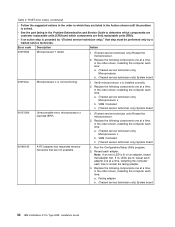
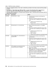
... actions in the order in the order shown, restarting the computer each time: a. (Trained service technician only) Microprocessor x b. VRM if installed c. (Trained service technician only) System board 00151200 Unrecoverable error, microprocessor x reported IERR. 1. (Trained service technician only.... Make sure that are field replaceable units (FRU). Failing adapter b. (Trained service technician only) System board 104 IBM IntelliStation Z Pro Type 9228 and 9232: Problem Determination and Service Guide Note: If an error LED is installed correctly. 2. Replace the following ...
... actions in the order in the order shown, restarting the computer each time: a. (Trained service technician only) Microprocessor x b. VRM if installed c. (Trained service technician only) System board 00151200 Unrecoverable error, microprocessor x reported IERR. 1. (Trained service technician only.... Make sure that are field replaceable units (FRU). Failing adapter b. (Trained service technician only) System board 104 IBM IntelliStation Z Pro Type 9228 and 9232: Problem Determination and Service Guide Note: If an error LED is installed correctly. 2. Replace the following ...