Hard Drive Specifications
Page 5
... Fixed disk subsystem description 9 3.1 Control Electronics 9 3.2 Head disk assembly data 9 4.0 Fixed disk characteristics 11 4.1 Default logical drive parameters 11 4.2 Formatted capacity by model number 11 4.3 Data sheet 12 4.4 Cylinder allocation by model number 12 4.5 Performance characteristics ... 26 6.4 Reliability 28 6.4.1 Data reliability 28 6.4.2 Failure prediction (S.M.A.R.T 28 6.4.3 Cable noise interference 28 6.4.4 Service life and usage condition 29 6.4.5 Preventive maintenance 29 6.4.6 Load/unload 29 Travelstar 32GH/30GT/20GN hard disk drive specifications v
... Fixed disk subsystem description 9 3.1 Control Electronics 9 3.2 Head disk assembly data 9 4.0 Fixed disk characteristics 11 4.1 Default logical drive parameters 11 4.2 Formatted capacity by model number 11 4.3 Data sheet 12 4.4 Cylinder allocation by model number 12 4.5 Performance characteristics ... 26 6.4 Reliability 28 6.4.1 Data reliability 28 6.4.2 Failure prediction (S.M.A.R.T 28 6.4.3 Cable noise interference 28 6.4.4 Service life and usage condition 29 6.4.5 Preventive maintenance 29 6.4.6 Load/unload 29 Travelstar 32GH/30GT/20GN hard disk drive specifications v

Hard Drive Specifications
Page 6
...59 8.0 General 61 8.1 Introduction 61 8.2 Terminology 61 9.0 Deviations from standard 63 10.0 Registers 65 10.1 Alternate Status Register 66 Travelstar 32GH/30GT/20GN hard disk drive specifications vi 6.5 Mechanical specifications 31 6.5.1 Physical dimensions and weight 31 6.5.2 Mounting ...38 6.9.2 C-Tick Mark 38 6.10 Safety 39 6.10.1 UL and CSA approval 39 6.10.2 IEC compliance 39 6.10.3 German Safety Mark 39 6.10.4 Flammability 39 6.10.5 Secondary circuit protection 39 6.11 Packaging 39 7.0 Electrical interface specifications 41 7.1 Cabling 41 7.2 Interface connector 41 7.3...
...59 8.0 General 61 8.1 Introduction 61 8.2 Terminology 61 9.0 Deviations from standard 63 10.0 Registers 65 10.1 Alternate Status Register 66 Travelstar 32GH/30GT/20GN hard disk drive specifications vi 6.5 Mechanical specifications 31 6.5.1 Physical dimensions and weight 31 6.5.2 Mounting ...38 6.9.2 C-Tick Mark 38 6.10 Safety 39 6.10.1 UL and CSA approval 39 6.10.2 IEC compliance 39 6.10.3 German Safety Mark 39 6.10.4 Flammability 39 6.10.5 Secondary circuit protection 39 6.11 Packaging 39 7.0 Electrical interface specifications 41 7.1 Cabling 41 7.2 Interface connector 41 7.3...
Hard Drive Specifications
Page 42
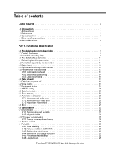
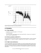
... common mode noise or voltage level difference between the system frame and power cable ground or AT interface cable ground should be grounded electrically to 15 symbols of DJSA-232 6.4 Reliability 6.4.1 Data reliability ! Typical current wave form at start up to the system frame by four screws. Travelstar 32GH/30GT/20GN hard disk drive specifications 28
... common mode noise or voltage level difference between the system frame and power cable ground or AT interface cable ground should be grounded electrically to 15 symbols of DJSA-232 6.4 Reliability 6.4.1 Data reliability ! Typical current wave form at start up to the system frame by four screws. Travelstar 32GH/30GT/20GN hard disk drive specifications 28

Hard Drive Specifications
Page 55
...setting. (Refer to mate with the 50 pin plug specified in Annex A, Connectors and Cable Assembly, of the ATA/ATAPI-5 document. Interface connector pin assignments Travelstar 32GH/30GT/20GN hard disk drive specifications 41 Pin 43 19 1 CA 44 22 2 DB Pin Note 1: Pin position...below and Figure 6.5.2 on page 57 for correct address setting.) Figure 32. 7.0 Electrical interface specifications 7.1 Cabling The maximum cable length from the host system to the hard disk drive shall not exceed 18 inches. 7.2 Interface connector The signal connector for AT attachment is left blank for ...
...setting. (Refer to mate with the 50 pin plug specified in Annex A, Connectors and Cable Assembly, of the ATA/ATAPI-5 document. Interface connector pin assignments Travelstar 32GH/30GT/20GN hard disk drive specifications 41 Pin 43 19 1 CA 44 22 2 DB Pin Note 1: Pin position...below and Figure 6.5.2 on page 57 for correct address setting.) Figure 32. 7.0 Electrical interface specifications 7.1 Cabling The maximum cable length from the host system to the hard disk drive shall not exceed 18 inches. 7.2 Interface connector The signal connector for AT attachment is left blank for ...

Hard Drive Specifications
Page 58
... drive is driven by device 1. Travelstar 32GH/30GT/20GN hard disk drive specifications 44 If -DASP was not asserted by Device 1 within 1 ms to indicate to one HDD should clear BSY before asserting -PDIAG, as a Slave. KEY Pin position 20 has no longer busy and is able to close the respective position of the cable... status immediately after it is recommended to provide status. The -DASP signal shall be connected to the host IORDY signal in order to 5 volts through a 10 kΩ resistor. If CSEL is open or is present.
... drive is driven by device 1. Travelstar 32GH/30GT/20GN hard disk drive specifications 44 If -DASP was not asserted by Device 1 within 1 ms to indicate to one HDD should clear BSY before asserting -PDIAG, as a Slave. KEY Pin position 20 has no longer busy and is able to close the respective position of the cable... status immediately after it is recommended to provide status. The -DASP signal shall be connected to the host IORDY signal in order to 5 volts through a 10 kΩ resistor. If CSEL is open or is present.

Hard Drive Specifications
Page 71
...setting The default setting of jumper at shipment is grounded the drive does not spin up at the interface connector to determine the drive address. Travelstar 32GH/30GT/20GN hard disk drive specifications 57 Using Cable Selection, the drive address depends on the condition of pin 28 of the jumper... is a Master. The set position of the AT interface cable. In the case when pin 28 is ground, or low, the drive is as shown below. 7.10 Drive...
...setting The default setting of jumper at shipment is grounded the drive does not spin up at the interface connector to determine the drive address. Travelstar 32GH/30GT/20GN hard disk drive specifications 57 Using Cable Selection, the drive address depends on the condition of pin 28 of the jumper... is a Master. The set position of the AT interface cable. In the case when pin 28 is ground, or low, the drive is as shown below. 7.10 Drive...