
User Guide
Page 5
... help xx How to the switch 15 Creating a serial connection 16 Setting the switch IP address 16 Setting the date and time 17 © Copyright IBM Corp. 2008 iii Introducing the SAN40B-4 switch 1 Features and functions of the switch 1 Supported connectivity 2 Port side of the switch 2 Port numbering 3 Nonport side of the switch 4 Field replaceable units (FRUs 4 Additional...
... help xx How to the switch 15 Creating a serial connection 16 Setting the switch IP address 16 Setting the date and time 17 © Copyright IBM Corp. 2008 iii Introducing the SAN40B-4 switch 1 Features and functions of the switch 1 Supported connectivity 2 Port side of the switch 2 Port numbering 3 Nonport side of the switch 4 Field replaceable units (FRUs 4 Additional...

User Guide
Page 6
... Data transmission ranges 37 Fibre Channel port specifications 38 Serial port specifications 38 Power supply specifications 38 Supported SFPs and HBAs 39 System specifications 39 Notices 41 Trademarks 43 Electronic emission notices 44 Federal Communications Commission (FCC) Class A Statement . . . . ...Class A ITE Electronic Emission Statement 46 Korea Class A Electronic Emission Statement 46 Index 47 iv SAN40B-4 Installation, Service, and User's Guide Operating the switch 21 Powering the switch on and off 21 Interpreting LED activity 21 LED locations 22 LED patterns 23 POST and ...
... Data transmission ranges 37 Fibre Channel port specifications 38 Serial port specifications 38 Power supply specifications 38 Supported SFPs and HBAs 39 System specifications 39 Notices 41 Trademarks 43 Electronic emission notices 44 Federal Communications Commission (FCC) Class A Statement . . . . ...Class A ITE Electronic Emission Statement 46 Korea Class A Electronic Emission Statement 46 Index 47 iv SAN40B-4 Installation, Service, and User's Guide Operating the switch 21 Powering the switch on and off 21 Interpreting LED activity 21 LED locations 22 LED patterns 23 POST and ...
User Guide
Page 7
Mounting the moving portion of the rail and the locking brackets to the switch 12 7. Detailed view, location of LEDs on the port side of the switch 4 4. Captive screws on the nonport side of the switch 2 2. Non-port side of the switch 22 10. SFP installation and bail closing 27 12. Removing an SFP ... 32 14. Separating the inner and outer rails 11 6. Rack assembly 10 5. Inserting slides into the rack rails 14 9. Figures 1. Port side of the switch 22 11. Fibre Channel port numbering 3 3. Installing a replacement power supply fan assembly 33 © Copyright...
Mounting the moving portion of the rail and the locking brackets to the switch 12 7. Detailed view, location of LEDs on the port side of the switch 4 4. Captive screws on the nonport side of the switch 2 2. Non-port side of the switch 22 10. SFP installation and bail closing 27 12. Removing an SFP ... 32 14. Separating the inner and outer rails 11 6. Rack assembly 10 5. Inserting slides into the rack rails 14 9. Figures 1. Port side of the switch 22 11. Fibre Channel port numbering 3 3. Installing a replacement power supply fan assembly 33 © Copyright...
User Guide
Page 9
Data transmission ranges 37 15. Brocade and IBM product and model number matrix xx 3. System status LED patterns, status, and recommended actions 23 6. Power supply status LED patterns, status, and recommended actions 25 9. Switch power supply specifications 38 17. Tables 1. Memory specifications 37 14. Environmental requirements 36 13. Power status LED patterns, status, and...
Data transmission ranges 37 15. Brocade and IBM product and model number matrix xx 3. System status LED patterns, status, and recommended actions 23 6. Power supply status LED patterns, status, and recommended actions 25 9. Switch power supply specifications 38 17. Tables 1. Memory specifications 37 14. Environmental requirements 36 13. Power status LED patterns, status, and...

User Guide
Page 21
... documents contain information related to this product: v IBM System Storage SAN40B-4 Installation, Service, and User's Guide, GA32-0581 (this document) v IBM System Storage SAN40B-4 Quick Start Guide, GA32-0586 v IBM Systems Safety Notices, G229-9054 v IBM System Storage SAN 2498 Statement of Limited Warranty, GA32-0584 Brocade documents IBM b-type switches use software licensed from Brocade Communications Systems, Inc. This document has been created to include...
... documents contain information related to this product: v IBM System Storage SAN40B-4 Installation, Service, and User's Guide, GA32-0581 (this document) v IBM System Storage SAN40B-4 Quick Start Guide, GA32-0586 v IBM Systems Safety Notices, G229-9054 v IBM System Storage SAN 2498 Statement of Limited Warranty, GA32-0584 Brocade documents IBM b-type switches use software licensed from Brocade Communications Systems, Inc. This document has been created to include...

User Guide
Page 25
... a 667 MHz PowerPC® 440EPx Reduced Instruction Set Computer (RISC) CPU with IBM System Storage SAN switch models, 1, 2, 4, and 8 Gbps auto-sensing capability, as well as E, F, M, or FL ports, and EX_Ports. Chapter 1. Introducing the SAN40B-4 switch The IBM System Storage SAN40B-4 is an enterprise-class 8 Gbps Fibre Channel switch that is designed to handle the large-scale SAN requirements of an...
... a 667 MHz PowerPC® 440EPx Reduced Instruction Set Computer (RISC) CPU with IBM System Storage SAN switch models, 1, 2, 4, and 8 Gbps auto-sensing capability, as well as E, F, M, or FL ports, and EX_Ports. Chapter 1. Introducing the SAN40B-4 switch The IBM System Storage SAN40B-4 is an enterprise-class 8 Gbps Fibre Channel switch that is designed to handle the large-scale SAN requirements of an...
User Guide
Page 26
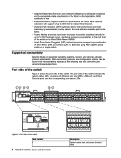
...World Wide Name (WWN). Hardware zoning is accomplished at the following web site: www.ibm.com/ servers/storage/support/san. Port side of the switch Figure 1 shows the port side of the switch or by automatically routing data to the most efficient available path in the interoperability matrices... at the port level of the switch. The port side of the switch Item number 1 2 SAN40B-4 Installation, Service, and User's Guide 8 9 10 11 12 13 14 15 Description System status (top) and power (bottom) LEDs Port side of the switch includes the system status LED, console port, Ethernet port...
...World Wide Name (WWN). Hardware zoning is accomplished at the following web site: www.ibm.com/ servers/storage/support/san. Port side of the switch Figure 1 shows the port side of the switch or by automatically routing data to the most efficient available path in the interoperability matrices... at the port level of the switch. The port side of the switch Item number 1 2 SAN40B-4 Installation, Service, and User's Guide 8 9 10 11 12 13 14 15 Description System status (top) and power (bottom) LEDs Port side of the switch includes the system status LED, console port, Ethernet port...
User Guide
Page 27
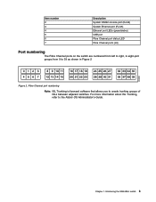
Introducing the SAN40B-4 switch 3 Chapter 1. Item number 2 3 4 5 6 7 Description System RS232 console port (RJ-45) System Ethernet port (RJ-45) Ethernet port LEDs (green/amber) USB port Fibre Channel port status LED Fibre Channel ports (40) Port numbering The Fibre Channel ports on the switch are numbered from 0 to the Fabric OS Administrator's Guide. For more information... 38 39 b40_0002 Figure 2. Fibre Channel port numbering Note: ISL Trunking is licensed software that allows you to create trunking groups of ISLs between adjacent switches.
Introducing the SAN40B-4 switch 3 Chapter 1. Item number 2 3 4 5 6 7 Description System RS232 console port (RJ-45) System Ethernet port (RJ-45) Ethernet port LEDs (green/amber) USB port Fibre Channel port status LED Fibre Channel ports (40) Port numbering The Fibre Channel ports on the switch are numbered from 0 to the Fabric OS Administrator's Guide. For more information... 38 39 b40_0002 Figure 2. Fibre Channel port numbering Note: ISL Trunking is licensed software that allows you to create trunking groups of ISLs between adjacent switches.
User Guide
Page 28
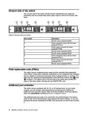
...status LED ( 2 and 6 in the switch firmware. After it . 4 SAN40B-4 Installation, Service, and User's Guide Non-port side of the entire switch, including the two FAN/PS FRU units. The FRU units are capable of functioning universally without voltage jumpers or switches. The additional ports are ready to unlock... with 24, 32, or 40 licensed ports. Nonport side of the switch The non-port side of the licensed paper pack supplied with switch software, or you can purchase the license separately from IBM, who will provide you can activate unlicensed ports by purchasing and installing the...
...status LED ( 2 and 6 in the switch firmware. After it . 4 SAN40B-4 Installation, Service, and User's Guide Non-port side of the entire switch, including the two FAN/PS FRU units. The FRU units are capable of functioning universally without voltage jumpers or switches. The additional ports are ready to unlock... with 24, 32, or 40 licensed ports. Nonport side of the switch The non-port side of the licensed paper pack supplied with switch software, or you can purchase the license separately from IBM, who will provide you can activate unlicensed ports by purchasing and installing the...
User Guide
Page 29
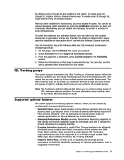
...for capacity planning. You can activate by optimizing the internal switch buffers to maintain performance on Demand license. Supported optional features The switch supports the following Web site: http://www.ibm.com/servers/ storage/support/san. 1. v Adaptive Networking- After you have ISL... models. This means that specifies the transaction key to use the supplied license key or generate a license key. Introducing the SAN40B-4 switch 5 On that page to generate the key. v Advanced Performance Monitor-provides Performance Monitoring capability to help identify end-to-end...
...for capacity planning. You can activate by optimizing the internal switch buffers to maintain performance on Demand license. Supported optional features The switch supports the following Web site: http://www.ibm.com/servers/ storage/support/san. 1. v Adaptive Networking- After you have ISL... models. This means that specifies the transaction key to use the supplied license key or generate a license key. Introducing the SAN40B-4 switch 5 On that page to generate the key. v Advanced Performance Monitor-provides Performance Monitoring capability to help identify end-to-end...

User Guide
Page 30
...optional features bundled into one of each of the supported SAN b-type switch, router, and supported IBM System z and zSeries servers. For more information on multiple switches and directors, each FC Router (FCR) connection when connected to ...another 8 Gbps capable port v FICON w/ CUP-designed to the Fabric OS Administrator's Guide. 6 SAN40B-4 Installation, Service, and User's Guide v Integrated Routing-allows any port in the switch...
...optional features bundled into one of each of the supported SAN b-type switch, router, and supported IBM System z and zSeries servers. For more information on multiple switches and directors, each FC Router (FCR) connection when connected to ...another 8 Gbps capable port v FICON w/ CUP-designed to the Fabric OS Administrator's Guide. 6 SAN40B-4 Installation, Service, and User's Guide v Integrated Routing-allows any port in the switch...
User Guide
Page 31
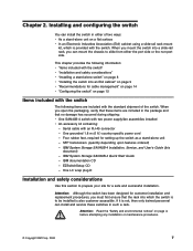
... a slide-rail rack, you can mount the chassis to be installed is not, then only trained personnel can install the switch in such a rack. IBM System Storage SAN40B-4 Quick Start Guide - IBM documentation CD - Attention: Although the switch has been designed for a safe and successful installation. If it is also customer accessible. Four rubber feet, required for...
... a slide-rail rack, you can mount the chassis to be installed is not, then only trained personnel can install the switch in such a rack. IBM System Storage SAN40B-4 Quick Start Guide - IBM documentation CD - Attention: Although the switch has been designed for a safe and successful installation. If it is also customer accessible. Four rubber feet, required for...

User Guide
Page 32
...cubic meters/hour) available on an ongoing basis, particularly if the switch is correctly wired, protected by the electrical rating on page 7 8 SAN40B-4 Installation, Service, and User's Guide v A minimum air flow of the switch, ensure that the following procedure: 1. v Verify that you can ...be a standard EIA cabinet. The switch can mount the chassis to slide from either ...
...cubic meters/hour) available on an ongoing basis, particularly if the switch is correctly wired, protected by the electrical rating on page 7 8 SAN40B-4 Installation, Service, and User's Guide v A minimum air flow of the switch, ensure that the following procedure: 1. v Verify that you can ...be a standard EIA cabinet. The switch can mount the chassis to slide from either ...
User Guide
Page 33
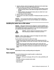
... corner of the bottom of the cabinet, allowing a more gradual bend in the fiber optic cables. In this installation, the port side of the switch is set 7.62 cm (3 in.) back from sliding off " on page 21. Provide power to "Rack safety" on page 15. Attention: Read... the "Safety and environmental notices" on a flat, sturdy surface. 4. You can install and service these switches in .) deep v One power cord that the rack into place. 3. Time required Approximately 30 minutes, excluding cabling and configuration Items required You need the ...
... corner of the bottom of the cabinet, allowing a more gradual bend in the fiber optic cables. In this installation, the port side of the switch is set 7.62 cm (3 in.) back from sliding off " on page 21. Provide power to "Rack safety" on page 15. Attention: Read... the "Safety and environmental notices" on a flat, sturdy surface. 4. You can install and service these switches in .) deep v One power cord that the rack into place. 3. Time required Approximately 30 minutes, excluding cabling and configuration Items required You need the ...

User Guide
Page 34
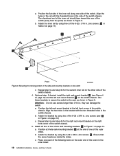
... 1 Detail A 2X 3 Front of screws are listed in Table 3 on page 11. Using screws longer than 3/16 in. The different types of Switch 7 2 2X Figure 4. These parts are listed in Table 3 on page 11. Before you perform each step. Attention: Use the exact screws specified ...in the procedure for a list of parts and the quantities supplied. 10 SAN40B-4 Installation, Service, and User's Guide Unpack the rack-mount kit and verify that you tighten all ordered items and parts are included in...
... 1 Detail A 2X 3 Front of screws are listed in Table 3 on page 11. Using screws longer than 3/16 in. The different types of Switch 7 2 2X Figure 4. These parts are listed in Table 3 on page 11. Before you perform each step. Attention: Use the exact screws specified ...in the procedure for a list of parts and the quantities supplied. 10 SAN40B-4 Installation, Service, and User's Guide Unpack the rack-mount kit and verify that you tighten all ordered items and parts are included in...

User Guide
Page 35
...8 Bracket to the set of the slides until the lock engages. Install the inner (smaller) slide on page 10 shows. Installing and configuring the switch 11 b. Chapter 2. Note: For racks with the rack-mount kit Item 1 Description Rack mount slide (inner and outer slide) Quantity 2 2... rack mount bracket (optional bracket for the other rail. Instead, use screws longer than 3/16 in., you use the rack-mount slides by attaching the switch to slide rack kit (contains items 9 - 1 12) 9 Screw, 8-32 x 3/8 in., zinc 5 10 Washer, flat, No. 8 5 11 Washer, lock, No. 8 5 12 Nut,...
...8 Bracket to the set of the slides until the lock engages. Install the inner (smaller) slide on page 10 shows. Installing and configuring the switch 11 b. Chapter 2. Note: For racks with the rack-mount kit Item 1 Description Rack mount slide (inner and outer slide) Quantity 2 2... rack mount bracket (optional bracket for the other rail. Instead, use screws longer than 3/16 in., you use the rack-mount slides by attaching the switch to slide rack kit (contains items 9 - 1 12) 9 Screw, 8-32 x 3/8 in., zinc 5 10 Washer, flat, No. 8 5 11 Washer, lock, No. 8 5 12 Nut,...
User Guide
Page 36
... and step 4b for the second inner rail on page 11). 1 6 3 Front Figure 6. Attach the bracket by using the 8-32 x 3/8 in the order listed: 12 SAN40B-4 Installation, Service, and User's Guide c. Place one each of the following items on page 10) and the left front corner of the 8-32 x 3/16 in.... Attach all four of the outer slides. Position the left rack mount bracket at the end of one side of the switch chassis. Align the two holes in the bracket with the threaded holes in Figure 7 on page 10) c. Position a 3-hole rack mounting bracket 4 at the left ...
... and step 4b for the second inner rail on page 11). 1 6 3 Front Figure 6. Attach the bracket by using the 8-32 x 3/8 in the order listed: 12 SAN40B-4 Installation, Service, and User's Guide c. Place one each of the following items on page 10) and the left front corner of the 8-32 x 3/16 in.... Attach all four of the outer slides. Position the left rack mount bracket at the end of one side of the switch chassis. Align the two holes in the bracket with the threaded holes in Figure 7 on page 10) c. Position a 3-hole rack mounting bracket 4 at the left ...
User Guide
Page 37
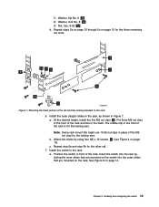
... rack by using four M5 x 12 screws 7 (see Figure 4 on the rack. Attach the slides by sliding the inner slides that are mounted on the switch into the outer slides that are mounted on page 10). See Figure 8 on page 12 for the locking ears. Chapter 2. Install the outer (larger) slides... rack mount kits might use 10-32 nut clips in Figure 7. Repeat step 6a and step 6b for the locking ears. Installing and configuring the switch 13 Repeat steps 5a on page 12 through 5c on page 14. At the desired height, install the five M5 nut clips 5 . Put three M5...
... rack by using four M5 x 12 screws 7 (see Figure 4 on the rack. Attach the slides by sliding the inner slides that are mounted on the switch into the outer slides that are mounted on page 10). See Figure 8 on page 12 for the locking ears. Chapter 2. Install the outer (larger) slides... rack mount kits might use 10-32 nut clips in Figure 7. Repeat step 6a and step 6b for the locking ears. Installing and configuring the switch 13 Repeat steps 5a on page 12 through 5c on page 14. At the desired height, install the five M5 nut clips 5 . Put three M5...
User Guide
Page 38
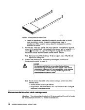
... 10-32 nut clips in and out of the customer to ensure that the default IP address does not conflict with no tensile load. 14 SAN40B-4 Installation, Service, and User's Guide v Verify that the outlet is correctly wired and grounded to prevent an electrical shock. (D004) Note: Do not ... rack mount brackets are installed on page 10. If this situation occurs, adjust the slide positions until you perform one of the switch, attach both brackets to the system. Check the alignment of each bracket and the slide rail. The screws should pass through the front of the slides by using...
... 10-32 nut clips in and out of the customer to ensure that the default IP address does not conflict with no tensile load. 14 SAN40B-4 Installation, Service, and User's Guide v Verify that the outlet is correctly wired and grounded to prevent an electrical shock. (D004) Note: Do not ... rack mount brackets are installed on page 10. If this situation occurs, adjust the slide positions until you perform one of the switch, attach both brackets to the system. Check the alignment of each bracket and the slide rail. The screws should pass through the front of the slides by using...
User Guide
Page 39
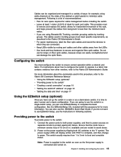
..., you do not want to less than the minimum bend radius. Configuring the switch You must meet specific requirements, as a stand-alone switch, it power and a basic configuration. You can use the SAN40B-4 Quick Start Guide. Installing and configuring the switch 15 v If you are routed to boot and complete POST. The power supply...
..., you do not want to less than the minimum bend radius. Configuring the switch You must meet specific requirements, as a stand-alone switch, it power and a basic configuration. You can use the SAN40B-4 Quick Start Guide. Installing and configuring the switch 15 v If you are routed to boot and complete POST. The power supply...
