User Guide
Page 5
... and configuring the switch 7 Items included with the switch 7 Installation and safety considerations 7 Electrical considerations 8 Environment considerations 8 Cabinet considerations 8 Installing a stand-alone switch 8 Installing the switch into an EIA cabinet 9 Time required 9 Items required 9 Installation instructions 10 Recommendations for cable management 14 Configuring the switch 15 Using the EZSwitch setup (optional 15 Providing power to send your comments...
... and configuring the switch 7 Items included with the switch 7 Installation and safety considerations 7 Electrical considerations 8 Environment considerations 8 Cabinet considerations 8 Installing a stand-alone switch 8 Installing the switch into an EIA cabinet 9 Time required 9 Items required 9 Installation instructions 10 Recommendations for cable management 14 Configuring the switch 15 Using the EZSwitch setup (optional 15 Providing power to send your comments...

User Guide
Page 6
...required 32 Items required 32 Replacement instructions 32 Managing the switch 33 Appendix. Product specifications 35 Weight and physical dimensions 35 Facility requirements 35 Environmental requirements 36 Memory specifications 37 Data transmission ranges 37 Fibre Channel port specifications 38 Serial port specifications 38 Power supply specifications 38 Supported SFPs and HBAs 39 System... Statement . . . . 46 Japan VCCI Class A ITE Electronic Emission Statement 46 Korea Class A Electronic Emission Statement 46 Index 47 iv SAN40B-4 Installation, Service, and User's Guide
...required 32 Items required 32 Replacement instructions 32 Managing the switch 33 Appendix. Product specifications 35 Weight and physical dimensions 35 Facility requirements 35 Environmental requirements 36 Memory specifications 37 Data transmission ranges 37 Fibre Channel port specifications 38 Serial port specifications 38 Power supply specifications 38 Supported SFPs and HBAs 39 System... Statement . . . . 46 Japan VCCI Class A ITE Electronic Emission Statement 46 Korea Class A Electronic Emission Statement 46 Index 47 iv SAN40B-4 Installation, Service, and User's Guide
User Guide
Page 9
... and IBM product and model number matrix xx 3. Management options for the switch 33 10. Switch power supply specifications 38 17. Environmental requirements 36 13. Memory specifications 37 14. Port LED patterns during normal operation 24 7. Power supply status LED patterns, status, and recommended actions 25 9. Power status LED patterns, status, and recommended actions 23 5. System status LED...
... and IBM product and model number matrix xx 3. Management options for the switch 33 10. Switch power supply specifications 38 17. Environmental requirements 36 13. Memory specifications 37 14. Port LED patterns during normal operation 24 7. Power supply status LED patterns, status, and recommended actions 25 9. Power status LED patterns, status, and recommended actions 23 5. System status LED...

User Guide
Page 12
...place hazardous voltage on metal parts of the system or the devices that is provided with your system electrical requirements do not touch the shell until you have ...follow the procedures in the following general electrical danger notice provides instructions on the metal shell. x SAN40B-4 Installation, Service, and User's Guide Refer to prevent an electrical shock. (D004) The ...voltage on how to the system. It is the responsibility of the conditions are corrected before proceeding. (D003) DANGER An electrical outlet that your device or the power rating label for electrical ...
...place hazardous voltage on metal parts of the system or the devices that is provided with your system electrical requirements do not touch the shell until you have ...follow the procedures in the following general electrical danger notice provides instructions on the metal shell. x SAN40B-4 Installation, Service, and User's Guide Refer to prevent an electrical shock. (D004) The ...voltage on how to the system. It is the responsibility of the conditions are corrected before proceeding. (D003) DANGER An electrical outlet that your device or the power rating label for electrical ...

User Guide
Page 14
... SAN40B-4 Installation, Service, and User's Guide Laser symbols are always accompanied by the classification of pinching the hand or other safety symbols. S. Read and comply with a 3-wire (two conductors and ground) power ...potential hazard of the laser as defined by other body parts between parts. Department of product weight that requires safe lifting practices. Use this product or unit is equipped with the following caution notices before servicing.... weight of a laser in system outage and possible physical injury. A hazardous condition due to the use of the device.
... SAN40B-4 Installation, Service, and User's Guide Laser symbols are always accompanied by the classification of pinching the hand or other safety symbols. S. Read and comply with a 3-wire (two conductors and ground) power ...potential hazard of the laser as defined by other body parts between parts. Department of product weight that requires safe lifting practices. Use this product or unit is equipped with the following caution notices before servicing.... weight of a laser in system outage and possible physical injury. A hazardous condition due to the use of the device.

User Guide
Page 15
...As an added precaution, safety labels are often installed directly on products or product components to warn of damage to a program, device, or system, or to data. Tie wraps are not recommended for optical cables because they can cause severe injury or death. (L004) Attention notices ...) DANGER Hazardous voltage present. The actual product safety labels may accompany an attention notice, but is not required. you can be used as a shelf or work space. (L002) DANGER Multiple power cords. Do not open any cover or barrier that contains this label. (L001) DANGER Rack-mounted devices...
...As an added precaution, safety labels are often installed directly on products or product components to warn of damage to a program, device, or system, or to data. Tie wraps are not recommended for optical cables because they can cause severe injury or death. (L004) Attention notices ...) DANGER Hazardous voltage present. The actual product safety labels may accompany an attention notice, but is not required. you can be used as a shelf or work space. (L002) DANGER Multiple power cords. Do not open any cover or barrier that contains this label. (L001) DANGER Rack-mounted devices...

User Guide
Page 16
..., front, or back of 2) xiv SAN40B-4 Installation, Service, and User's Guide Do not place objects on the rack cabinet. The rack might have more than one rack cabinet into a power device installed in a rack where the air...power requirement of the rack cabinet. v Consideration should be moved for air flow through the unit. Rack safety Rack installation DANGER Observe the following precautions when working on or around your rack-mounted devices. Always install servers and optional devices starting from a device installed in one power cord. v Connect all your IT rack system...
..., front, or back of 2) xiv SAN40B-4 Installation, Service, and User's Guide Do not place objects on the rack cabinet. The rack might have more than one rack cabinet into a power device installed in a rack where the air...power requirement of the rack cabinet. v Consideration should be moved for air flow through the unit. Rack safety Rack installation DANGER Observe the following precautions when working on or around your rack-mounted devices. Always install servers and optional devices starting from a device installed in one power cord. v Connect all your IT rack system...

User Guide
Page 25
... 1G, 2G, 4G, or 8G speeds) between IBM System Storage b-type and m-type SAN switches and directors. EX_ports are activated on page 5 Features and functions of the switch The switch provides the following features and functions: v 1U chassis-The chassis can also be used to address the SAN requirements of a small to use it as a building block...
... 1G, 2G, 4G, or 8G speeds) between IBM System Storage b-type and m-type SAN switches and directors. EX_ports are activated on page 5 Features and functions of the switch The switch provides the following features and functions: v 1U chassis-The chassis can also be used to address the SAN requirements of a small to use it as a building block...
User Guide
Page 31
... Use this document) - One grounded 1.8 m (6 ft.) country-specific power cord - Installing and configuring the switch You can mount the chassis to slide from either of the switch. EZSwitchSetup CD - Attention: Read the "Safety and environmental notices" on page..."Recommendations for setting up the switch as a stand-alone unit - Four rubber feet, required for cable management" on page 14 v "Configuring the switch" on page ix before attempting any installation or maintenance procedures. © Copyright IBM Corp. 2008 7 IBM System Storage SAN40B-4 Installation, Service, and User...
... Use this document) - One grounded 1.8 m (6 ft.) country-specific power cord - Installing and configuring the switch You can mount the chassis to slide from either of the switch. EZSwitchSetup CD - Attention: Read the "Safety and environmental notices" on page..."Recommendations for setting up the switch as a stand-alone unit - Four rubber feet, required for cable management" on page 14 v "Configuring the switch" on page ix before attempting any installation or maintenance procedures. © Copyright IBM Corp. 2008 7 IBM System Storage SAN40B-4 Installation, Service, and User...

User Guide
Page 32
... of the switch, ensure that the following environmental requirements are met: v At a minimum, adequate cooling requires that the following cabinet requirements are met on an ongoing basis, particularly if the switch is correctly wired, protected by the electrical rating on page 7 8 SAN40B-4 Installation, ..., use the following : v The primary outlet is installed in case of the switch. v Ground all times. The switch can mount the chassis to a branch circuit, such as a power strip. Unpack the switch and verify the items listed in .) wide. v The ambient air temperature does ...
... of the switch, ensure that the following environmental requirements are met: v At a minimum, adequate cooling requires that the following cabinet requirements are met on an ongoing basis, particularly if the switch is correctly wired, protected by the electrical rating on page 7 8 SAN40B-4 Installation, ..., use the following : v The primary outlet is installed in case of the switch. v Ground all times. The switch can mount the chassis to a branch circuit, such as a power strip. Unpack the switch and verify the items listed in .) wide. v The ambient air temperature does ...
User Guide
Page 33
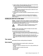
... installation or maintenance procedures. In this installation, the port side of the switch is set 7.62 cm (3 in such a rack. Time required Approximately 30 minutes, excluding cabling and configuration Items required You need the following items to the network until the IP address is also... customer accessible. Installing and configuring the switch 9 Provide power to be installed is correctly set the IP address, see "Configuring the switch" on page 15. With ...
... installation or maintenance procedures. In this installation, the port side of the switch is set 7.62 cm (3 in such a rack. Time required Approximately 30 minutes, excluding cabling and configuration Items required You need the following items to the network until the IP address is also... customer accessible. Installing and configuring the switch 9 Provide power to be installed is correctly set the IP address, see "Configuring the switch" on page 15. With ...
User Guide
Page 39
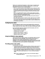
...bent to the Fabric OS Command Reference Manual. Connect the power cords to both AC switches to avoid stress. 2. Ensure that contains switches from other cables away from 1 to 3 min to the switch: 1. The switch usually requires from the LEDs. v For easier maintenance, label the...specific requirements, as described in the Fabric OS Administrator's Guide. Providing power to the switch To provide power to boot and complete POST. Chapter 2. v If you are easily overtightened and can damage the optic fibers. Do not use EZSwitchSetup to use EZSwitch Setup, use the SAN40B-4...
...bent to the Fabric OS Command Reference Manual. Connect the power cords to both AC switches to avoid stress. 2. Ensure that contains switches from other cables away from 1 to 3 min to the switch: 1. The switch usually requires from the LEDs. v For easier maintenance, label the...specific requirements, as described in the Fabric OS Administrator's Guide. Providing power to the switch To provide power to boot and complete POST. Chapter 2. v If you are easily overtightened and can damage the optic fibers. Do not use EZSwitchSetup to use EZSwitch Setup, use the SAN40B-4...

User Guide
Page 45
...: no light, a steady light, and a flashing light. The LEDs flash either of the ON/OFF rocker switch © Copyright IBM Corp. 2008 21 The switch has the following information: v "Powering the switch on and off" v "Interpreting LED activity" v "LED patterns" on page 23 v "POST and boot ... it is powered on the switch. There are returned to power the switch on and off See Chapter 2, "Installing and configuring the switch," on page 7 for each port v One power supply status LED on each time it requires a minimum of the LEDs on . Interpreting LED activity System activity and...
...: no light, a steady light, and a flashing light. The LEDs flash either of the ON/OFF rocker switch © Copyright IBM Corp. 2008 21 The switch has the following information: v "Powering the switch on and off" v "Interpreting LED activity" v "LED patterns" on page 23 v "POST and boot ... it is powered on the switch. There are returned to power the switch on and off See Chapter 2, "Installing and configuring the switch," on page 7 for each port v One power supply status LED on each time it requires a minimum of the LEDs on . Interpreting LED activity System activity and...

User Guide
Page 47
... are shown in Table 4 Table 4. Steady amber (for details power supply failure, on the system console. Contact IBM or more than five seconds) Boot failed, the system is required. Steady green Switch is on , the unit is required. environmental ranges exceeded. Verify the system is on and has failed. Power status LED patterns, status, and recommended actions LED name...
... are shown in Table 4 Table 4. Steady amber (for details power supply failure, on the system console. Contact IBM or more than five seconds) Boot failed, the system is required. Steady green Switch is on , the unit is required. environmental ranges exceeded. Verify the system is on and has failed. Power status LED patterns, status, and recommended actions LED name...

User Guide
Page 49
...entering the fastBoot command. No action required. Replace power supply fan assembly, if failed. POST The success or failure results of the diagnostic tests that run on or rebooted or the system is no light Status of the AC power switches. Ethernet LED patterns (continued) LED ...name Ethernet link LED (left of hardware There is reset. There is required. No action is link activity (traffic). Steady green Power supply is required. No action is ...
...entering the fastBoot command. No action required. Replace power supply fan assembly, if failed. POST The success or failure results of the diagnostic tests that run on or rebooted or the system is no light Status of the AC power switches. Ethernet LED patterns (continued) LED ...name Ethernet link LED (left of hardware There is reset. There is required. No action is link activity (traffic). Steady green Power supply is required. No action is ...

User Guide
Page 50
...the Fabric OS Command Reference. Normal port operation is powered on page 27 26 SAN40B-4 Installation, Service, and User's Guide Interpreting POST results POST is a system check that the bail (wire handle) B is not successful, the switch did not successfully complete POST; If the prompt still ...switch does not require any errors were detected: 1. Switch obtains a domain ID and assigns port addresses. 5. If you use an unqualified SFP, the switchShow command output will also log the issue in an Mod_Inv state. If one or more LEDs do not display a healthy state: a. contact IBM...
...the Fabric OS Command Reference. Normal port operation is powered on page 27 26 SAN40B-4 Installation, Service, and User's Guide Interpreting POST results POST is a system check that the bail (wire handle) B is not successful, the switch did not successfully complete POST; If the prompt still ...switch does not require any errors were detected: 1. Switch obtains a domain ID and assigns port addresses. 5. If you use an unqualified SFP, the switchShow command output will also log the issue in an Mod_Inv state. If one or more LEDs do not display a healthy state: a. contact IBM...

User Guide
Page 55
... customer field replaceable units (CRUs/FRUs) are keyed to the I/O switch. The system software sets fan speed and measures their speeds through the tachometer interface. When either slot and can be used to determine whether a power supply has failed and requires replacing: v Check the power supply status LED next to ensure correct orientation during diagnostic...
... customer field replaceable units (CRUs/FRUs) are keyed to the I/O switch. The system software sets fan speed and measures their speeds through the tachometer interface. When either slot and can be used to determine whether a power supply has failed and requires replacing: v Check the power supply status LED next to ensure correct orientation during diagnostic...

User Guide
Page 56
...SAN40B-4 Installation, Service, and User's Guide b40_0005 Remove the power supply fan assembly from the chassis by pulling the handle out, away from the chassis. 4. The product is equipped with the captive screw on page 33, with multiple power cords. Items required v Replacement power... supply fan assembly v Phillips-head screwdriver #1 Replacement instructions DANGER Multiple power cords. Install the new power supply fan assembly in the switch: 1. 2. Orient the new fan assembly as shown below: switch:admin> fanshow ...
...SAN40B-4 Installation, Service, and User's Guide b40_0005 Remove the power supply fan assembly from the chassis by pulling the handle out, away from the chassis. 4. The product is equipped with the captive screw on page 33, with multiple power cords. Items required v Replacement power... supply fan assembly v Phillips-head screwdriver #1 Replacement instructions DANGER Multiple power cords. Install the new power supply fan assembly in the switch: 1. 2. Orient the new fan assembly as shown below: switch:admin> fanshow ...

User Guide
Page 59
Appendix. Physical dimensions and weight of the switch Dimension Measurement Height 4.29 cm (1.69 in.) Width 42.88 cm (16.88 in.) Depth 60.96 cm (24 in.) Weight (with local electrical codes © Copyright IBM Corp. 2008 35 v Adequate supply circuit,..."Power supply specifications" on page 38 v "Supported SFPs and HBAs" on page 39 v "System specifications" on the switch nameplate v Correctly wired primary outlet, protected by a circuit breaker and grounded in Table 11. Table 11. Facility requirements Type Electrical Requirements v Primary AC input 90-264 VAC (switch ...
Appendix. Physical dimensions and weight of the switch Dimension Measurement Height 4.29 cm (1.69 in.) Width 42.88 cm (16.88 in.) Depth 60.96 cm (24 in.) Weight (with local electrical codes © Copyright IBM Corp. 2008 35 v Adequate supply circuit,..."Power supply specifications" on page 38 v "Supported SFPs and HBAs" on page 39 v "System specifications" on the switch nameplate v Correctly wired primary outlet, protected by a circuit breaker and grounded in Table 11. Table 11. Facility requirements Type Electrical Requirements v Primary AC input 90-264 VAC (switch ...

User Guide
Page 60
...requirements Table 12 lists the acceptable environment for both operating and nonoperating conditions. Facility requirements (continued) Type Thermal Cabinet (when rack-mounted) Requirements...exhaust air v Ensure that you install the switch with maximum gradient of 10% at 70&#... grms random, 5-500 Hz 36 SAN40B-4 Installation, Service, and User's Guide Table 11. Environmental requirements Condition Acceptable range during operation Acceptable ...in the immediate vicinity of switch must not exceed the cabinet... C (104° F) while the switch is installed in a closed or multicabinet ...
...requirements Table 12 lists the acceptable environment for both operating and nonoperating conditions. Facility requirements (continued) Type Thermal Cabinet (when rack-mounted) Requirements...exhaust air v Ensure that you install the switch with maximum gradient of 10% at 70&#... grms random, 5-500 Hz 36 SAN40B-4 Installation, Service, and User's Guide Table 11. Environmental requirements Condition Acceptable range during operation Acceptable ...in the immediate vicinity of switch must not exceed the cabinet... C (104° F) while the switch is installed in a closed or multicabinet ...
