
Instruction Manual
Page 1
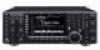
HF/50 MHz TRANSCEIVER i7700 Instruction Manual A-6612H-1EX-q Printed in Japan © 2008 Icom Inc.
HF/50 MHz TRANSCEIVER i7700 Instruction Manual A-6612H-1EX-q Printed in Japan © 2008 Icom Inc.
Instruction Manual
Page 2
..., the United Kingdom, Germany, France, Spain, Russia and/or other countries. TRADEMARKS Icom, Icom Inc. However, there is connected. • Consult the dealer or an experienced radio/TV technician for the IC-7700. This equipment generates, uses and can be a little difficult to correct the interference...found to part 15 of your radio of "technology first." i No risk of Icom Incorporated (Japan) in accordance with Icom's philosophy of choice. and the logo are designed to operate the transceiver. Many hours of research and development went into an outlet on , the user...
..., the United Kingdom, Germany, France, Spain, Russia and/or other countries. TRADEMARKS Icom, Icom Inc. However, there is connected. • Consult the dealer or an experienced radio/TV technician for the IC-7700. This equipment generates, uses and can be a little difficult to correct the interference...found to part 15 of your radio of "technology first." i No risk of Icom Incorporated (Japan) in accordance with Icom's philosophy of choice. and the logo are designed to operate the transceiver. Many hours of research and development went into an outlet on , the user...
Instruction Manual
Page 3
... or any cooling vents on a slanted surface or vibrated place). cohol when cleaning the IC-7700, as possible from the AC outlet when you use a linear amplifier, set - AVOID placing the transceiver in excessively dusty environments or in an electric shock or damage to this device, not ... or touch the trans- R CAUTION! This may result in any problems caused by Icom Inc., could void your Icom dealer or distributor for long periods. If you will be easily accessible. The transceiver warranty does not cover any unstable place (such as small dark or light spots. ...
... or any cooling vents on a slanted surface or vibrated place). cohol when cleaning the IC-7700, as possible from the AC outlet when you use a linear amplifier, set - AVOID placing the transceiver in excessively dusty environments or in an electric shock or damage to this device, not ... or touch the trans- R CAUTION! This may result in any problems caused by Icom Inc., could void your Icom dealer or distributor for long periods. If you will be easily accessible. The transceiver warranty does not cover any unstable place (such as small dark or light spots. ...

Instruction Manual
Page 9
...-24 ■ Deleting a file 12-25 ■ Unmounting USB-Memory 12-25 ■ Formatting the USB-Memory 12-26 Section 13 MAINTENANCE ■ Troubleshooting 13-2 D Transceiver power 13-2 D Transmit and receive 13-2 D Scanning 13-3 D Display 13-3 D Format USB-Memory 13-3 ■ Main dial brake adjustment 13-3 ■ SWR reading 13-4 ■...
...-24 ■ Deleting a file 12-25 ■ Unmounting USB-Memory 12-25 ■ Formatting the USB-Memory 12-26 Section 13 MAINTENANCE ■ Troubleshooting 13-2 D Transceiver power 13-2 D Transmit and receive 13-2 D Scanning 13-3 D Display 13-3 D Format USB-Memory 13-3 ■ Main dial brake adjustment 13-3 ■ SWR reading 13-4 ■...
Instruction Manual
Page 12
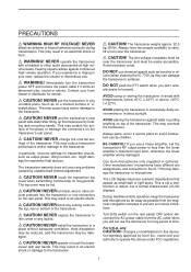
The internal power supply switch is located on the rear panel. (p. 3-2) ➥ Push to turn the transceiver power OFF. • The [POWER] indicator lights orange when the transceiver is OFF when the internal power supply is switched ON. See [CW KEY] on p. 1-12. • Keyer polarity (dot .... (p. 4-12) • A 4-channel memory keyer is available for 1 sec. y ELECTRONIC KEYER JACK [ELEC-KEY] (p. 2-5) Accepts a paddle to turn the transceiver power ON. • The [POWER] indicator above this switch lights green when the tuner is turned ON, goes off when tuner is turned OFF (bypassed...
The internal power supply switch is located on the rear panel. (p. 3-2) ➥ Push to turn the transceiver power OFF. • The [POWER] indicator lights orange when the transceiver is OFF when the internal power supply is switched ON. See [CW KEY] on p. 1-12. • Keyer polarity (dot .... (p. 4-12) • A 4-channel memory keyer is available for 1 sec. y ELECTRONIC KEYER JACK [ELEC-KEY] (p. 2-5) Accepts a paddle to turn the transceiver power ON. • The [POWER] indicator above this switch lights green when the tuner is turned ON, goes off when tuner is turned OFF (bypassed...

Instruction Manual
Page 14
...the function is in use. Audio output decreases Audio output increases 1-4 1 PANEL DESCRIPTION ■ Front panel (continued) !7 !8 POWER HF/50MHz TRANSCEIVER i7700 TRANSMIT TUNER VOX BK-IN MONITOR MIC RF PWR KEY SPEED DELAY TIMER PHONES AGC SQL NR NB ELEC-KEY MIC AGC VR NR...when the transceiver reads or writes to the memory data. • Unmount operation should be performed before removing the USB-Memory* (p.12-25). ➥ Connects a PC keyboard for RTTY and PSK31 operations. • USB keyboards* are supported. *: USB-Memory or USB keyboard is not supplied by Icom. @1 ...
...the function is in use. Audio output decreases Audio output increases 1-4 1 PANEL DESCRIPTION ■ Front panel (continued) !7 !8 POWER HF/50MHz TRANSCEIVER i7700 TRANSMIT TUNER VOX BK-IN MONITOR MIC RF PWR KEY SPEED DELAY TIMER PHONES AGC SQL NR NB ELEC-KEY MIC AGC VR NR...when the transceiver reads or writes to the memory data. • Unmount operation should be performed before removing the USB-Memory* (p.12-25). ➥ Connects a PC keyboard for RTTY and PSK31 operations. • USB keyboards* are supported. *: USB-Memory or USB keyboard is not supplied by Icom. @1 ...

Instruction Manual
Page 20
This transceiver uses the DSP circuit for the PBT function. to clear the PBT settings. • Adjustment range is set to reject interference. PBT2 PBT1 - + &1 &0 ^9 ^2 PBT CLEAR ...
This transceiver uses the DSP circuit for the PBT function. to clear the PBT settings. • Adjustment range is set to reject interference. PBT2 PBT1 - + &1 &0 ^9 ^2 PBT CLEAR ...
Instruction Manual
Page 22
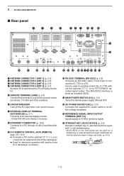
... CI-V LEVEL CONVERTER for external control of the transceiver. ➥ Used for transceive operation with another Icom CI-V transceiver or receiver. !0 RS-232C TERMINAL [RS-232C] (p. 2-6) Connects an RS-232C cable, D-sub 9-pin to connect the IC-7700 to prevent electrical shocks, TVI, BCI and other... 2-5) Accepts a straight key or external electronic keyer with a PL-259 plug connector. i ETHERNET CONNECTOR (p. 16-6) Connects to remotely control the IC-7700 without the optional CT-17, or for a straight key or external electronic keyer. SP ACC 2 1 RELAY ALC ALC ADJ S/P DIF OUT ...
... CI-V LEVEL CONVERTER for external control of the transceiver. ➥ Used for transceive operation with another Icom CI-V transceiver or receiver. !0 RS-232C TERMINAL [RS-232C] (p. 2-6) Connects an RS-232C cable, D-sub 9-pin to connect the IC-7700 to prevent electrical shocks, TVI, BCI and other... 2-5) Accepts a straight key or external electronic keyer with a PL-259 plug connector. i ETHERNET CONNECTOR (p. 16-6) Connects to remotely control the IC-7700 without the optional CT-17, or for a straight key or external electronic keyer. SP ACC 2 1 RELAY ALC ALC ADJ S/P DIF OUT ...
Instruction Manual
Page 23
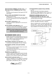
OUT] (p. 2-7) Connects external equipment that supports S/P DIF input/output. !7 ALC LEVEL ADJUSTMENT POT [ALC ADJ] Adjusts the ALC levels. Transceiver mute control line (both transmit and receive) is in use. (pgs. 2-11) @7 RECEIVE ANTENNA IN [RX ANT- Activated by the...or RF filter, using BNC connectors, if desired. IN] (p. 2-7) !6 S/P DIF OUTPUT TERMINAL [S/P DIF- No adjustment is required when the ALC output level of a connected non-Icom linear amplifier is 0 to -4 V a DC. !8 ALC INPUT JACK [ALC] (p. 2-8) Connects to [ACC 2] pin 6, or when the transverter function is also supported. ...
OUT] (p. 2-7) Connects external equipment that supports S/P DIF input/output. !7 ALC LEVEL ADJUSTMENT POT [ALC ADJ] Adjusts the ALC levels. Transceiver mute control line (both transmit and receive) is in use. (pgs. 2-11) @7 RECEIVE ANTENNA IN [RX ANT- Activated by the...or RF filter, using BNC connectors, if desired. IN] (p. 2-7) !6 S/P DIF OUTPUT TERMINAL [S/P DIF- No adjustment is required when the ALC output level of a connected non-Icom linear amplifier is 0 to -4 V a DC. !8 ALC INPUT JACK [ALC] (p. 2-8) Connects to [ACC 2] pin 6, or when the transverter function is also supported. ...

Instruction Manual
Page 27
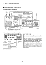
... D Front panel 2-6 D Rear panel-1 2-6 D Rear panel-2 2-7 ■ Linear amplifier connections 2-8 D Connecting the IC-PW1/EURO 2-8 D Connecting a non-Icom linear amplifier 2-8 ■ Transverter jack information 2-9 ■ FSK and AFSK (SSTV) connections 2-9 ■ Microphone connector ...information 2-10 ■ Microphones (options 2-10 D SM-20 2-10 D HM-36 2-10 ■ Accessory connector information 2-11 CAUTION!: The transceiver...
... D Front panel 2-6 D Rear panel-1 2-6 D Rear panel-2 2-7 ■ Linear amplifier connections 2-8 D Connecting the IC-PW1/EURO 2-8 D Connecting a non-Icom linear amplifier 2-8 ■ Transverter jack information 2-9 ■ FSK and AFSK (SSTV) connections 2-9 ■ Microphone connector ...information 2-10 ■ Microphones (options 2-10 D SM-20 2-10 D HM-36 2-10 ■ Accessory connector information 2-11 CAUTION!: The transceiver...
Instruction Manual
Page 28
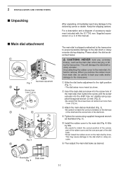
... Be careful to match the correct orientation of the flat face of the shaft and the screw hole of accessory equipment included with the IC-7700, see 'Supplied accessories' on the main dial by force. This will damage the dial shaft or rotary encoder. Front side Side view... the dial brake adjustment to the delivering carrier or dealer. y Then adjust the main dial brake as the main dial, when carrying or lifting the transceiver. 2 INSTALLATION AND CONNECTIONS ■ Unpacking ■ Main dial attachment q Dial brake adjustment Fig. 1 w Shorter than 1 mm (1/32 in ) Fig. 2 e r...
... Be careful to match the correct orientation of the flat face of the shaft and the screw hole of accessory equipment included with the IC-7700, see 'Supplied accessories' on the main dial by force. This will damage the dial shaft or rotary encoder. Front side Side view... the dial brake adjustment to the delivering carrier or dealer. y Then adjust the main dial brake as the main dial, when carrying or lifting the transceiver. 2 INSTALLATION AND CONNECTIONS ■ Unpacking ■ Main dial attachment q Dial brake adjustment Fig. 1 w Shorter than 1 mm (1/32 in ) Fig. 2 e r...

Instruction Manual
Page 29
...2-3 2 INSTALLATION AND CONNECTIONS ■ Rack mounting handle detachment q FH: Flat head PH: Pan head The rack mounting handles are supplied attached to the transceiver to remove them, use . FH M4 × 9 mm q Remove the six screws from TV sets, TV antenna elements, radios and other electromagnetic ...sources. If you want to stabilize the transceiver in the shock absorber material in the box. The base of two angles depending on both side and remove the rack mounting handles.
...2-3 2 INSTALLATION AND CONNECTIONS ■ Rack mounting handle detachment q FH: Flat head PH: Pan head The rack mounting handles are supplied attached to the transceiver to remove them, use . FH M4 × 9 mm q Remove the six screws from TV sets, TV antenna elements, radios and other electromagnetic ...sources. If you want to stabilize the transceiver in the shock absorber material in the box. The base of two angles depending on both side and remove the rack mounting handles.
Instruction Manual
Page 30
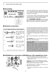
...the connector body on the rear panel. The transmission line should be increased out-of Voltage Standing Wave Ratio (VSWR) on your transceiver from lightning by Icom. 2-4 CAUTION: Protect your operating bands. When the SWR is useful to connect the USB-Memory correctly. Make the distance between the...10 mm (soft solder) tin the braid. Tin the 1-2 mm center conductor. The IC-7700 has an SWR meter to monitor the antenna SWR continuously. ■ USB-Memory connection (USB-Memory: Not supplied by Icom) Connect the USB-Memory* to the USB connector. • Unmount operation is not...
...the connector body on the rear panel. The transmission line should be increased out-of Voltage Standing Wave Ratio (VSWR) on your transceiver from lightning by Icom. 2-4 CAUTION: Protect your operating bands. When the SWR is useful to connect the USB-Memory correctly. Make the distance between the...10 mm (soft solder) tin the braid. Tin the 1-2 mm center conductor. The IC-7700 has an SWR meter to monitor the antenna SWR continuously. ■ USB-Memory connection (USB-Memory: Not supplied by Icom) Connect the USB-Memory* to the USB connector. • Unmount operation is not...

Instruction Manual
Page 31
... cap when no antenna or external equipment is changed in keyer set mode. (p. 4-12) Microphones (p. 2-10) Optional SM-20 Optional HM-36 POWER HF/50MHz TRANSCEIVER i7700 TRANSMIT TUNER VOX BK-IN MONITOR MIC RF PWR KEY SPEED DELAY TIMER PHONES AGC SQL NR NB TX RX ELEC-KEY MIC AGC...
... cap when no antenna or external equipment is changed in keyer set mode. (p. 4-12) Microphones (p. 2-10) Optional SM-20 Optional HM-36 POWER HF/50MHz TRANSCEIVER i7700 TRANSMIT TUNER VOX BK-IN MONITOR MIC RF PWR KEY SPEED DELAY TIMER PHONES AGC SQL NR NB TX RX ELEC-KEY MIC AGC...

Instruction Manual
Page 32
.... External speaker (p. 15-4) SP-20 (option) 2-6 [RELAY], [ALC] (p. 2-8) Used for computer control and transceive operation. POWER HF/50MHz TRANSCEIVER i7700 TRANSMIT TUNER VOX BK-IN MONITOR MIC RF PWR KEY SPEED DELAY TIMER PHONES AGC SQL NR NB TX RX...2-8) Connects a linear amplifier, antenna selector, etc. [X-VERTER] Connects a transverter for V/UHF band use. [REMOTE], [RS-232C] (p. 14-2) Used for connecting a non-Icom linear amplifier. MIC The AFSK modulation signal can also be activated in the antenna set screen (p.10-5). SP ACC 2 1 RELAY ALC ALC ADJ S/P DIF OUT...
.... External speaker (p. 15-4) SP-20 (option) 2-6 [RELAY], [ALC] (p. 2-8) Used for computer control and transceive operation. POWER HF/50MHz TRANSCEIVER i7700 TRANSMIT TUNER VOX BK-IN MONITOR MIC RF PWR KEY SPEED DELAY TIMER PHONES AGC SQL NR NB TX RX...2-8) Connects a linear amplifier, antenna selector, etc. [X-VERTER] Connects a transverter for V/UHF band use. [REMOTE], [RS-232C] (p. 14-2) Used for connecting a non-Icom linear amplifier. MIC The AFSK modulation signal can also be activated in the antenna set screen (p.10-5). SP ACC 2 1 RELAY ALC ALC ADJ S/P DIF OUT...

Instruction Manual
Page 33
...;5% ±5% ±5% S1 S2 S3 S4 (T1/M1) (T2/M2) (T3/M3) (T4/M4) Mute switch: Mutes both transmission and reception when switched ON during transceive operation, etc. 2-7 DISPL AY 15A GND REMOTE RS-232C AC I /O 10MHz -10dBm [METER] Connects an external meter, etc. 3.5 (d) mm; 1⁄8″ plug [S/P DIF IN/OUT...
...;5% ±5% ±5% S1 S2 S3 S4 (T1/M1) (T2/M2) (T3/M3) (T4/M4) Mute switch: Mutes both transmission and reception when switched ON during transceive operation, etc. 2-7 DISPL AY 15A GND REMOTE RS-232C AC I /O 10MHz -10dBm [METER] Connects an external meter, etc. 3.5 (d) mm; 1⁄8″ plug [S/P DIF IN/OUT...
Instruction Manual
Page 34
... ANT1 ANT2 GND ACC 2 IC-PW1/EURO AC outlet Ground (Non-European versions: 100-120/220-240 V European version : 230 V) Transceiver *Optional D Connecting a non-Icom linear amplifier To an antenna ANT1 50 Ω RELAY coaxial cable Transceiver ALC RF OUTPUT RF INPUT SEND ALC Non-Icom linear amplifier R WARNING: Set the transceiver output power and linear...
... ANT1 ANT2 GND ACC 2 IC-PW1/EURO AC outlet Ground (Non-European versions: 100-120/220-240 V European version : 230 V) Transceiver *Optional D Connecting a non-Icom linear amplifier To an antenna ANT1 50 Ω RELAY coaxial cable Transceiver ALC RF OUTPUT RF INPUT SEND ALC Non-Icom linear amplifier R WARNING: Set the transceiver output power and linear...

Instruction Manual
Page 40
... [NB] : Max. clockwise [AF] : Max. clockwise [RF] : Max. This is still OFF and the power indicator lights orange. clockwise POWER HF/50MHz TRANSCEIVER i7700 TRANSMIT TUNER VOX BK-IN MONITOR MIC RF PWR KEY SPEED DELAY TIMER PHONES AGC SQL NR NB ELEC-KEY MIC AGC VR NR ...controls as shown in set mode to turn power ON. • The CPU is reset. • The CPU start-up takes approx. 5 sec. • The transceiver displays its initial VFO frequencies when resetting is complete. e Change the set mode settings after turning power ON. w While pushing and holding F-INPENT and MW...
... [NB] : Max. clockwise [AF] : Max. clockwise [RF] : Max. This is still OFF and the power indicator lights orange. clockwise POWER HF/50MHz TRANSCEIVER i7700 TRANSMIT TUNER VOX BK-IN MONITOR MIC RF PWR KEY SPEED DELAY TIMER PHONES AGC SQL NR NB ELEC-KEY MIC AGC VR NR ...controls as shown in set mode to turn power ON. • The CPU is reset. • The CPU start-up takes approx. 5 sec. • The transceiver displays its initial VFO frequencies when resetting is complete. e Change the set mode settings after turning power ON. w While pushing and holding F-INPENT and MW...

Instruction Manual
Page 43
3 BASIC OPERATIONS ■ Frequency setting D Tuning with the keypad Keypad The transceiver has a keypad for convenient frequency tuning. e Push F-INPENT to set the input frequency. • To cancel the input, push any other key (except ∫ or &#... • Push GENE • to deactivate the lock function. (see p. 5-17 for details) D Direct frequency entry with the main dial Band keys Main dial The transceiver has several tuning methods for direct frequency entry as described below. q Push the desired band key on the keypad 1-3 times. • 3 different frequencies can be...
3 BASIC OPERATIONS ■ Frequency setting D Tuning with the keypad Keypad The transceiver has a keypad for convenient frequency tuning. e Push F-INPENT to set the input frequency. • To cancel the input, push any other key (except ∫ or &#... • Push GENE • to deactivate the lock function. (see p. 5-17 for details) D Direct frequency entry with the main dial Band keys Main dial The transceiver has several tuning methods for direct frequency entry as described below. q Push the desired band key on the keypad 1-3 times. • 3 different frequencies can be...
Instruction Manual
Page 55
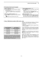
...must adhere to the following: • USB mode • Maximum of 50 watts ERP (Effective Radiated Power) • 2.8 kHz bandwidth IC-7700 Displayed Frequency* 5.33050 MHz 5.34650 MHz 5.36650 MHz 5.37150 MHz 5.40350 MHz FCC Channel Center Frequency* 5.33200 MHz 5.34800 MHz 5.36800...; Transmit quality monitor (p. 6-4) ➥ Push MONITOR to adjust the monitor gain. • Monitor indicator (above . However, the IC-7700 displays carrier frequency. Therefore, tune the transceiver to adjust the audio tone. sor ON and OFF. • Push and hold [COMP] (MF6) for transmit • Speech ...
...must adhere to the following: • USB mode • Maximum of 50 watts ERP (Effective Radiated Power) • 2.8 kHz bandwidth IC-7700 Displayed Frequency* 5.33050 MHz 5.34650 MHz 5.36650 MHz 5.37150 MHz 5.40350 MHz FCC Channel Center Frequency* 5.33200 MHz 5.34800 MHz 5.36800...; Transmit quality monitor (p. 6-4) ➥ Push MONITOR to adjust the monitor gain. • Monitor indicator (above . However, the IC-7700 displays carrier frequency. Therefore, tune the transceiver to adjust the audio tone. sor ON and OFF. • Push and hold [COMP] (MF6) for transmit • Speech ...
