
Instruction Manual
Page 1
INSTRUCTION MANUAL VHF AIR BAND TRANSCEIVER iA24 iA6 This device complies with Part 15 of the FCC Rules. IC-A24 IC-A6 Operation is subject to the condition that this device does not cause harmful interference.
INSTRUCTION MANUAL VHF AIR BAND TRANSCEIVER iA24 iA6 This device complies with Part 15 of the FCC Rules. IC-A24 IC-A6 Operation is subject to the condition that this device does not cause harmful interference.

Instruction Manual
Page 2
...may result in RF exposure levels exceeding the FCC requirements for occupational use the Icom belt-clips which persons are exposed as this radio. SAFETY TRAINING INFORMATION Your Icom radio generates RF electromagnetic energy during transmit mode. The radio is NOT intended for...Safety Levels with the FCC RF exposure limits of their exposure. In addition, your Icom radio generates RF energy that this product. Electromagnetic Interference/Compatibility During transmissions, your Icom radio complies with the following accessories are posted to do to exceed FCC RF ...
...may result in RF exposure levels exceeding the FCC requirements for occupational use the Icom belt-clips which persons are exposed as this radio. SAFETY TRAINING INFORMATION Your Icom radio generates RF electromagnetic energy during transmit mode. The radio is NOT intended for...Safety Levels with the FCC RF exposure limits of their exposure. In addition, your Icom radio generates RF energy that this product. Electromagnetic Interference/Compatibility During transmissions, your Icom radio complies with the following accessories are posted to do to exceed FCC RF ...

Instruction Manual
Page 3
... and craftsmanship. No risk of personal injury, fire or electric shock. With proper care this Icom product. CAUTION Equipment damage may occur. struction manual contains important operating instructions for purchasing this product should provide you for the IC-A24/A6. Some versions do not include a battery pack, wall charger, headset adapter or carrying...
... and craftsmanship. No risk of personal injury, fire or electric shock. With proper care this Icom product. CAUTION Equipment damage may occur. struction manual contains important operating instructions for purchasing this product should provide you for the IC-A24/A6. Some versions do not include a battery pack, wall charger, headset adapter or carrying...

Instruction Manual
Page 4
...power source that the antenna is the transceiver when not using or placing the transceiver in direct sunlight or headset or other countries. Icom, Icom Inc. in your authority to a transceiver performance and invalidate the warranty. If you experience a ringing in areas with any protection against...power is vertical. only) rent may impair NEVER connect the transceiver to an AC outlet or to NEVER short the terminals of non-Icom battery packs/chargers may flow into nearby metal objects, such as a necklace, etc. and the logo are registered trademarks of...
...power source that the antenna is the transceiver when not using or placing the transceiver in direct sunlight or headset or other countries. Icom, Icom Inc. in your authority to a transceiver performance and invalidate the warranty. If you experience a ringing in areas with any protection against...power is vertical. only) rent may impair NEVER connect the transceiver to an AC outlet or to NEVER short the terminals of non-Icom battery packs/chargers may flow into nearby metal objects, such as a necklace, etc. and the logo are registered trademarks of...

Instruction Manual
Page 5
... 24 7 BATTERY PACKS 25 - 27 I Battery charging 25 I Battery cautions 25 I Optional battery case 26 I Duplex operation (U.S.A. version only 17 I "TAG" channels 17 6 VOR NAVIGATION (IC-A24 only 18 - 24 I VOR indications 18 I VOR functions 19 I Flying to a VOR station 20 I Entering a desired course 22 I Crosschecking position 22 I Optional battery chargers 27...
... 24 7 BATTERY PACKS 25 - 27 I Battery charging 25 I Battery cautions 25 I Optional battery case 26 I Duplex operation (U.S.A. version only 17 I "TAG" channels 17 6 VOR NAVIGATION (IC-A24 only 18 - 24 I VOR indications 18 I VOR functions 19 I Flying to a VOR station 20 I Entering a desired course 22 I Crosschecking position 22 I Optional battery chargers 27...

Instruction Manual
Page 7
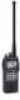
after 3 sec. 2 In this time pushing again cancels the indication. release to turn the power ON or OFF. ➥While pushing and holding [MR•MW], push [PWR] to se- lect the squelch level. • 24 squelch levels and squelch open (0) are available. ➥ Push , then push [SQL•WX-ALERT] to receive. • " " appears on the function display while transmitting. e VOLUME [VOL] (p. 9) Adjusts the audio level. r TUNING DIAL [DIAL] (pgs. 8-12) ➥ Rotate [DIAL] to select the desired frequency, WX channel number, BANK number and memory channel. ➥...
after 3 sec. 2 In this time pushing again cancels the indication. release to turn the power ON or OFF. ➥While pushing and holding [MR•MW], push [PWR] to se- lect the squelch level. • 24 squelch levels and squelch open (0) are available. ➥ Push , then push [SQL•WX-ALERT] to receive. • " " appears on the function display while transmitting. e VOLUME [VOL] (p. 9) Adjusts the audio level. r TUNING DIAL [DIAL] (pgs. 8-12) ➥ Rotate [DIAL] to select the desired frequency, WX channel number, BANK number and memory channel. ➥...

Instruction Manual
Page 8
... socket Wall charger Enters consecutive zero digits. (p. 8) ➥Push , then push [ENT•WX] to select the 121.5 MHz emergency frequency. • DC POWER CONNECTION IC-A24/A6 CP-20 (for 2 sec. to enter the weather channel selection mode (U.S.A.
... socket Wall charger Enters consecutive zero digits. (p. 8) ➥Push , then push [ENT•WX] to select the 121.5 MHz emergency frequency. • DC POWER CONNECTION IC-A24/A6 CP-20 (for 2 sec. to enter the weather channel selection mode (U.S.A.
Instruction Manual
Page 9
... set the displayed memory or weather channel as follows: Push , then push [0•BANK] to select the memory BANK number to rotate [DIAL] on the IC-A24 only. 4
... set the displayed memory or weather channel as follows: Push , then push [0•BANK] to select the memory BANK number to rotate [DIAL] on the IC-A24 only. 4

Instruction Manual
Page 10
The attached battery pack requires recharging. ➥ Appears and flashes when battery replacement is activated in use. r DUPLEX INDICATOR (IC-A24 only) (p. 24) ➥"DUP" appears when the duplex function is necessary. y LOCK INDICATOR (p. 11) Appears while the lock function is nearing exhaustion. t LOW BATTERY INDICATOR (p. ...
The attached battery pack requires recharging. ➥ Appears and flashes when battery replacement is activated in use. r DUPLEX INDICATOR (IC-A24 only) (p. 24) ➥"DUP" appears when the duplex function is necessary. y LOCK INDICATOR (p. 11) Appears while the lock function is nearing exhaustion. t LOW BATTERY INDICATOR (p. ...

Instruction Manual
Page 11
...appears when the memory channel is in CDI mode. !0 MEMORY BANK NUMBER INDICATOR (p. 12) Shows the selected memory bank number. !1 OVERFLOW INDICATOR (IC-A24 only) (pgs. 18-22) Appears when the deviation between the desired course and flying course is over 10 degrees. !5 TO-FROM INDICATOR... (IC-A24 only) (p. 19) Indicates whether the VOR navigation information is based on a VOR radial in use. !3 COURSE DEVIATION NEEDLES (IC-A24 only) (pgs. 18-22) Indicates the deviation between the desired course and your...
...appears when the memory channel is in CDI mode. !0 MEMORY BANK NUMBER INDICATOR (p. 12) Shows the selected memory bank number. !1 OVERFLOW INDICATOR (IC-A24 only) (pgs. 18-22) Appears when the deviation between the desired course and flying course is over 10 degrees. !5 TO-FROM INDICATOR... (IC-A24 only) (p. 19) Indicates whether the VOR navigation information is based on a VOR radial in use. !3 COURSE DEVIATION NEEDLES (IC-A24 only) (pgs. 18-22) Indicates the deviation between the desired course and your...

Instruction Manual
Page 12
Other- D Belt clip Conveniently attaches to turn the power OFF. Supplied screws D Battery pack replacement Before replacing the battery pack, push [PWR] for 2 sec. to your belt. Slide the battery release button forward, then pull the battery pack upward with the supplied screws as shown below . Insert the supplied antenna into the antenna connector and screw down the antenna as below . NOTE: Use the supplied screws only. wise the transceiver may be damaged. Attach the belt clip with the transceiver facing away from you. 7 2 ACCESSORY ATTACHMENT D Antenna CAUTION: DO NOT ...
Other- D Belt clip Conveniently attaches to turn the power OFF. Supplied screws D Battery pack replacement Before replacing the battery pack, push [PWR] for 2 sec. to your belt. Slide the battery release button forward, then pull the battery pack upward with the supplied screws as shown below . Insert the supplied antenna into the antenna connector and screw down the antenna as below . NOTE: Use the supplied screws only. wise the transceiver may be damaged. Attach the belt clip with the transceiver facing away from you. 7 2 ACCESSORY ATTACHMENT D Antenna CAUTION: DO NOT ...

Instruction Manual
Page 13
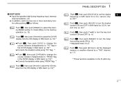
I Setting a squelch level ï Using keypad The transceiver has a noise squelch circuit to mute undesired 2 q Push [PWR] for 2 sec. Push again to frequency mode. • To select the 1 MHz tuning step, push , then rotate [DIAL]. 3 BASIC OPERATION I Setting a frequency I Selecting a weather channel (U.S.A. w Push [SQL•WX-ALERT] or [CLR•DEL] to exit the squelch set the desired frequency. then repeat step w again. • Push [ENT•WX] to enter consecutive zero digits. • Only [2]*, [5]*, [7• ] and [0•BANK] can be entered as the 1st ...
I Setting a squelch level ï Using keypad The transceiver has a noise squelch circuit to mute undesired 2 q Push [PWR] for 2 sec. Push again to frequency mode. • To select the 1 MHz tuning step, push , then rotate [DIAL]. 3 BASIC OPERATION I Setting a frequency I Selecting a weather channel (U.S.A. w Push [SQL•WX-ALERT] or [CLR•DEL] to exit the squelch set the desired frequency. then repeat step w again. • Push [ENT•WX] to enter consecutive zero digits. • Only [2]*, [5]*, [7• ] and [0•BANK] can be entered as the 1st ...

Instruction Manual
Page 14
w Push [SQL•WX-ALERT], then rotate [DIAL] counterclock- NOTE: To prevent interference, listen on the display while the ANL function is ON. 9 wise to adjust the audio level. To receive weaker signals, loosen the squelch I Transmitting CAUTION: Transmitting without an antenna may distort the signal. e Speak into the microphone at a normal voice level. • DO NOT hold [PTT] to transmit. • " " indicator appears. " " appears on the frequency before transmitting. t Set the desired frequency using [DIAL] or keypad. • COM band frequency range: 118.00-136.975 MHz ...
w Push [SQL•WX-ALERT], then rotate [DIAL] counterclock- NOTE: To prevent interference, listen on the display while the ANL function is ON. 9 wise to adjust the audio level. To receive weaker signals, loosen the squelch I Transmitting CAUTION: Transmitting without an antenna may distort the signal. e Speak into the microphone at a normal voice level. • DO NOT hold [PTT] to transmit. • " " indicator appears. " " appears on the frequency before transmitting. t Set the desired frequency using [DIAL] or keypad. • COM band frequency range: 118.00-136.975 MHz ...

Instruction Manual
Page 15
Appears recall number. • Recall number rotation : Push : Push NOTE: Deletes in order of old recall channel automatically when stored frequencies exceeds 10 channels. 10 I Low battery indicator Low battery indicator appears Low battery indicator when the battery power has decreased to a specified level. D Deletes the stored recall channel q Push or to call the 10th stored frequency. D Calling the stored frequencies ➥ Push to call the 1st stored frequency. ➥ Push to select the deleting recall channel. to replace it . • (e.g.) Deletes "r0" recall ...
Appears recall number. • Recall number rotation : Push : Push NOTE: Deletes in order of old recall channel automatically when stored frequencies exceeds 10 channels. 10 I Low battery indicator Low battery indicator appears Low battery indicator when the battery power has decreased to a specified level. D Deletes the stored recall channel q Push or to call the 10th stored frequency. D Calling the stored frequencies ➥ Push to call the 1st stored frequency. ➥ Push to select the deleting recall channel. to replace it . • (e.g.) Deletes "r0" recall ...
Instruction Manual
Page 16
... with the transceiver when using an optional headset, the transceiver outputs your ears may occur. If so, reduce the monitor level or discontinue use . The IC-A24 and IC-A6 can be - q Push [121.5] for long period. accidental function activation. erated. The previously selected (used) weather channel is checked any important weather announcements...
... with the transceiver when using an optional headset, the transceiver outputs your ears may occur. If so, reduce the monitor level or discontinue use . The IC-A24 and IC-A6 can be - q Push [121.5] for long period. accidental function activation. erated. The previously selected (used) weather channel is checked any important weather announcements...

Instruction Manual
Page 17
4 MEMORY OPERATION I Memory channel selection I Transferring memory The transceiver has 200 memory channels for signals 4 • Memory BANK number and memory CH. number appears. Using [DIAL]: w Push [0•BANK], then rotate [DIAL] to select the desired memory BANK number, then push [0•BANK] (or [CLR•DEL]) to exit the BANK-se- to [9•TAG]) to select the desired memory BANK number, then push [0•BANK] (or [CLR•DEL]) to exit the BANK selection mode. • "BANK" appears. selection is automatically selected and the memory contents are ...
4 MEMORY OPERATION I Memory channel selection I Transferring memory The transceiver has 200 memory channels for signals 4 • Memory BANK number and memory CH. number appears. Using [DIAL]: w Push [0•BANK], then rotate [DIAL] to select the desired memory BANK number, then push [0•BANK] (or [CLR•DEL]) to exit the BANK-se- to [9•TAG]) to select the desired memory BANK number, then push [0•BANK] (or [CLR•DEL]) to exit the BANK selection mode. • "BANK" appears. selection is automatically selected and the memory contents are ...

Instruction Manual
Page 18
version only. • EXAMPLE: Programming WX-05* into the selected memory channel. • Memory BANK and memory channel number appears. 4 MEMORY OPERATION I Programming a memory channel The transceiver has 200 (20 CH. × 10 BANK) memory channels for storage of often-used frequencies. Push Push or Push Push Push (or rotate [DIAL]) Push or Push or (or rotate [DIAL]) Push 13 w Select the desired frequency. • Push , then push [ENT•WX] to exit the BANK selection mode. • "M," BANK and memory numbers are blinks. e Push , then push [MR•MW] to ...
version only. • EXAMPLE: Programming WX-05* into the selected memory channel. • Memory BANK and memory channel number appears. 4 MEMORY OPERATION I Programming a memory channel The transceiver has 200 (20 CH. × 10 BANK) memory channels for storage of often-used frequencies. Push Push or Push Push Push (or rotate [DIAL]) Push or Push or (or rotate [DIAL]) Push 13 w Select the desired frequency. • Push , then push [ENT•WX] to exit the BANK selection mode. • "M," BANK and memory numbers are blinks. e Push , then push [MR•MW] to ...

Instruction Manual
Page 19
MEMORY OPERATION 4 I Memory names ï Programming memory names Key Character Key Character Key Character The memory channel can display a 6-character names instead of the programmed frequency. 1 1, Q, Z 2 2, A, B, C 3 3, D, E, F 4 4, G, H, I Clearing the memory contents Unwanted memory channels can be cleared. Push [CLR•DEL] to enter the memory name programming mode appears on the display. Programming over a memory channel also clears the previously programmed contents. r Push [MR•MW] to exit the BANK selection mode. I 5 5, J, K, L 6 6, M, N, O 4 q ...
MEMORY OPERATION 4 I Memory names ï Programming memory names Key Character Key Character Key Character The memory channel can display a 6-character names instead of the programmed frequency. 1 1, Q, Z 2 2, A, B, C 3 3, D, E, F 4 4, G, H, I Clearing the memory contents Unwanted memory channels can be cleared. Push [CLR•DEL] to enter the memory name programming mode appears on the display. Programming over a memory channel also clears the previously programmed contents. r Push [MR•MW] to exit the BANK selection mode. I 5 5, J, K, L 6 6, M, N, O 4 q ...

Instruction Manual
Page 20
Push [CLR•DEL] to select the BANK number, if desired. Push Push Push Push Push Push Push Push Push Push NOTE: Push [0•BANK], then rotate [DIAL] to continue memory name programming. 15 4 MEMORY OPERATION • EXAMPLE: Programming 125.000 MHz into memory BANK 1/ memory channel 17 with "AIR-23" as a comment.
Push [CLR•DEL] to select the BANK number, if desired. Push Push Push Push Push Push Push Push Push Push NOTE: Push [0•BANK], then rotate [DIAL] to continue memory name programming. 15 4 MEMORY OPERATION • EXAMPLE: Programming 125.000 MHz into memory BANK 1/ memory channel 17 with "AIR-23" as a comment.

Instruction Manual
Page 21
Used for the U.S.A. q Push [MR•MW] to select the frequency mode. e Push , then push [ANL•SCAN] to start the scan. 4 108.00 118.00 MHz MHz Repeatedly scans 136.975 MHz all "TAG" weather channels. r To stop the scan, push [CLR•DEL]. 5 Scan COM band. The q Push [CLR•DEL] to select memory mode. versions have 2 scan types. WEATHER CHANNEL SCAN Repeatedly scans all over frequencies the entire • When a signal is received, the scan pauses until it disappears. • To change the scanning direction, rotate [DIAL]. w Push [SQL...
Used for the U.S.A. q Push [MR•MW] to select the frequency mode. e Push , then push [ANL•SCAN] to start the scan. 4 108.00 118.00 MHz MHz Repeatedly scans 136.975 MHz all "TAG" weather channels. r To stop the scan, push [CLR•DEL]. 5 Scan COM band. The q Push [CLR•DEL] to select memory mode. versions have 2 scan types. WEATHER CHANNEL SCAN Repeatedly scans all over frequencies the entire • When a signal is received, the scan pauses until it disappears. • To change the scanning direction, rotate [DIAL]. w Push [SQL...
