Instruction Manual
Page 8
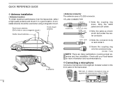
solder solder e Slide the connector body on the front panel of the IC-V8000. QUICK REFERENCE GUIDE D Antenna installation • Antenna location To obtain maximum performance from the transceiver, select a high-quality antenna and mount it . r Screw the coupling ring onto the connector body. (10 ... location. Check with some versions of the transceiver. *HM-133V; w Strip the cable as shown at left. III A nonradial antenna should be supplied with your local dealer for more information and recommendations. D Connecting a microphone Connect a microphone to the eight-pin ...
solder solder e Slide the connector body on the front panel of the IC-V8000. QUICK REFERENCE GUIDE D Antenna installation • Antenna location To obtain maximum performance from the transceiver, select a high-quality antenna and mount it . r Screw the coupling ring onto the connector body. (10 ... location. Check with some versions of the transceiver. *HM-133V; w Strip the cable as shown at left. III A nonradial antenna should be supplied with your local dealer for more information and recommendations. D Connecting a microphone Connect a microphone to the eight-pin ...
Instruction Manual
Page 16
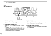
...; Audio output power is more than 2.0 W. NOTE: DO NOT use a cigarette lighter socket as a power source when operating in set mode and transceiver's temperature. (p. 61) r ANTENNA CONNECTOR [ANT] Connects a 50 Ω antenna with the supplied DC power cable. Also rotates while receiving depending on the setting in a vehicle.
...; Audio output power is more than 2.0 W. NOTE: DO NOT use a cigarette lighter socket as a power source when operating in set mode and transceiver's temperature. (p. 61) r ANTENNA CONNECTOR [ANT] Connects a 50 Ω antenna with the supplied DC power cable. Also rotates while receiving depending on the setting in a vehicle.
Instruction Manual
Page 26
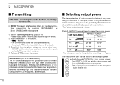
... desired. w Push and hold the microphone too close to other stations and will damage the transceiver. IMPORTANT! (for 75 W transmission): The IC-V8000 is available. The microphone can be changed while transmitting. *approx. r Release [PTT] to return to select the output power. See p....only. 5 LOW 6 Push [LOW(DUP)] several times to receive. See section at right for details. When a high SWR antenna or no antenna is connected, or when the transceiver temperature becomes extremely high, the transceiver reduces transmit output power to 25 W (approx.) automatically....
... desired. w Push and hold the microphone too close to other stations and will damage the transceiver. IMPORTANT! (for 75 W transmission): The IC-V8000 is available. The microphone can be changed while transmitting. *approx. r Release [PTT] to return to select the output power. See p....only. 5 LOW 6 Push [LOW(DUP)] several times to receive. See section at right for details. When a high SWR antenna or no antenna is connected, or when the transceiver temperature becomes extremely high, the transceiver reduces transmit output power to 25 W (approx.) automatically....
Instruction Manual
Page 82
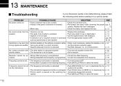
...• Volume is programmed. • Correct the offset frequency. III strong signals are audible. microphone keypad lock function. p. der the antenna connector again. • Squelch attenuator function is programmed. • Correct the subaudible tone frequency. cessed. • Wrong subaudible tone frequency... or tone squelch. p. 14 No contact possible with • The other station is low and only • Antenna feedline or the antenna connector solder • Check, and if necessary, replace the feedline or sol- 13 MAINTENANCE Troubleshooting If your transceiver seems...
...• Volume is programmed. • Correct the offset frequency. III strong signals are audible. microphone keypad lock function. p. der the antenna connector again. • Squelch attenuator function is programmed. • Correct the subaudible tone frequency. cessed. • Wrong subaudible tone frequency... or tone squelch. p. 14 No contact possible with • The other station is low and only • Antenna feedline or the antenna connector solder • Check, and if necessary, replace the feedline or sol- 13 MAINTENANCE Troubleshooting If your transceiver seems...

Instruction Manual
Page 85
speaker connector : 3-conductor 3.5 (d) mm (1⁄8″)/8 Ω †Some versions only. audio 1.0 A • Antenna connector : SO-239 (50 Ω) • Dimensions (proj. Options UT-108 DTMF DECODER UNIT HM-95/HM-118TAN/TN DTMF MICROPHONES HM-118N HAND ... OPC-440/OPC-647 MIC EXTENSION CABLES 14 OPC-441 SPEAKER EXTENSION CABLE OPC-1132/OPC-347 DC POWER CABLES OPC-589 ADAPTER CABLE CS-V8000 CLONING SOFTWARE + OPC-478 CLONING CABLE OPC-474 CLONING CABLE 74 14 SPECIFICATIONS AND OPTIONS Specifications GENERAL • Frequency coverage : (unit: MHz)...
speaker connector : 3-conductor 3.5 (d) mm (1⁄8″)/8 Ω †Some versions only. audio 1.0 A • Antenna connector : SO-239 (50 Ω) • Dimensions (proj. Options UT-108 DTMF DECODER UNIT HM-95/HM-118TAN/TN DTMF MICROPHONES HM-118N HAND ... OPC-440/OPC-647 MIC EXTENSION CABLES 14 OPC-441 SPEAKER EXTENSION CABLE OPC-1132/OPC-347 DC POWER CABLES OPC-589 ADAPTER CABLE CS-V8000 CLONING SOFTWARE + OPC-478 CLONING CABLE OPC-474 CLONING CABLE 74 14 SPECIFICATIONS AND OPTIONS Specifications GENERAL • Frequency coverage : (unit: MHz)...
