
Instruction Manual
Page 1
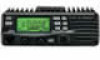
Operation is subject to the following two conditions: (1) This device may not cause harmful interference, and (2) this device must accept any interference received, including interference that may cause undesired operation. INSTRUCTION MANUAL VHF FM TRANSCEIVER iV8000 This device complies with Part 15 of the FCC rules.
Operation is subject to the following two conditions: (1) This device may not cause harmful interference, and (2) this device must accept any interference received, including interference that may cause undesired operation. INSTRUCTION MANUAL VHF FM TRANSCEIVER iV8000 This device complies with Part 15 of the FCC rules.
Instruction Manual
Page 2
The IC-V8000 VHF FM TRANSCEIVER is designed and built with Icom's superior technology and craftsmanship. With proper care, this Icom product. Many hours of research and development went into the design of your time to take a couple of moments of your IC-V8000. No risk of personal injury, ... may occur. and the logo are registered trademarks of Icom Incorporated (Japan) in - We want to thank you for the IC-V8000. Personal injury, fire hazard or electric shock may occur. SAVE THIS INSTRUCTION MANUAL- Icom, Icom Inc. many, France, Spain, Russia and/or other...
The IC-V8000 VHF FM TRANSCEIVER is designed and built with Icom's superior technology and craftsmanship. With proper care, this Icom product. Many hours of research and development went into the design of your time to take a couple of moments of your IC-V8000. No risk of personal injury, ... may occur. and the logo are registered trademarks of Icom Incorporated (Japan) in - We want to thank you for the IC-V8000. Personal injury, fire hazard or electric shock may occur. SAVE THIS INSTRUCTION MANUAL- Icom, Icom Inc. many, France, Spain, Russia and/or other...

Instruction Manual
Page 3
...with any questions regarding RF exposure and safety standards please refer to an AC outlet. ving a vehicle. NEVER connect the transceiver to play with FCC Guidelines for long periods. NEVER let objects impede the operation of chemical agents such as benzine or alcohol... Human Radio frequency Electromagnetic Fields (OET Bulletin 65) RWARNING! The transceiver will ruin the transceiver. This will become exhausted. verse polarity. DO NOT push the PTT when not actually desiring to transmit. USE Icom microphones only (supplied or optional). ufacturer's microphones have any radio ...
...with any questions regarding RF exposure and safety standards please refer to an AC outlet. ving a vehicle. NEVER connect the transceiver to play with FCC Guidelines for long periods. NEVER let objects impede the operation of chemical agents such as benzine or alcohol... Human Radio frequency Electromagnetic Fields (OET Bulletin 65) RWARNING! The transceiver will ruin the transceiver. This will become exhausted. verse polarity. DO NOT push the PTT when not actually desiring to transmit. USE Icom microphones only (supplied or optional). ufacturer's microphones have any radio ...
Instruction Manual
Page 6
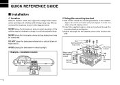
We recommend the locations shown in any way. NEVER place the transceiver where air bag deployment may be hindered or where it . Installation location D Using the mounting bracket ➀ Drill 4 holes where the mounting bracket is to ... does not interfere with driving in the diagram below. NEVER place the transceiver where normal operation of the function display. AVOID placing the transceiver in direct sunlight. • Example- DO NOT place the transceiver where hot or cold air blows directly onto it could cause bodily injury. Nut Spring washer Flat washer When...
We recommend the locations shown in any way. NEVER place the transceiver where air bag deployment may be hindered or where it . Installation location D Using the mounting bracket ➀ Drill 4 holes where the mounting bracket is to ... does not interfere with driving in the diagram below. NEVER place the transceiver where normal operation of the function display. AVOID placing the transceiver in direct sunlight. • Example- DO NOT place the transceiver where hot or cold air blows directly onto it could cause bodily injury. Nut Spring washer Flat washer When...
Instruction Manual
Page 7
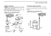
IC-V8000 to a 24 V battery. Supplied DC power cable Solder D DC power supply connection Use a 13.8 V DC power supply with at least 15 A capacity. Make sure the ... POWER SOURCE • See p. 72 for fuse replacement. QUICK REFERENCE GUIDE D Battery connection NEVER connect the transceiver directly to an AC outlet DC power supply 13.8 V −⊕ − black ⊕ red Fuses 20 A II Grommet IC-V8000 ⊕ red − black Fuses 20 A _ black + red 12 V 12 V battery NOTE: Crimp Use terminals...
IC-V8000 to a 24 V battery. Supplied DC power cable Solder D DC power supply connection Use a 13.8 V DC power supply with at least 15 A capacity. Make sure the ... POWER SOURCE • See p. 72 for fuse replacement. QUICK REFERENCE GUIDE D Battery connection NEVER connect the transceiver directly to an AC outlet DC power supply 13.8 V −⊕ − black ⊕ red Fuses 20 A II Grommet IC-V8000 ⊕ red − black Fuses 20 A _ black + red 12 V 12 V battery NOTE: Crimp Use terminals...
Instruction Manual
Page 8
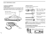
... coupling ring down. w Strip the cable as shown at left. Check with some versions of the transceiver. *HM-133V; Soft solder the center conductor. III solder solder e Slide the connector body on the front panel of the IC-V8000. QUICK REFERENCE GUIDE D Antenna installation • Antenna location To obtain maximum performance from the...
... coupling ring down. w Strip the cable as shown at left. Check with some versions of the transceiver. *HM-133V; Soft solder the center conductor. III solder solder e Slide the connector body on the front panel of the IC-V8000. QUICK REFERENCE GUIDE D Antenna installation • Antenna location To obtain maximum performance from the...
Instruction Manual
Page 9
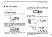
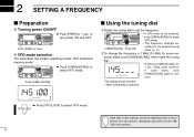
...145.3625 MHz. Tune the desired frequency The tuning dial will instruct you have purchased a brand new transceiver, some settings may want to set in 9-10 o'clock positions. Pages 9 and 11 will allow...transceiver Before powering up your first "On The Air" an enjoyable experience. 1. Resetting the CPU is necessary to 9-10 o'clock positions. We would like to take you through a few basic operation steps to make your IC-V8000... REFERENCE GUIDE Your first contact Now that you have your IC-V8000 installed in your car or shack, you may be changed from factory default. 2.
...145.3625 MHz. Tune the desired frequency The tuning dial will instruct you have purchased a brand new transceiver, some settings may want to set in 9-10 o'clock positions. Pages 9 and 11 will allow...transceiver Before powering up your first "On The Air" an enjoyable experience. 1. Resetting the CPU is necessary to 9-10 o'clock positions. We would like to take you through a few basic operation steps to make your IC-V8000... REFERENCE GUIDE Your first contact Now that you have your IC-V8000 installed in your car or shack, you may be changed from factory default. 2.
Instruction Manual
Page 16
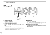
...% with a PL-259 connector and a 50 Ω coaxial cable. 5 NOTE: DO NOT use a cigarette lighter socket as a power source when operating in set mode and transceiver's temperature. (p. 61) r ANTENNA CONNECTOR [ANT] Connects a 50 Ω antenna with the supplied DC power cable. e COOLING FAN Rotates while transmitting. 1 PANEL DESCRIPTION Rear panel q e r w q SPEAKER...
...% with a PL-259 connector and a 50 Ω coaxial cable. 5 NOTE: DO NOT use a cigarette lighter socket as a power source when operating in set mode and transceiver's temperature. (p. 61) r ANTENNA CONNECTOR [ANT] Connects a 50 Ω antenna with the supplied DC power cable. e COOLING FAN Rotates while transmitting. 1 PANEL DESCRIPTION Rear panel q e r w q SPEAKER...
Instruction Manual
Page 17
... memory mode. (p. 24) ➥ Push for 1 sec. to selects memory bank condition during memory mode. (p. 32) ➥ Push for 1 sec. to select call your desired transceiver conditions. !0 BANK/OPTION SWITCH [BANK/OPTION] ➥ Push to select and toggle pager and code squelch function when the optional UT-108 is activated-DTMF...
... memory mode. (p. 24) ➥ Push for 1 sec. to selects memory bank condition during memory mode. (p. 32) ➥ Push for 1 sec. to select call your desired transceiver conditions. !0 BANK/OPTION SWITCH [BANK/OPTION] ➥ Push to select and toggle pager and code squelch function when the optional UT-108 is activated-DTMF...
Instruction Manual
Page 20
D VFO mode selection The transceiver has 2 basic operating modes: VFO mode and memory mode. ➥ Push [V/MHz(SCAN)] to turn power ON and OFF. 2 SETTING A FREQUENCY Preparation D Turning power ON/...
D VFO mode selection The transceiver has 2 basic operating modes: VFO mode and memory mode. ➥ Push [V/MHz(SCAN)] to turn power ON and OFF. 2 SETTING A FREQUENCY Preparation D Turning power ON/...
Instruction Manual
Page 23
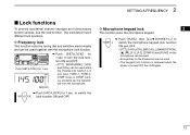
The transceiver has 2 different lock functions. Push [SET(LOCK)] for 1 sec. D Microphone keypad lock 2 This function locks the microphone keypad. ➥ Push [FUNC] then [SQLZ D(16KEY-L)] to ... ON and OFF. • [PTT], [VFO/LOCK], [MR/CALL], [BANK/OPTION], [Y], [Z], [F-1], [F-2], [DTMF-S] and [FUNC] on the microphone can be used. • All switches on the transceiver can be used together with the microphone lock function. to switch the VFO/LOCK lock function ON and OFF. Appears ➥ Push [SET(LOCK)] for...
The transceiver has 2 different lock functions. Push [SET(LOCK)] for 1 sec. D Microphone keypad lock 2 This function locks the microphone keypad. ➥ Push [FUNC] then [SQLZ D(16KEY-L)] to ... ON and OFF. • [PTT], [VFO/LOCK], [MR/CALL], [BANK/OPTION], [Y], [Z], [F-1], [F-2], [DTMF-S] and [FUNC] on the microphone can be used. • All switches on the transceiver can be used together with the microphone lock function. to switch the VFO/LOCK lock function ON and OFF. Appears ➥ Push [SET(LOCK)] for...
Instruction Manual
Page 24
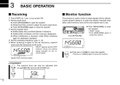
r Set the operating frequency. (pgs. 9, 10) t When receiving a signal on the set frequency, squelch opens and the transceiver emits audio. • "BUSY" appears and the S/RF indicator shows the relative signal strength for 1 sec. 3 BASIC OPERATION Receiving q Push [PWR] for the received signal. ...
r Set the operating frequency. (pgs. 9, 10) t When receiving a signal on the set frequency, squelch opens and the transceiver emits audio. • "BUSY" appears and the S/RF indicator shows the relative signal strength for 1 sec. 3 BASIC OPERATION Receiving q Push [PWR] for the received signal. ...
Instruction Manual
Page 25
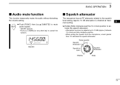
Approx. 10 dB attenuation is open. Appears Squelch attenuator The transceiver has an RF attenuator related to 10 dB (approx.) between 12 o'clock and fully clockwise position. • When setting the squelch from the microphone, a level ...
Approx. 10 dB attenuation is open. Appears Squelch attenuator The transceiver has an RF attenuator related to 10 dB (approx.) between 12 o'clock and fully clockwise position. • When setting the squelch from the microphone, a level ...
Instruction Manual
Page 26
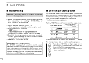
...-distance communications may distort the signal. and 4 [LOW 6(DTMF)] for 75 W transmission): The IC-V8000 is equipped with protection circuit to select the output power. w Push and hold the microphone too close to other stations and will damage the transceiver. This may reduce the possibility of interference to your operating requirements. Low output...
...-distance communications may distort the signal. and 4 [LOW 6(DTMF)] for 75 W transmission): The IC-V8000 is equipped with protection circuit to select the output power. w Push and hold the microphone too close to other stations and will damage the transceiver. This may reduce the possibility of interference to your operating requirements. Low output...
Instruction Manual
Page 27
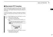
.... ceive. • Two beeps sound when transmission is started and a long beep sounds when returning to re- See p. 63 for details. Using this function, the transceiver has a time-out timer. BASIC OPERATION 3 3 16 To prevent accidental, continuous transmissions with the one -touch PTT switch (each push switches between transmit/receive). One...
.... ceive. • Two beeps sound when transmission is started and a long beep sounds when returning to re- See p. 63 for details. Using this function, the transceiver has a time-out timer. BASIC OPERATION 3 3 16 To prevent accidental, continuous transmissions with the one -touch PTT switch (each push switches between transmit/receive). One...
Instruction Manual
Page 31
... 100 MHz digit, cancel the DTMF memory encoder in advance. (p. 46) • Push [DTMF-S] again to return the keypad to normal function control. • The transceiver has 10 DTMF memory channels for 0.5 sec.; Push , then or . 20 D 1750 Hz tone The microphone has 1750 Hz tone capability, used for ring tone...
... 100 MHz digit, cancel the DTMF memory encoder in advance. (p. 46) • Push [DTMF-S] again to return the keypad to normal function control. • The transceiver has 10 DTMF memory channels for 0.5 sec.; Push , then or . 20 D 1750 Hz tone The microphone has 1750 Hz tone capability, used for ring tone...
Instruction Manual
Page 32
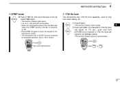
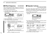
...)] e Rotate the tuning dial to other stations by the offset frequency. r Push [TONE(T-SCAN)] to enter set mode. 21 Repeater lockout function is received. The transceiver has two inhibiting conditions, repeater and busy. r Rotate the tuning dial to turn the repeater lockout function to turn power ON. ble. w Push [SET(LOCK...
...)] e Rotate the tuning dial to other stations by the offset frequency. r Push [TONE(T-SCAN)] to enter set mode. 21 Repeater lockout function is received. The transceiver has two inhibiting conditions, repeater and busy. r Rotate the tuning dial to turn the repeater lockout function to turn power ON. ble. w Push [SET(LOCK...
Instruction Manual
Page 35
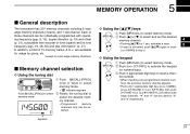
... channels. Appears D Using the [Y]/[Z] keys z Push [MR/CALL] to J, are available for usage by group, etc. *except for numeral input. 5 MEMORY OPERATION General description The transceiver has 207 memory channels including 6 scan edge memory channels (3 pairs), and 1 call channel. In addition, a total of these channels can be individually programmed with operating...
... channels. Appears D Using the [Y]/[Z] keys z Push [MR/CALL] to J, are available for usage by group, etc. *except for numeral input. 5 MEMORY OPERATION General description The transceiver has 207 memory channels including 6 scan edge memory channels (3 pairs), and 1 call channel. In addition, a total of these channels can be individually programmed with operating...
Instruction Manual
Page 54
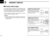
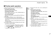
...43 VFO frequency 50 msec. See previous page for a signal on the selected memory VFO channel every 5 sec. frequency 50 msec. The transceiver has 3 priority watch types to the selected scan resume condition. NOTES: ➧ If the pocket beep function is useful to speed up ...on a VFO frequency, priority watch checks for signals on each memory channel in sequence. • The memory skip function is activated, the transceiver automatically selects the tone squelch function when priority watch starts. You can transmit on a VFO fre- 5 sec. 8 PRIORITY WATCH Priority ...
...43 VFO frequency 50 msec. See previous page for a signal on the selected memory VFO channel every 5 sec. frequency 50 msec. The transceiver has 3 priority watch types to the selected scan resume condition. NOTES: ➧ If the pocket beep function is useful to speed up ...on a VFO frequency, priority watch checks for signals on each memory channel in sequence. • The memory skip function is activated, the transceiver automatically selects the tone squelch function when priority watch starts. You can transmit on a VFO fre- 5 sec. 8 PRIORITY WATCH Priority ...
Instruction Manual
Page 55
... [V/MHz(SCAN)] for 1 sec. For memory scan watch: Push [MR/CALL], then push [SCAN 2] to start the watch. • The transceiver checks the memory or call channel watch resumes according to the selected scan resume con- to start the watch . w Set the watching channel(s). While... pausing or receiving a signal on the memory or call channel. v To stop the watch . • The transceiver checks the memory or call channel by pushing [M/CALL(PRIO)] several times. r Push [M/CALL(PRIO)] while the display shows the mem- c Push [PRIO ...
... [V/MHz(SCAN)] for 1 sec. For memory scan watch: Push [MR/CALL], then push [SCAN 2] to start the watch. • The transceiver checks the memory or call channel watch resumes according to the selected scan resume con- to start the watch . w Set the watching channel(s). While... pausing or receiving a signal on the memory or call channel. v To stop the watch . • The transceiver checks the memory or call channel by pushing [M/CALL(PRIO)] several times. r Push [M/CALL(PRIO)] while the display shows the mem- c Push [PRIO ...