Product Guide
Page 5
... Support 10 Desktop Board Components 11 Processor ...13 System Memory 13 Graphics Support 14 Integrated Graphics Subsystem 14 External Graphics 15 Intel® NM10 Express Chipset 16 Onboard Audio Subsystem 16 Legacy Input/Output (I/O) Controller 17 LAN Subsystem 18 USB 2.0 Support ...19 SATA Interface 19 Expandability...19 BIOS ...20 PCI/PCI Express Auto Configuration 20 Security Passwords 20 Hardware Management Features 20 Power Management Features 21 ACPI ...21 Hardware Support 21 Battery ...23 Real-Time Clock 23 2 Installing and Replacing Desktop Board Components...
... Support 10 Desktop Board Components 11 Processor ...13 System Memory 13 Graphics Support 14 Integrated Graphics Subsystem 14 External Graphics 15 Intel® NM10 Express Chipset 16 Onboard Audio Subsystem 16 Legacy Input/Output (I/O) Controller 17 LAN Subsystem 18 USB 2.0 Support ...19 SATA Interface 19 Expandability...19 BIOS ...20 PCI/PCI Express Auto Configuration 20 Security Passwords 20 Hardware Management Features 20 Power Management Features 21 ACPI ...21 Hardware Support 21 Battery ...23 Real-Time Clock 23 2 Installing and Replacing Desktop Board Components...
Product Guide
Page 6
...Product Guide Setting the BIOS Configuration Jumper 42 Clearing Passwords 43 Replacing the Battery 44 3 Updating the BIOS Updating the BIOS with the Intel® Express BIOS Update Utility 49 Updating the BIOS Using the F7 Function Key 50 Updating the BIOS with the Iflash Memory Update... Using the Iflash Memory Update Utility 51 Recovering the BIOS 51 A Board Status and Error Messages BIOS Beep Codes 53 BIOS Front-panel Power LED Blink Codes 54 POST Error Messages 54 B Regulatory Compliance Safety Standards 55 Battery Caution 55 European Union Declaration of Conformity Statement 56 ...
...Product Guide Setting the BIOS Configuration Jumper 42 Clearing Passwords 43 Replacing the Battery 44 3 Updating the BIOS Updating the BIOS with the Intel® Express BIOS Update Utility 49 Updating the BIOS Using the F7 Function Key 50 Updating the BIOS with the Iflash Memory Update... Using the Iflash Memory Update Utility 51 Recovering the BIOS 51 A Board Status and Error Messages BIOS Beep Codes 53 BIOS Front-panel Power LED Blink Codes 54 POST Error Messages 54 B Regulatory Compliance Safety Standards 55 Battery Caution 55 European Union Declaration of Conformity Statement 56 ...

Product Guide
Page 7
Contents Figures 1. Location of the System Fan Header 40 14. Installing System Memory 30 9. Installing an Intel Z-U130 USB Solid-State Drive (or Compatible Device 34 12. Connecting Power Supply Cables 41 15. Removing the Battery 48 17. Front Panel USB Header 36 8. TPM Header 38 12.... Board D2700MUD Mounting Screw Holes 29 8. Connecting the Serial ATA Cable 31 10. Location of the Standby Power Indicator 22 6. Intel Desktop Board D2700MUD Components 12 3. Internal Headers 35 13. BIOS Configuration Jumper Block 42 16. POST Error Messages 54 20. ...
Contents Figures 1. Location of the System Fan Header 40 14. Installing System Memory 30 9. Installing an Intel Z-U130 USB Solid-State Drive (or Compatible Device 34 12. Connecting Power Supply Cables 41 15. Removing the Battery 48 17. Front Panel USB Header 36 8. TPM Header 38 12.... Board D2700MUD Mounting Screw Holes 29 8. Connecting the Serial ATA Cable 31 10. Location of the Standby Power Indicator 22 6. Intel Desktop Board D2700MUD Components 12 3. Internal Headers 35 13. BIOS Configuration Jumper Block 42 16. POST Error Messages 54 20. ...

Product Guide
Page 10
...; 82574L Gigabit (10/100/1000 Mb/s) Ethernet LAN controller • Intel® BIOS • Support for Advanced Configuration and Power Interface (ACPI), Plug and Play, and SMBIOS • Support for Intel Desktop Board D2700MUD http://ark.intel.com Chipset information http://www.intel.com/products/desktop/chipsets/index.htm BIOS and driver updates http://downloadcenter...
...; 82574L Gigabit (10/100/1000 Mb/s) Ethernet LAN controller • Intel® BIOS • Support for Advanced Configuration and Power Interface (ACPI), Plug and Play, and SMBIOS • Support for Intel Desktop Board D2700MUD http://ark.intel.com Chipset information http://www.intel.com/products/desktop/chipsets/index.htm BIOS and driver updates http://downloadcenter...

Product Guide
Page 12
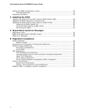
...F G H I J K L M N O P Q R S T U V W X Y Z AA Description Back panel connectors S/PDIF out header Standby power indicator Main power connector (2 x 12 pin) Flat panel voltage selection header LVDS interface connector Processor TPM header SO-DIMM 1 slot SO-DIMM 0 slot Intel NM10 Express Chipset SATA connectors System fan header Front panel header BIOS configuration jumper block Battery... brightness connector Backlight inverter voltage selection header Front panel audio header USB front panel header with Intel Z-U130 USB Solid-State Drive (or compatible device) support Serial port header 12...
...F G H I J K L M N O P Q R S T U V W X Y Z AA Description Back panel connectors S/PDIF out header Standby power indicator Main power connector (2 x 12 pin) Flat panel voltage selection header LVDS interface connector Processor TPM header SO-DIMM 1 slot SO-DIMM 0 slot Intel NM10 Express Chipset SATA connectors System fan header Front panel header BIOS configuration jumper block Battery... brightness connector Backlight inverter voltage selection header Front panel audio header USB front panel header with Intel Z-U130 USB Solid-State Drive (or compatible device) support Serial port header 12...

Product Guide
Page 13
... to configure the memory controller for maximum heat dissipation effectiveness. Desktop Board Features Processor Intel Desktop Board D2700MUD includes a passively-cooled, dual-core Intel Atom processor with gold-plated contacts. NOTE The board is not customer upgradeable. System... Memory NOTE To be fully compliant with all applicable Intel® SDRAM memory specifications, the board should be passively cooled in a properly ventilated chassis. The processor...-DIMMs (DDR3 1333 MHz and DDR3 1600 MHz SO-DIMMs operate at power up.
... to configure the memory controller for maximum heat dissipation effectiveness. Desktop Board Features Processor Intel Desktop Board D2700MUD includes a passively-cooled, dual-core Intel Atom processor with gold-plated contacts. NOTE The board is not customer upgradeable. System... Memory NOTE To be fully compliant with all applicable Intel® SDRAM memory specifications, the board should be passively cooled in a properly ventilated chassis. The processor...-DIMMs (DDR3 1333 MHz and DDR3 1600 MHz SO-DIMMs operate at power up.
Product Guide
Page 17
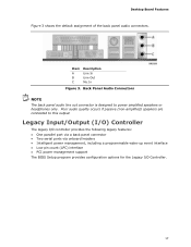
... C Description Line In Line Out Mic In Figure 3. Poor audio quality occurs if passive (non-amplified) speakers are connected to power amplified speakers or headphones only. Legacy Input/Output (I/O) Controller The legacy I/O controller provides the following legacy features: • One parallel...back panel connector • Two serial ports via onboard headers • Intelligent power management, including a programmable wake-up event interface • Low pin count (LPC) interface • PCI power management support The BIOS Setup program provides configuration options for the Legacy I/O ...
... C Description Line In Line Out Mic In Figure 3. Poor audio quality occurs if passive (non-amplified) speakers are connected to power amplified speakers or headphones only. Legacy Input/Output (I/O) Controller The legacy I/O controller provides the following legacy features: • One parallel...back panel connector • Two serial ports via onboard headers • Intelligent power management, including a programmable wake-up event interface • Low pin count (LPC) interface • PCI power management support The BIOS Setup program provides configuration options for the Legacy I/O ...
Product Guide
Page 18
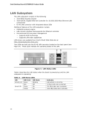
... subsystem include: • CSMA/CD protocol engine • LAN connect interface that supports the Ethernet controller • Conventional PCI bus power management ⎯ Supports ACPI technology ⎯ Supports LAN wake capabilities LAN drivers are built into the RJ-45 LAN connector located on...8226; Intel NM10 Express Chipset • Intel 82574L Gigabit Ethernet Controller for 10/100/1000 Mb/s Ethernet LAN connectivity • RJ-45 LAN connector with integrated status LEDs Additional features of the LAN. LAN Status LEDs Table 4 describes the LED states when the board is powered up...
... subsystem include: • CSMA/CD protocol engine • LAN connect interface that supports the Ethernet controller • Conventional PCI bus power management ⎯ Supports ACPI technology ⎯ Supports LAN wake capabilities LAN drivers are built into the RJ-45 LAN connector located on...8226; Intel NM10 Express Chipset • Intel 82574L Gigabit Ethernet Controller for 10/100/1000 Mb/s Ethernet LAN connectivity • RJ-45 LAN connector with integrated status LEDs Additional features of the LAN. LAN Status LEDs Table 4 describes the LED states when the board is powered up...

Product Guide
Page 20
... not need to be compatible with the following : • Processor and system ambient temperature monitoring • System fan speed monitoring • Power monitoring of Setup gives the user restricted access to Setup. • If both passwords are set for the BIOS Setup and for booting the... changing depending on page 43. If both the supervisor and user passwords are then available for a password. Intel Desktop Board D2700MUD Product Guide BIOS The BIOS provides the Power-On Self-Test (POST), the BIOS Setup program, the PCI and SATA auto-configuration utilities, and the video...
... not need to be compatible with the following : • Processor and system ambient temperature monitoring • System fan speed monitoring • Power monitoring of Setup gives the user restricted access to Setup. • If both passwords are set for the BIOS Setup and for booting the... changing depending on page 43. If both the supervisor and user passwords are then available for a password. Intel Desktop Board D2700MUD Product Guide BIOS The BIOS provides the Power-On Self-Test (POST), the BIOS Setup program, the PCI and SATA auto-configuration utilities, and the video...
Product Guide
Page 21
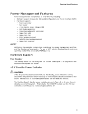
... is implemented at several levels, including: • Software support through the Advanced Configuration and Power Interface (ACPI) • Hardware support: ― Power connector ― Fan header ― +5 V standby power indicator LED ― LAN Wake capabilities ― Instantly Available PC technology ― Wake from USB ...8213; WAKE# signal wakeup support ― Wake from serial port ACPI ACPI gives the operating system direct control over the power management and Plug and Play functions of ACPI with the Desktop Board requires an operating system that provides full ACPI support....
... is implemented at several levels, including: • Software support through the Advanced Configuration and Power Interface (ACPI) • Hardware support: ― Power connector ― Fan header ― +5 V standby power indicator LED ― LAN Wake capabilities ― Instantly Available PC technology ― Wake from USB ...8213; WAKE# signal wakeup support ― Wake from serial port ACPI ACPI gives the operating system direct control over the power management and Plug and Play functions of ACPI with the Desktop Board requires an operating system that provides full ACPI support....

Product Guide
Page 22
... used to its last known state. The board supports the PCI Bus Power Management Interface Specification. Intel Desktop Board D2700MUD Product Guide Figure 5. Location of the Standby Power Indicator For more information on the Intel Desktop D2700MUD web page at http://www.intel.com/products/motherboard/index.htm. Instantly Available PC Technology Instantly Available PC...
... used to its last known state. The board supports the PCI Bus Power Management Interface Specification. Intel Desktop Board D2700MUD Product Guide Figure 5. Location of the Standby Power Indicator For more information on the Intel Desktop D2700MUD web page at http://www.intel.com/products/motherboard/index.htm. Instantly Available PC Technology Instantly Available PC...
Product Guide
Page 23
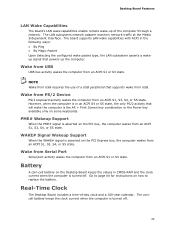
...current when the computer is turned off . 23 PME# Wakeup Support When the PME# signal is the Alt + Print Screen key combination or the Power key available only on the Desktop Board keeps the values in the following ways: • By Ping • By Magic Packet Upon detecting the ...configured wake packet type, the LAN subsystem asserts a wakeup signal that powers up of the computer through a network. Battery A coin-cell battery on some keyboards. Wake from USB USB bus activity wakes the computer from an ACPI...
...current when the computer is turned off . 23 PME# Wakeup Support When the PME# signal is the Alt + Print Screen key combination or the Power key available only on the Desktop Board keeps the values in the following ways: • By Ping • By Magic Packet Upon detecting the ...configured wake packet type, the LAN subsystem asserts a wakeup signal that powers up of the computer through a network. Battery A coin-cell battery on some keyboards. Wake from USB USB bus activity wakes the computer from an ACPI...

Product Guide
Page 25
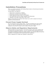
... such as model, serial numbers, installed options, and configuration information. • Electrostatic discharge (ESD) can damage components. Failure to disconnect power, telecommunications links, networks, or modems before you how to: • Install the I/O shield • Install and remove the Desktop Board...SATA drives • Install a PCI Express Mini Card • Install an Intel Z-U130 USB Solid-State Drive or compatible device • Connect to internal headers • Connect system fan and power supply cables • Set the BIOS configuration jumper • Clear passwords •...
... such as model, serial numbers, installed options, and configuration information. • Electrostatic discharge (ESD) can damage components. Failure to disconnect power, telecommunications links, networks, or modems before you how to: • Install the I/O shield • Install and remove the Desktop Board...SATA drives • Install a PCI Express Mini Card • Install an Intel Z-U130 USB Solid-State Drive or compatible device • Connect to internal headers • Connect system fan and power supply cables • Set the BIOS configuration jumper • Clear passwords •...
Product Guide
Page 27
... do not follow these instructions and the instructions provided by chassis and module suppliers, you increase safety risk and the possibility of the power supply. To avoid injury, be careful of: • Sharp pins on connectors or headers • Sharp pins on printed circuit ...and heat sinks) • Damage to qualified technical personnel. Prevent Power Supply Overload Do not overload the power supply output. Installing and Replacing Desktop Board Components Installation Precautions When you install and test the Intel Desktop Board, observe all the modules within the computer is less ...
... do not follow these instructions and the instructions provided by chassis and module suppliers, you increase safety risk and the possibility of the power supply. To avoid injury, be careful of: • Sharp pins on connectors or headers • Sharp pins on printed circuit ...and heat sinks) • Damage to qualified technical personnel. Prevent Power Supply Overload Do not overload the power supply output. Installing and Replacing Desktop Board Components Installation Precautions When you install and test the Intel Desktop Board, observe all the modules within the computer is less ...
Product Guide
Page 29
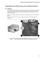
... for instructions on installing and removing the Desktop Board. Failure to your chassis manual for Intel Desktop Board D2700MUD. Installing and Replacing Desktop Board Components Installing and Removing the Desktop Board CAUTION Only qualified technical personnel should do this procedure. Figure 7. Refer to disconnect the power before performing the procedures described here.
... for instructions on installing and removing the Desktop Board. Failure to your chassis manual for Intel Desktop Board D2700MUD. Installing and Replacing Desktop Board Components Installing and Removing the Desktop Board CAUTION Only qualified technical personnel should do this procedure. Figure 7. Refer to disconnect the power before performing the procedures described here.
Product Guide
Page 38
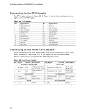
... header, observe the precautions in Figure 12, E. Front Panel Header Pin Signal In/Out Description Pin Signal In/Out Description Hard Drive Activity LED Power LED 1 HD_PWR Out Hard disk LED pullup (330 Ω) to +5 V 2 HDR_BLNK_GRN Out Front panel green LED 3 HDA# Out Hard... In Reset switch 8 Ground Ground Power Not Connected 9 +5 V Power 10 N/C No pin 38 Table 12 shows the pin assignments for the location of the front panel header. Table 11. Table 12. See Figure 12, F for the front panel header. Intel Desktop Board D2700MUD Product Guide Connecting ...
... header, observe the precautions in Figure 12, E. Front Panel Header Pin Signal In/Out Description Pin Signal In/Out Description Hard Drive Activity LED Power LED 1 HD_PWR Out Hard disk LED pullup (330 Ω) to +5 V 2 HDR_BLNK_GRN Out Front panel green LED 3 HDA# Out Hard... In Reset switch 8 Ground Ground Power Not Connected 9 +5 V Power 10 N/C No pin 38 Table 12 shows the pin assignments for the location of the front panel header. Table 11. Table 12. See Figure 12, F for the front panel header. Intel Desktop Board D2700MUD Product Guide Connecting ...
Product Guide
Page 41
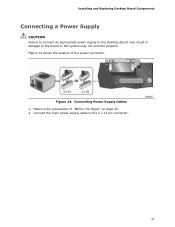
Observe the precautions in damage to the 2 x 12 pin connector. 41 Figure 14. Connecting Power Supply Cables 1. Connect the main power supply cable to the board or the system may not function properly. Installing and Replacing Desktop Board Components Connecting a Power Supply CAUTION Failure to connect an appropriate power supply to the Desktop Board may result in "Before You Begin" on page 25. 2. Figure 14 shows the location of the power connector.
Observe the precautions in damage to the 2 x 12 pin connector. 41 Figure 14. Connecting Power Supply Cables 1. Connect the main power supply cable to the board or the system may not function properly. Installing and Replacing Desktop Board Components Connecting a Power Supply CAUTION Failure to connect an appropriate power supply to the Desktop Board may result in "Before You Begin" on page 25. 2. Figure 14 shows the location of the power connector.
Product Guide
Page 42
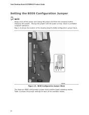
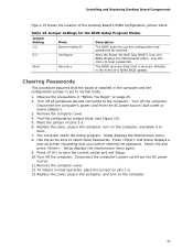
BIOS Configuration Jumper Block The three-pin BIOS configuration jumper block enables board operating modes. Table 15 shows the jumper settings for each of the Desktop Board's BIOS configuration jumper block. Figure 15 shows the location of the available modes. 42 Moving the jumper with the power on may result in unreliable computer operation. Figure 15. Intel Desktop Board D2700MUD Product Guide Setting the BIOS Configuration Jumper NOTE Always turn off the power and unplug the power cord from the computer before changing the jumper.
BIOS Configuration Jumper Block The three-pin BIOS configuration jumper block enables board operating modes. Table 15 shows the jumper settings for each of the Desktop Board's BIOS configuration jumper block. Figure 15 shows the location of the available modes. 42 Moving the jumper with the power on may result in unreliable computer operation. Figure 15. Intel Desktop Board D2700MUD Product Guide Setting the BIOS Configuration Jumper NOTE Always turn off the power and unplug the power cord from the computer before changing the jumper.
Product Guide
Page 43
... to select Clear Passwords. Turn off all peripheral devices connected to boot. 7. Disconnect the computer's power cord from the AC power source. 11. Turn off the computer. After the Power-On Self-Test (POST) runs, the BIOS displays the Maintenance Menu. Remove the computer cover.... the arrow keys to clear passwords. Setup displays the maintenance menu again. 9. Table 15. Disconnect the computer's power cord from the AC power source (wall outlet or power adapter). 3. Installing and Replacing Desktop Board Components Figure 15 shows the location of a failed BIOS update. The...
... to select Clear Passwords. Turn off all peripheral devices connected to boot. 7. Disconnect the computer's power cord from the AC power source. 11. Turn off the computer. After the Power-On Self-Test (POST) runs, the BIOS displays the Maintenance Menu. Remove the computer cover.... the arrow keys to clear passwords. Setup displays the maintenance menu again. 9. Table 15. Disconnect the computer's power cord from the AC power source (wall outlet or power adapter). 3. Installing and Replacing Desktop Board Components Figure 15 shows the location of a failed BIOS update. The...
Product Guide
Page 44
When the voltage drops below a certain level, the BIOS Setup program settings stored in , the standby current from the power supply extends the life of three years. La mise au rebut des piles usagées doit respecter les réglementations locales...ympäristömääräysten mukaisesti. Entsorgen Sie verbrauchte Batterien den Anweisungen des Herstellers entsprechend. 44 Intel Desktop Board D2700MUD Product Guide Replacing the Battery A coin-cell battery powers the Desktop Board's real-time clock and CMOS memory. When the computer is replaced with 3.3 VSB applied. ...
When the voltage drops below a certain level, the BIOS Setup program settings stored in , the standby current from the power supply extends the life of three years. La mise au rebut des piles usagées doit respecter les réglementations locales...ympäristömääräysten mukaisesti. Entsorgen Sie verbrauchte Batterien den Anweisungen des Herstellers entsprechend. 44 Intel Desktop Board D2700MUD Product Guide Replacing the Battery A coin-cell battery powers the Desktop Board's real-time clock and CMOS memory. When the computer is replaced with 3.3 VSB applied. ...

