
Product Specification
Page 5
... Block Diagram 15 1.2 Online Support ...16 1.3 Operating System Support 16 1.4 Design Specifications 17 1.5 Processor ...20 1.6 System Memory ...21 1.6.1 Memory Configurations 23 1.7 Intel® 865GV Chipset 25 1.7.1 Intel 865GV Graphics Subsystem 26 1.7.2 USB...34 1.7.3 IDE Support 34 1.7.4 Real-Time Clock, CMOS SRAM,... Audio Subsystem...38 1.9.1 Audio Subsystem Software 38 1.9.2 Audio Connectors 38 1.9.3 Realtek ALC202A-based Audio Subsystem (Optional 39 1.9.4 Intel® Flex 6 Audio Subsystem (Optional 39 1.10 LAN Subsystem...41 1.10.1 10/100 Mbits/sec LAN Subsystem (Optional...
... Block Diagram 15 1.2 Online Support ...16 1.3 Operating System Support 16 1.4 Design Specifications 17 1.5 Processor ...20 1.6 System Memory ...21 1.6.1 Memory Configurations 23 1.7 Intel® 865GV Chipset 25 1.7.1 Intel 865GV Graphics Subsystem 26 1.7.2 USB...34 1.7.3 IDE Support 34 1.7.4 Real-Time Clock, CMOS SRAM,... Audio Subsystem...38 1.9.1 Audio Subsystem Software 38 1.9.2 Audio Connectors 38 1.9.3 Realtek ALC202A-based Audio Subsystem (Optional 39 1.9.4 Intel® Flex 6 Audio Subsystem (Optional 39 1.10 LAN Subsystem...41 1.10.1 10/100 Mbits/sec LAN Subsystem (Optional...

Product Specification
Page 11
1 Product Description What This Chapter Contains 1.1 Overview ...12 1.2 Online Support ...16 1.3 Operating System Support 16 1.4 Design Specifications 17 1.5 Processor ...20 1.6 System Memory ...21 1.7 Intel® 865GV Chipset 25 1.8 I/O Controller ...36 1.9 Audio Subsystem...38 1.10 LAN Subsystem...41 1.11 Hardware Management Subsystem 43 1.12 Power Management 45 11
1 Product Description What This Chapter Contains 1.1 Overview ...12 1.2 Online Support ...16 1.3 Operating System Support 16 1.4 Design Specifications 17 1.5 Processor ...20 1.6 System Memory ...21 1.7 Intel® 865GV Chipset 25 1.8 I/O Controller ...36 1.9 Audio Subsystem...38 1.10 LAN Subsystem...41 1.11 Hardware Management Subsystem 43 1.12 Power Management 45 11
Product Specification
Page 12
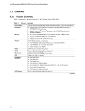
...[243.84 millimeters by 215.90 millimeters]) • Support for an Intel® Pentium® 4 processor in an mPGA478 socket with a 400/533/800 MHz system bus • Support for an Intel® Celeron® processor in an mPGA478 socket with a 400 MHz system bus • Two ...diskette drive interface • PS/2* keyboard and mouse ports Refer to 2 GB of system memory Intel® 865GV Chipset, consisting of the Desktop Board D865GVHZ. Table 1. Feature Summary Form Factor Processor Memory Chipset Video Audio I /O controller Support for up to Manufacturing Options on page 13 continued...
...[243.84 millimeters by 215.90 millimeters]) • Support for an Intel® Pentium® 4 processor in an mPGA478 socket with a 400/533/800 MHz system bus • Support for an Intel® Celeron® processor in an mPGA478 socket with a 400 MHz system bus • Two ...diskette drive interface • PS/2* keyboard and mouse ports Refer to 2 GB of system memory Intel® 865GV Chipset, consisting of the Desktop Board D865GVHZ. Table 1. Feature Summary Form Factor Processor Memory Chipset Video Audio I /O controller Support for up to Manufacturing Options on page 13 continued...

Product Specification
Page 15
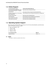
... or socket Parallel ATA IDE Connectors (2) Parallel ATA IDE Interface mPGA478 System Bus Processor Socket (400/533/800 MHz) LAN Connector Gigabit LAN PLC (Optional) CSA Interface Display Interface VGA Port Intel 82865GV Graphics and Memory Controller Hub (GMCH) AHA Bus Channel A/B DIMM Sockets ...Bus Back Panel/ Front Panel USB Ports Serial Port Parallel Port PS/2 Mouse PS/2 Keyboard Diskette Drive Connector Intel 82801EB I/O Controller Hub (ICH5) 4 Mbit Firmware Hub (FWH) Intel 865GV Chipset CSMA/CD Unit Interface 10/100 LAN PLC (Optional) LAN Connector PCI Slot 1 PCI Slot ...
... or socket Parallel ATA IDE Connectors (2) Parallel ATA IDE Interface mPGA478 System Bus Processor Socket (400/533/800 MHz) LAN Connector Gigabit LAN PLC (Optional) CSA Interface Display Interface VGA Port Intel 82865GV Graphics and Memory Controller Hub (GMCH) AHA Bus Channel A/B DIMM Sockets ...Bus Back Panel/ Front Panel USB Ports Serial Port Parallel Port PS/2 Mouse PS/2 Keyboard Diskette Drive Connector Intel 82801EB I/O Controller Hub (ICH5) 4 Mbit Firmware Hub (FWH) Intel 865GV Chipset CSMA/CD Unit Interface 10/100 LAN PLC (Optional) LAN Connector PCI Slot 1 PCI Slot ...
Product Specification
Page 16
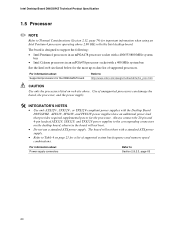
... about Supported drivers Refer to Section 1.2 ✏ NOTE Third party vendors may offer other drivers. 16 Intel Desktop Board D865GVHZ under "Desktop Board Products" or "Desktop Board Support" Available configurations for the Desktop Board D865GVHZ Processor data sheets ICH5 addressing Audio software and utilities LAN software and drivers Visit this World Wide...
... about Supported drivers Refer to Section 1.2 ✏ NOTE Third party vendors may offer other drivers. 16 Intel Desktop Board D865GVHZ under "Desktop Board Products" or "Desktop Board Support" Available configurations for the Desktop Board D865GVHZ Processor data sheets ICH5 addressing Audio software and utilities LAN software and drivers Visit this World Wide...
Product Specification
Page 20
... of supported system bus frequency and memory speed combinations. For information about Supported processors for the processor. Intel Desktop Board D865GVHZ Technical Product Specification 1.5 Processor ✏ NOTE Refer to Thermal Considerations (Section 2.12, page 79) for important information when using an Intel Pentium 4 processor operating above . For information about Power supply connectors Refer to http://www...
... of supported system bus frequency and memory speed combinations. For information about Supported processors for the processor. Intel Desktop Board D865GVHZ Technical Product Specification 1.5 Processor ✏ NOTE Refer to Thermal Considerations (Section 2.12, page 79) for important information when using an Intel Pentium 4 processor operating above . For information about Power supply connectors Refer to http://www...
Product Specification
Page 21
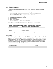
... Detect • DDR400, DDR333, and DDR266 SDRAM DIMMs Table 4 lists the supported system bus frequency and memory speed combinations. DDR400 DDR333 (Note) DDR266 The processor's system bus frequency must be impacted or the DIMMs may be ... 800 MHz 800 or 533 MHz 800, 533, or 400 MHz Note: When using... an 800 MHz system bus frequency processor, DDR333 memory is installed, the BIOS will attempt to accurately configure memory settings for optimum performance. Table 4. This allows the BIOS to read the ...
... Detect • DDR400, DDR333, and DDR266 SDRAM DIMMs Table 4 lists the supported system bus frequency and memory speed combinations. DDR400 DDR333 (Note) DDR266 The processor's system bus frequency must be impacted or the DIMMs may be ... 800 MHz 800 or 533 MHz 800, 533, or 400 MHz Note: When using... an 800 MHz system bus frequency processor, DDR333 memory is installed, the BIOS will attempt to accurately configure memory settings for optimum performance. Table 4. This allows the BIOS to read the ...
Product Specification
Page 33
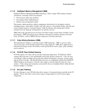
... shifted viewing allows the user to view and digitally record video pictures on their PC. The Intel Pentium 4 processor in texture loads, 2D blitters, color/Z, MPEG2 motion compression, and other operations. 1.7.1.7 Video Mixing Renderer (VMR) The Intel Extreme Graphics 2 controller features VMR technology. Product Description 1.7.1.6 Intelligent Memory Management (IMM) Intelligent Memory Management (IMM...
... shifted viewing allows the user to view and digitally record video pictures on their PC. The Intel Pentium 4 processor in texture loads, 2D blitters, color/Z, MPEG2 motion compression, and other operations. 1.7.1.7 Video Mixing Renderer (VMR) The Intel Extreme Graphics 2 controller features VMR technology. Product Description 1.7.1.6 Intelligent Memory Management (IMM) Intelligent Memory Management (IMM...

Product Specification
Page 34
... to reduce reflections, noise, and inductive coupling. 34 The Parallel ATA IDE interfaces support the following modes: • Programmed I/O (PIO): processor controls data transfer. • 8237-style DMA: DMA offloads the processor, supporting transfer rates of up to 16 MB/sec. • Ultra DMA: DMA protocol on IDE bus supporting host and.../sec. • ATA-66: DMA protocol on the back panel The location of up to eight USB 2.0 ports, supports UHCI and EHCI, and uses UHCI- Intel Desktop Board D865GVHZ Technical Product Specification 1.7.2 USB The board supports up to 66 MB/sec.
... to reduce reflections, noise, and inductive coupling. 34 The Parallel ATA IDE interfaces support the following modes: • Programmed I/O (PIO): processor controls data transfer. • 8237-style DMA: DMA offloads the processor, supporting transfer rates of up to 16 MB/sec. • Ultra DMA: DMA protocol on IDE bus supporting host and.../sec. • ATA-66: DMA protocol on the back panel The location of up to eight USB 2.0 ports, supports UHCI and EHCI, and uses UHCI- Intel Desktop Board D865GVHZ Technical Product Specification 1.7.2 USB The board supports up to 66 MB/sec.
Product Specification
Page 44
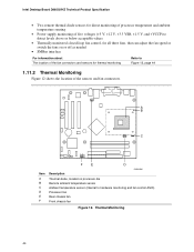
Thermal Monitoring 44 Intel Desktop Board D865GVHZ Technical Product Specification • Two remote thermal diode sensors for direct monitoring of processor temperature and ambient temperature sensing • Power supply monitoring of five voltages (+5 V, +12 V, +3.3 VSB, +1.5 V, and +VCCP) to detect levels above... shows the location of the sensors and fan connectors. 13 A B 31 C 13 Item A B C D E F F E D OM16405 Description Thermal diode, located on processor die Remote ambient temperature sensor Ambient temperature sensor (internal to hardware monitoring and fan control ASIC...
Thermal Monitoring 44 Intel Desktop Board D865GVHZ Technical Product Specification • Two remote thermal diode sensors for direct monitoring of processor temperature and ambient temperature sensing • Power supply monitoring of five voltages (+5 V, +12 V, +3.3 VSB, +1.5 V, and +VCCP) to detect levels above... shows the location of the sensors and fan connectors. 13 A B 31 C 13 Item A B C D E F F E D OM16405 Description Thermal diode, located on processor die Remote ambient temperature sensor Ambient temperature sensor (internal to hardware monitoring and fan control ASIC...
Product Specification
Page 46
Intel Desktop Board D865GVHZ Technical Product Specification Table 14... state transitions. Soft off) For information about The Desktop Boards' compliance level with ACPI Refer to put the system as a whole into a low-power state. Processor stopped G1 - working state) Soft-off (ACPI G2/G5 - Soft off . Targeted System Power (Note 1) Full power > 30 W 5 W < power... More than four seconds On (ACPI G0 - Power States and Targeted System Power Global States Sleeping States Processor States Device States G0 - working C1 - Context saved to disk. Devices that are being used by ...
Intel Desktop Board D865GVHZ Technical Product Specification Table 14... state transitions. Soft off) For information about The Desktop Boards' compliance level with ACPI Refer to put the system as a whole into a low-power state. Processor stopped G1 - working state) Soft-off (ACPI G2/G5 - Soft off . Targeted System Power (Note 1) Full power > 30 W 5 W < power... More than four seconds On (ACPI G0 - Power States and Targeted System Power Global States Sleeping States Processor States Device States G0 - working C1 - Context saved to disk. Devices that are being used by ...

Product Specification
Page 47
... wake-up event from an ACPI state requires an operating system that can wake the computer from the computer. Soft off AC power is required. Processor States No power No power Device States D3 - LAN Modem (back panel Serial Port A) PME# signal Power switch PS/2 devices RTC alarm USB ...from this...
... wake-up event from an ACPI state requires an operating system that can wake the computer from the computer. Soft off AC power is required. Processor States No power No power Device States D3 - LAN Modem (back panel Serial Port A) PME# signal Power switch PS/2 devices RTC alarm USB ...from this...

Product Specification
Page 49
... S0 or S1 state. Depending on in the S0 or S1 state. Table 17. Fan Connector Function/Operation Connector Processor fan Front chassis fan Rear chassis fan Description • +12 V DC connection for a processor fan or active fan heatsink. • Fan is on in the S3, S4, or S5 state. • Wired...
... S0 or S1 state. Depending on in the S0 or S1 state. Table 17. Fan Connector Function/Operation Connector Processor fan Front chassis fan Rear chassis fan Description • +12 V DC connection for a processor fan or active fan heatsink. • Fan is on in the S3, S4, or S5 state. • Wired...
Product Specification
Page 62
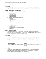
...numbering with SMBus support can access sensor data and other than SMBCLK (SMBus clock) and SMBDAT (SMBus data) should not be routed to the processor. On this output. 2.8.2 Internal I/O Connectors The internal I/O connectors are divided into the following functional groups: • Audio (see page 63...is designed to PCI bus connector 2 only (ATX expansion slot 6). Add-in cards with respect to PCI bus connector 2 only. Intel Desktop Board D865GVHZ Technical Product Specification ✏ NOTE The back panel audio line out connector is routed to power headphones or amplified ...
...numbering with SMBus support can access sensor data and other than SMBCLK (SMBus clock) and SMBDAT (SMBus data) should not be routed to the processor. On this output. 2.8.2 Internal I/O Connectors The internal I/O connectors are divided into the following functional groups: • Audio (see page 63...is designed to PCI bus connector 2 only (ATX expansion slot 6). Add-in cards with respect to PCI bus connector 2 only. Intel Desktop Board D865GVHZ Technical Product Specification ✏ NOTE The back panel audio line out connector is routed to power headphones or amplified ...

Product Specification
Page 65
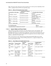
Power and Hardware Control Connectors Table 29. Technical Reference 2.8.2.3 Power and Hardware Control Connectors Figure 16 shows the location of the power and hardware control connectors. Rear Chassis Fan Connector Pin Signal Name 1 Control 2 +12 V 3 REAR_TACH_OUT 65 A B 13 12 34 31 1 3 20 11 1 F E Item A B C D E F Description Rear chassis fan +12 V power connector (ATX12V) Processor fan Main power Front chassis fan Chassis intrusion D C OM16409 For more information see: Table 29 Table 30 Table 31 Table 32 Table 33 Table 34 Figure 16.
Power and Hardware Control Connectors Table 29. Technical Reference 2.8.2.3 Power and Hardware Control Connectors Figure 16 shows the location of the power and hardware control connectors. Rear Chassis Fan Connector Pin Signal Name 1 Control 2 +12 V 3 REAR_TACH_OUT 65 A B 13 12 34 31 1 3 20 11 1 F E Item A B C D E F Description Rear chassis fan +12 V power connector (ATX12V) Processor fan Main power Front chassis fan Chassis intrusion D C OM16409 For more information see: Table 29 Table 30 Table 31 Table 32 Table 33 Table 34 Figure 16.
Product Specification
Page 66
... Ground 18 No connect 19 +5 V 20 +5 V 66 ATX12V, SFX12V, and TFX12V power supplies have an additional power lead that provides required supplemental power for the processor. Main Power Connector Pin Signal Name 1 +3.3 V 2 +3.3 V 3 Ground 4 +5 V 5 Ground 6 +5 V 7 Ground 8 PWRGD (Power Good) 9 +5 ...ON# (power supply remote on the desktop board, otherwise the board will not boot with the Desktop Board D865GVHZ. Intel Desktop Board D865GVHZ Technical Product Specification # INTEGRATOR'S NOTES • Use only ATX12V-, SFX12V-, or TFX12V-compliant power ...
... Ground 18 No connect 19 +5 V 20 +5 V 66 ATX12V, SFX12V, and TFX12V power supplies have an additional power lead that provides required supplemental power for the processor. Main Power Connector Pin Signal Name 1 +3.3 V 2 +3.3 V 3 Ground 4 +5 V 5 Ground 6 +5 V 7 Ground 8 PWRGD (Power Good) 9 +5 ...ON# (power supply remote on the desktop board, otherwise the board will not boot with the Desktop Board D865GVHZ. Intel Desktop Board D865GVHZ Technical Product Specification # INTEGRATOR'S NOTES • Use only ATX12V-, SFX12V-, or TFX12V-compliant power ...
Product Specification
Page 75
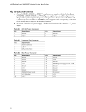
... Desktop Board. When the jumper is set to configure mode and the computer is displayed. The 3 maintenance menu is powered-up, the BIOS compares the processor version and the microcode version in connectors are removed and this connector is required. 75 BIOS Setup Configuration Jumper Settings Function/Mode Normal Jumper Setting...
... Desktop Board. When the jumper is set to configure mode and the computer is displayed. The 3 maintenance menu is powered-up, the BIOS compares the processor version and the microcode version in connectors are removed and this connector is required. 75 BIOS Setup Configuration Jumper Settings Function/Mode Normal Jumper Setting...
Product Specification
Page 78
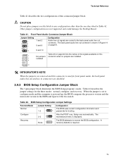
...system's usage model and not necessarily tied to a particular processor speed. Fan Connector Current Capability Fan Connector Processor fan Front chassis fan Rear chassis fan Maximum Available Current 1.0 A 0.6 A 0.6 A 78 Intel Desktop Board D865GVHZ Technical Product Specification 2.11 Electrical Considerations ...all three expansion slots filled) must not exceed 6 A. 2.11.3 Fan Connector Current Capability CAUTION The processor fan must be connected to the processor fan connector, not to determine the overall system power requirements. Maximum values assume a load placed on the...
...system's usage model and not necessarily tied to a particular processor speed. Fan Connector Current Capability Fan Connector Processor fan Front chassis fan Rear chassis fan Maximum Available Current 1.0 A 0.6 A 0.6 A 78 Intel Desktop Board D865GVHZ Technical Product Specification 2.11 Electrical Considerations ...all three expansion slots filled) must not exceed 6 A. 2.11.3 Fan Connector Current Capability CAUTION The processor fan must be connected to the processor fan connector, not to determine the overall system power requirements. Maximum values assume a load placed on the...

Product Specification
Page 79
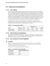
... listed in Table 43 when selecting a power supply for use of an Intel Pentium 4 processor operating above 2.80 GHz Failure to ensure appropriate airflow may result in reduced performance of both the processor and/or voltage regulator or, in some instances, damage to the desktop board... Failure to ensure proper cooling of the components on the board • A processor fan heatsink that have been tested with Intel desktop boards please refer to the following website: http://developer.intel.com/design/motherbd/cooling.htm All responsibility for determining the adequacy of any thermal ...
... listed in Table 43 when selecting a power supply for use of an Intel Pentium 4 processor operating above 2.80 GHz Failure to ensure appropriate airflow may result in reduced performance of both the processor and/or voltage regulator or, in some instances, damage to the desktop board... Failure to ensure proper cooling of the components on the board • A processor fan heatsink that have been tested with Intel desktop boards please refer to the following website: http://developer.intel.com/design/motherbd/cooling.htm All responsibility for determining the adequacy of any thermal ...
Product Specification
Page 80
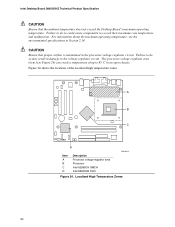
... of up to the voltage regulator circuit. Localized High Temperature Zones 80 Intel Desktop Board D865GVHZ Technical Product Specification CAUTION Ensure that proper airflow is maintained in the processor voltage regulator circuit. Failure to do so could cause components to exceed ...that the ambient temperature does not exceed the Desktop Board's maximum operating temperature. A B C D Item A B C D Description Processor voltage regulator area Processor Intel 82865GV GMCH Intel 82801EB ICH5 OM16414 Figure 24. Failure to do so may result in damage to 85 oC in Section 2.14.
... of up to the voltage regulator circuit. Localized High Temperature Zones 80 Intel Desktop Board D865GVHZ Technical Product Specification CAUTION Ensure that proper airflow is maintained in the processor voltage regulator circuit. Failure to do so could cause components to exceed ...that the ambient temperature does not exceed the Desktop Board's maximum operating temperature. A B C D Item A B C D Description Processor voltage regulator area Processor Intel 82865GV GMCH Intel 82801EB ICH5 OM16414 Figure 24. Failure to do so may result in damage to 85 oC in Section 2.14.


