
Product Specification
Page 5
...14 1.1.4 Block Diagram 15 1.2 Online Support ...16 1.3 Operating System Support 16 1.4 Design Specifications 17 1.5 Processor ...20 1.6 System Memory ...21 1.6.1 Memory Features 21 1.6.2 Memory Configurations 23 1.7 Intel® 865PE Chipset 28 1.7.1 AGP ...28 1.7.2 USB...29 1.7.3 IDE Support 30 1.7.4 Real-Time Clock, ... 33 1.9 IEEE 1394a-2000 Controller (Optional 33 1.10 Audio Subsystem...34 1.10.1 6-Channel Audio Subsystem (Optional 34 1.10.2 Intel® Flex 6 Audio Subsystem (Optional 36 1.10.3 Audio Connectors 37 1.10.4 Audio Subsystem Software 38 1.11 LAN Subsystem...39...
...14 1.1.4 Block Diagram 15 1.2 Online Support ...16 1.3 Operating System Support 16 1.4 Design Specifications 17 1.5 Processor ...20 1.6 System Memory ...21 1.6.1 Memory Features 21 1.6.2 Memory Configurations 23 1.7 Intel® 865PE Chipset 28 1.7.1 AGP ...28 1.7.2 USB...29 1.7.3 IDE Support 30 1.7.4 Real-Time Clock, ... 33 1.9 IEEE 1394a-2000 Controller (Optional 33 1.10 Audio Subsystem...34 1.10.1 6-Channel Audio Subsystem (Optional 34 1.10.2 Intel® Flex 6 Audio Subsystem (Optional 36 1.10.3 Audio Connectors 37 1.10.4 Audio Subsystem Software 38 1.11 LAN Subsystem...39...

Product Specification
Page 9
... 39. Boot Device Menu Options 92 51. Advanced Menu...98 57. Drive Configuration Submenu 103 61. DMA Channels ...53 15. Mic In Connector ...61 26. Processor Fan Connector 66 33. SATA/PATA Submenus 106 ix Audio Line Out Connector (Front Left and Right Out for Components 81 46. Voltage Regulator Fan...
... 39. Boot Device Menu Options 92 51. Advanced Menu...98 57. Drive Configuration Submenu 103 61. DMA Channels ...53 15. Mic In Connector ...61 26. Processor Fan Connector 66 33. SATA/PATA Submenus 106 ix Audio Line Out Connector (Front Left and Right Out for Components 81 46. Voltage Regulator Fan...
Product Specification
Page 11
1 Product Description What This Chapter Contains 1.1 Overview ...12 1.2 Online Support ...16 1.3 Operating System Support 16 1.4 Design Specifications 17 1.5 Processor ...20 1.6 System Memory ...21 1.7 Intel® 865PE Chipset 28 1.8 I/O Controller ...32 1.9 IEEE 1394a-2000 Controller (Optional 33 1.10 Audio Subsystem...34 1.11 LAN Subsystem...39 1.12 Hardware Management Subsystem 41 1.13 Power Management 43 11
1 Product Description What This Chapter Contains 1.1 Overview ...12 1.2 Online Support ...16 1.3 Operating System Support 16 1.4 Design Specifications 17 1.5 Processor ...20 1.6 System Memory ...21 1.7 Intel® 865PE Chipset 28 1.8 I/O Controller ...32 1.9 IEEE 1394a-2000 Controller (Optional 33 1.10 Audio Subsystem...34 1.11 LAN Subsystem...39 1.12 Hardware Management Subsystem 41 1.13 Power Management 43 11
Product Specification
Page 12
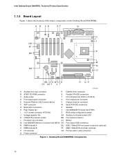
... Chipset Video USB Peripheral Interfaces Expansion Capabilities I/O Control Hardware Monitor Subsystem • Support for an Intel® Pentium® 4 processor in a mPGA478 socket with a 400/533/800 MHz system bus • Support for an Intel® Celeron® processor in a mPGA478 socket with a 400 MHz system bus • Four 184-pin DDR SDRAM Dual...
... Chipset Video USB Peripheral Interfaces Expansion Capabilities I/O Control Hardware Monitor Subsystem • Support for an Intel® Pentium® 4 processor in a mPGA478 socket with a 400/533/800 MHz system bus • Support for an Intel® Celeron® processor in a mPGA478 socket with a 400 MHz system bus • Four 184-pin DDR SDRAM Dual...
Product Specification
Page 14
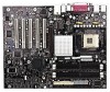
... Hub (FWH) I +12 V power connector (ATX12V) Z BIOS setup configuration jumper J Voltage regulator fan AA Auxiliary front panel power LED K mPGA478 processor socket BB Front panel connector L Processor fan connector CC Battery M Intel 82865PE Memory Controller Hub (MCH) DD Front panel USB connectors N DIMM channel A EE IEEE 1394a-2000 front panel connectors (optional) O DIMM...
... Hub (FWH) I +12 V power connector (ATX12V) Z BIOS setup configuration jumper J Voltage regulator fan AA Auxiliary front panel power LED K mPGA478 processor socket BB Front panel connector L Processor fan connector CC Battery M Intel 82865PE Memory Controller Hub (MCH) DD Front panel USB connectors N DIMM channel A EE IEEE 1394a-2000 front panel connectors (optional) O DIMM...
Product Specification
Page 15
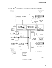
... functional areas of the Desktop Board D865PERL. = connector or socket Parallel ATA IDE Connectors (2) Parallel ATA IDE Interface mPGA478 System Bus Processor Socket (400/533/800 MHz) USB LPC Bus I/O Controller LPC Bus Back Panel/ Front Panel USB Ports Serial Port Parallel Port ...PS/2 Mouse PS/2 Keyboard Diskette Drive Connector AGP Interface Universal 0.8/1.5 V AGP 3.0 Connector Intel 82865PE Memory Controller Hub (MCH) AHA Bus LAN Connector Channel A DIMMs (2) Gigabit LAN PLC (Optional) CSA Interface Dual-Channel Memory Bus SMBus...
... functional areas of the Desktop Board D865PERL. = connector or socket Parallel ATA IDE Connectors (2) Parallel ATA IDE Interface mPGA478 System Bus Processor Socket (400/533/800 MHz) USB LPC Bus I/O Controller LPC Bus Back Panel/ Front Panel USB Ports Serial Port Parallel Port ...PS/2 Mouse PS/2 Keyboard Diskette Drive Connector AGP Interface Universal 0.8/1.5 V AGP 3.0 Connector Intel 82865PE Memory Controller Hub (MCH) AHA Bus LAN Connector Channel A DIMMs (2) Gigabit LAN PLC (Optional) CSA Interface Dual-Channel Memory Bus SMBus...

Product Specification
Page 16
...The Desktop Board D865PERL, look under "Desktop Board Products" or "Desktop Board Support" Available configurations for the Desktop Board D865PERL Processor data sheets ICH5 addressing Custom splash screens Audio software and utilities LAN software and drivers Visit this World Wide Web site: http://www... tested with drivers for other operating systems. • Third party vendors may offer other operating system in the list above. Intel Desktop Board D865PERL Technical Product Specification 1.2 Online Support To find information about Supported drivers Refer to Section 1.2, page 16 16
...The Desktop Board D865PERL, look under "Desktop Board Products" or "Desktop Board Support" Available configurations for the Desktop Board D865PERL Processor data sheets ICH5 addressing Custom splash screens Audio software and utilities LAN software and drivers Visit this World Wide Web site: http://www... tested with drivers for other operating systems. • Third party vendors may offer other operating system in the list above. Intel Desktop Board D865PERL Technical Product Specification 1.2 Online Support To find information about Supported drivers Refer to Section 1.2, page 16 16
Product Specification
Page 20
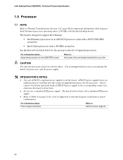
... below for the most up-to Thermal Considerations (Section 2.12, page 80) for the processor. Use of supported processors. Intel Desktop Board D865PERL Technical Product Specification 1.5 Processor ✏ NOTE Refer to -date list of unsupported processors can damage the board, the processor, and the power supply. # INTEGRATOR'S NOTES • Use only ATX12V-compliant power supplies with...
... below for the most up-to Thermal Considerations (Section 2.12, page 80) for the processor. Use of supported processors. Intel Desktop Board D865PERL Technical Product Specification 1.5 Processor ✏ NOTE Refer to -date list of unsupported processors can damage the board, the processor, and the power supply. # INTEGRATOR'S NOTES • Use only ATX12V-compliant power supplies with...
Product Specification
Page 21
... compliant with x16 organization are not supported. • 4 GB maximum total system memory. If non-SPD memory is clocked at 320 MHz. The processor's system bus frequency must be... DDR400 800 MHz DDR333 800 or 533 MHz (Note) DDR266 800, 533, or 400 MHz Note: When using ...an 800 MHz system bus frequency processor, DDR333 memory is installed, the BIOS will attempt to Section 2.2.1 on the total amount of DIMM... Product Description 1.6 System Memory 1.6.1 Memory Features The...
... compliant with x16 organization are not supported. • 4 GB maximum total system memory. If non-SPD memory is clocked at 320 MHz. The processor's system bus frequency must be... DDR400 800 MHz DDR333 800 or 533 MHz (Note) DDR266 800, 533, or 400 MHz Note: When using ...an 800 MHz system bus frequency processor, DDR333 memory is installed, the BIOS will attempt to Section 2.2.1 on the total amount of DIMM... Product Description 1.6 System Memory 1.6.1 Memory Features The...

Product Specification
Page 30
...ATAPI floppy drive. The Parallel ATA IDE interfaces support the following modes: • Programmed I/O (PIO): processor controls data transfer. • 8237-style DMA: DMA offloads the processor, supporting transfer rates of up to 16 MB/sec. • Ultra DMA: DMA protocol on IDE... The BIOS supports Logical Block Addressing (LBA) and Extended Cylinder Head Sector (ECHS) translation modes. A point-to 66 MB/sec. Intel Desktop Board D865PERL Technical Product Specification 1.7.3 IDE Support The board provides four IDE interface connectors: • Two Parallel ATA IDE connectors, which...
...ATAPI floppy drive. The Parallel ATA IDE interfaces support the following modes: • Programmed I/O (PIO): processor controls data transfer. • 8237-style DMA: DMA offloads the processor, supporting transfer rates of up to 16 MB/sec. • Ultra DMA: DMA protocol on IDE... The BIOS supports Logical Block Addressing (LBA) and Extended Cylinder Head Sector (ECHS) translation modes. A point-to 66 MB/sec. Intel Desktop Board D865PERL Technical Product Specification 1.7.3 IDE Support The board provides four IDE interface connectors: • Two Parallel ATA IDE connectors, which...

Product Specification
Page 41
...fan control ASIC (Standard Microsystems SMSC EMC6D101 or equivalent) include: • Internal ambient temperature sensor • Two remote thermal diode sensors for direct monitoring of processor temperature and ambient temperature sensing • Power supply monitoring of the fan connectors and sensors for thermal monitoring The Standard Microsystems SMSC EMC6D101 Refer to... Thermally monitored closed-loop fan control, for Management (WfM) specification. The computer is selected. 1.11.3 LAN Subsystem Software LAN software and drivers are available from Intel's World Wide Web site.
...fan control ASIC (Standard Microsystems SMSC EMC6D101 or equivalent) include: • Internal ambient temperature sensor • Two remote thermal diode sensors for direct monitoring of processor temperature and ambient temperature sensing • Power supply monitoring of the fan connectors and sensors for thermal monitoring The Standard Microsystems SMSC EMC6D101 Refer to... Thermally monitored closed-loop fan control, for Management (WfM) specification. The computer is selected. 1.11.3 LAN Subsystem Software LAN software and drivers are available from Intel's World Wide Web site.
Product Specification
Page 42
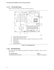
For information about The functions of the sensors and fan connectors. 3 1 1 3 A B 1 C 3 D 13 G FE OM15901 A Thermal diode, located on processor die B Remote ambient temperature sensor C Ambient temperature sensor (internal to Section 1.13.2.2, page 47 42 Intel Desktop Board D865PERL Technical Product Specification 1.12.1.2 Thermal Monitoring Figure 16 shows the location of the fan connectors...
For information about The functions of the sensors and fan connectors. 3 1 1 3 A B 1 C 3 D 13 G FE OM15901 A Thermal diode, located on processor die B Remote ambient temperature sensor C Ambient temperature sensor (internal to Section 1.13.2.2, page 47 42 Intel Desktop Board D865PERL Technical Product Specification 1.12.1.2 Thermal Monitoring Figure 16 shows the location of the fan connectors...

Product Specification
Page 45
...ACPI, the operating system directs all system and device power state transitions. Power States and Targeted System Power Global States Sleeping States Processor States Device States Targeted System Power (Note 1) G0 - S0 - working C1 - Notes: 1. The operating system uses information ...from the computer. Table 10. mechanical off . Processor stopped S3 - S5 - working state. D3 - no power except for wake-up logic. Dependent on the system configuration, including add-...
...ACPI, the operating system directs all system and device power state transitions. Power States and Targeted System Power Global States Sleeping States Processor States Device States Targeted System Power (Note 1) G0 - S0 - working C1 - Notes: 1. The operating system uses information ...from the computer. Table 10. mechanical off . Processor stopped S3 - S5 - working state. D3 - no power except for wake-up logic. Dependent on the system configuration, including add-...

Product Specification
Page 47
...Wired to a fan tachometer input of the hardware monitoring and fan control ASIC. • Closed-loop fan control that can be connected to the processor fan connector, not to a fan tachometer input of the hardware monitoring and fan control ASIC. 47 Fan is off when the system is off ...control that can turn off or in the S3, S4, or S5 state. • Wired to a chassis fan connector. Fan Connector Function/Operation Connector Description Processor fan Front and rear chassis fans Voltage regulator fan • +12 V DC connection for a system or chassis fan. • Fan is on or ...
...Wired to a fan tachometer input of the hardware monitoring and fan control ASIC. • Closed-loop fan control that can be connected to the processor fan connector, not to a fan tachometer input of the hardware monitoring and fan control ASIC. 47 Fan is off when the system is off ...control that can turn off or in the S3, S4, or S5 state. • Wired to a chassis fan connector. Fan Connector Function/Operation Connector Description Processor fan Front and rear chassis fans Voltage regulator fan • +12 V DC connection for a system or chassis fan. • Fan is on or ...
Product Specification
Page 62
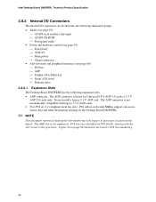
... 1.5 V AGP 2.0 cards only. Do not install a legacy 3.3 V AGP card. Intel Desktop Board D865PERL Technical Product Specification 2.8.2 Internal I/O Connectors The internal I/O connectors are identified as PCI slot #x, starting with respect to the processor. The AGP connector is not mechanically compatible with legacy 3.3 V AGP cards. •... on the Desktop Board D865PERL. ✏ NOTE This document references back-panel slot numbering with the slot closest to processor location on page 68 illustrates the board's PCI slot numbering. 62 Figure 22 on the board. PCI slots are ...
... 1.5 V AGP 2.0 cards only. Do not install a legacy 3.3 V AGP card. Intel Desktop Board D865PERL Technical Product Specification 2.8.2 Internal I/O Connectors The internal I/O connectors are identified as PCI slot #x, starting with respect to the processor. The AGP connector is not mechanically compatible with legacy 3.3 V AGP cards. •... on the Desktop Board D865PERL. ✏ NOTE This document references back-panel slot numbering with the slot closest to processor location on page 68 illustrates the board's PCI slot numbering. 62 Figure 22 on the board. PCI slots are ...
Product Specification
Page 65
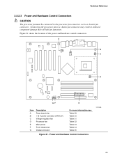
...A 1 3 12 34 B 1 C 3 1 3 D 1 13 20 11 1 GF E Item A B C D E F G Description Rear chassis fan +12 V power connector (ATX12V) Voltage regulator fan Processor fan Main power Front chassis fan Chassis intrusion For more information see: Table 29 Table 30 Table 31 Table 32 Table 33 Table 34 Table... 35 Figure 21. Connecting the processor fan to a chassis fan connector. Technical Reference 2.8.2.3 Power and Hardware Control Connectors CAUTION The processor fan must be connected to the processor fan connector, not to a chassis fan connector may result in ...
...A 1 3 12 34 B 1 C 3 1 3 D 1 13 20 11 1 GF E Item A B C D E F G Description Rear chassis fan +12 V power connector (ATX12V) Voltage regulator fan Processor fan Main power Front chassis fan Chassis intrusion For more information see: Table 29 Table 30 Table 31 Table 32 Table 33 Table 34 Table... 35 Figure 21. Connecting the processor fan to a chassis fan connector. Technical Reference 2.8.2.3 Power and Hardware Control Connectors CAUTION The processor fan must be connected to the processor fan connector, not to a chassis fan connector may result in ...

Product Specification
Page 66
...D865PERL will not boot with the Desktop Board D865PERL. ATX12V power supplies have an additional power lead that provides required supplemental power for the Intel Pentium 4 processor. Rear Chassis Fan Connector Pin Signal Name 1 Control 2 +12 V 3 TACH Table 30. ATX12V Power Connector Pin Signal Name 1 ... not boot if the ATX12V power supply is not connected to Section 1.13.2.1, page 47 Section 1.13.2.2, page 47 Table 29. Processor Fan Connector Pin Signal Name 1 Ground / Control 2 +12 V 3 TACH 66 For information about The power connector The functions ...
...D865PERL will not boot with the Desktop Board D865PERL. ATX12V power supplies have an additional power lead that provides required supplemental power for the Intel Pentium 4 processor. Rear Chassis Fan Connector Pin Signal Name 1 Control 2 +12 V 3 TACH Table 30. ATX12V Power Connector Pin Signal Name 1 ... not boot if the ATX12V power supply is not connected to Section 1.13.2.1, page 47 Section 1.13.2.2, page 47 Table 29. Processor Fan Connector Pin Signal Name 1 Ground / Control 2 +12 V 3 TACH 66 For information about The power connector The functions ...
Product Specification
Page 75
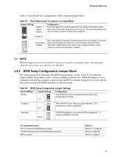
... are removed and this connector/jumper block. When the jumper is set to configure mode and the computer is powered-up, the BIOS compares the processor version and the microcode version in and front out signals if 6-channel audio (line out signals if 2-channel audio) are available for connection to front...
... are removed and this connector/jumper block. When the jumper is set to configure mode and the computer is powered-up, the BIOS compares the processor version and the microcode version in and front out signals if 6-channel audio (line out signals if 2-channel audio) are available for connection to front...
Product Specification
Page 78
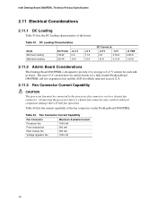
...all five expansion slots and the AGP slot filled) must not exceed 12 A. 2.11.3 Fan Connector Current Capability CAUTION The processor fan must be connected to the processor fan connector, not to a chassis fan connector may result in boards for each addin board. The total +5 V current ...draw for add-in onboard component damage that will halt fan operation. Table 44. Intel Desktop Board D865PERL Technical Product Specification 2.11 ...
...all five expansion slots and the AGP slot filled) must not exceed 12 A. 2.11.3 Fan Connector Current Capability CAUTION The processor fan must be connected to the processor fan connector, not to a chassis fan connector may result in boards for each addin board. The total +5 V current ...draw for add-in onboard component damage that will halt fan operation. Table 44. Intel Desktop Board D865PERL Technical Product Specification 2.11 ...
Product Specification
Page 80
...30) can reach a temperature of up to 85 °C in Section 2.14. Intel Desktop Board D865PERL Technical Product Specification 2.12 Thermal Considerations CAUTION The use of an Intel Pentium 4 processor operating above 2.80 GHz Failure to ensure appropriate airflow may result in damage to the ... to ensure proper cooling of the components on the board • A processor fan heatsink that the ambient temperature does not exceed the Desktop Board D865PERL's maximum operating temperature. Intel makes no warranties or representations that have been tested with adequate thermal performance....
...30) can reach a temperature of up to 85 °C in Section 2.14. Intel Desktop Board D865PERL Technical Product Specification 2.12 Thermal Considerations CAUTION The use of an Intel Pentium 4 processor operating above 2.80 GHz Failure to ensure appropriate airflow may result in damage to the ... to ensure proper cooling of the components on the board • A processor fan heatsink that the ambient temperature does not exceed the Desktop Board D865PERL's maximum operating temperature. Intel makes no warranties or representations that have been tested with adequate thermal performance....


