

Product Specification
Page 12
... Chipset Video Audio I/O Control USB Peripheral Interfaces LAN Support BIOS Instantly Available PC Technology ATX (12.00 inches by 9.60 inches [304.80 millimeters by 243.84 millimeters]) Support for an Intel® Pentium® 4 processor in the 4 Mbit FWH) • Support for...8226; One diskette drive interface • PS/2* keyboard and mouse ports The board provides one of the Desktop Boards D915GEV and D915GRF. Intel Desktop Board D915GEV/D915GRF Technical Product Specification 1.2 Overview 1.2.1 Feature Summary Table 1 summarizes the major features of the following: • Gigabit...
... Chipset Video Audio I/O Control USB Peripheral Interfaces LAN Support BIOS Instantly Available PC Technology ATX (12.00 inches by 9.60 inches [304.80 millimeters by 243.84 millimeters]) Support for an Intel® Pentium® 4 processor in the 4 Mbit FWH) • Support for...8226; One diskette drive interface • PS/2* keyboard and mouse ports The board provides one of the Desktop Boards D915GEV and D915GRF. Intel Desktop Board D915GEV/D915GRF Technical Product Specification 1.2 Overview 1.2.1 Feature Summary Table 1 summarizes the major features of the following: • Gigabit...
Product Specification
Page 13
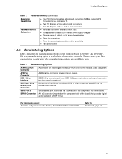
Manufacturing Options ATAPI CD-ROM Connector A connector for attaching an internal CD-ROM drive to the onboard audio subsystem ATX Fan Connector Additional fan connector for the Desktop Boards D915GEV and D915GRF Refer to monitor fan activity • Fan speed control 1.2.2...fan control ASIC • Voltage sense to detect out of range power supply voltages • Thermal sense to you. Please contact your Intel representative to determine which manufacturing options are available to detect out of the board) that provides digital audio signals in all marketing channels. ...
Manufacturing Options ATAPI CD-ROM Connector A connector for attaching an internal CD-ROM drive to the onboard audio subsystem ATX Fan Connector Additional fan connector for the Desktop Boards D915GEV and D915GRF Refer to monitor fan activity • Fan speed control 1.2.2...fan control ASIC • Voltage sense to detect out of range power supply voltages • Thermal sense to you. Please contact your Intel representative to determine which manufacturing options are available to detect out of the board) that provides digital audio signals in all marketing channels. ...

Product Specification
Page 35
1.11.2 Thermal Monitoring Figure 13 shows the location of the sensors and fan connectors. 13 3 1 Product Description A CB 4 1 D 13 1 3 Item A B C D E F G H HG F E OM16669 Description Thermal diode, located on processor die Remote ambient temperature sensor Ambient temperature sensor, internal to hardware monitoring and fan control ASIC Processor fan Rear chassis fan 1 Front chassis fan ATX fan (optional) Rear chassis fan 2 Figure 13. Thermal Monitoring 35
1.11.2 Thermal Monitoring Figure 13 shows the location of the sensors and fan connectors. 13 3 1 Product Description A CB 4 1 D 13 1 3 Item A B C D E F G H HG F E OM16669 Description Thermal diode, located on processor die Remote ambient temperature sensor Ambient temperature sensor, internal to hardware monitoring and fan control ASIC Processor fan Rear chassis fan 1 Front chassis fan ATX fan (optional) Rear chassis fan 2 Figure 13. Thermal Monitoring 35
Product Specification
Page 65
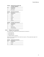
... Connectors The board has three standard and one optional chassis fan connectors: • Front chassis fan • Rear chassis fan 1 • Rear chassis fan 2 • ATX fan connector (optional) Table 26 lists the signal names for the chassis fan connectors. These signal names apply to all chassis fan connectors. Table 26...
... Connectors The board has three standard and one optional chassis fan connectors: • Front chassis fan • Rear chassis fan 1 • Rear chassis fan 2 • ATX fan connector (optional) Table 26 lists the signal names for the chassis fan connectors. These signal names apply to all chassis fan connectors. Table 26...

Product Specification
Page 67
...Name 1 Ground 3 +12 V Pin Signal Name 2 Ground 4 +12 V Table 29. The SMBus is connected to PCI Conventional bus connector 2 only (ATX expansion slot 6). This enables PCI Conventional bus add-in cards with SMBus support to 8 GBytes/sec. • Two PCI Express x1 connectors. The SMBus ...capable. • SMBus signals are as follows: The SMBus clock line is connected to support only a PCI Express x1 link when the Intel GMA900 graphics controller is configured to pin A40. Note the following add-in card connectors: • One PCI Express x16 connector supporting ...
...Name 1 Ground 3 +12 V Pin Signal Name 2 Ground 4 +12 V Table 29. The SMBus is connected to PCI Conventional bus connector 2 only (ATX expansion slot 6). This enables PCI Conventional bus add-in cards with SMBus support to 8 GBytes/sec. • Two PCI Express x1 connectors. The SMBus ...capable. • SMBus signals are as follows: The SMBus clock line is connected to support only a PCI Express x1 link when the Intel GMA900 graphics controller is configured to pin A40. Note the following add-in card connectors: • One PCI Express x16 connector supporting ...
Product Specification
Page 72
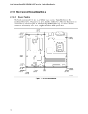
... form factor. Board Dimensions 6.450 6.200 [163.83] [157.48] OM16674 72 Location of the I/O connectors and mounting holes are given in compliance with the ATX specification. 6.500 [165.10] 6.100 [154.94] 1.800 [45.72] 5.200 [132.08] 0.00 2.850 [72.39] 3.100 [78.74]...] 2.600 0.00 [66.04] Figure 22. Dimensions are in inches [millimeters]. The outer dimensions are designed to fit into an ATX-form-factor chassis. Intel Desktop Board D915GEV/D915GRF Technical Product Specification 2.10 Mechanical Considerations 2.10.1 Form Factor The boards are 12.00 inches by 9.60 inches...
... form factor. Board Dimensions 6.450 6.200 [163.83] [157.48] OM16674 72 Location of the I/O connectors and mounting holes are given in compliance with the ATX specification. 6.500 [165.10] 6.100 [154.94] 1.800 [45.72] 5.200 [132.08] 0.00 2.850 [72.39] 3.100 [78.74]...] 2.600 0.00 [66.04] Figure 22. Dimensions are in inches [millimeters]. The outer dimensions are designed to fit into an ATX-form-factor chassis. Intel Desktop Board D915GEV/D915GRF Technical Product Specification 2.10 Mechanical Considerations 2.10.1 Form Factor The boards are 12.00 inches by 9.60 inches...

Product Specification
Page 73
... for I/O shields relative to chassis requirements are given in inches to pass certification testing. NOTE The I/O shield drawing in the ATX specification. Systems based on these boards need the back panel I /O Shield Dimensions OM17166 73 The figure also indicates the position of... ±0.02 inches. Dimensions are described in this document is available from Intel. 1.55 REF [0.061] 162.3 REF [6.390] 20. ± 0.254 TYP [0.787 ± 0.10] 159.2 ± 0.12 [6.268 ± 0.005] 1.6 ±...
... for I/O shields relative to chassis requirements are given in inches to pass certification testing. NOTE The I/O shield drawing in the ATX specification. Systems based on these boards need the back panel I /O Shield Dimensions OM17166 73 The figure also indicates the position of... ±0.02 inches. Dimensions are described in this document is available from Intel. 1.55 REF [0.061] 162.3 REF [6.390] 20. ± 0.254 TYP [0.787 ± 0.10] 159.2 ± 0.12 [6.268 ± 0.005] 1.6 ±...

Product Specification
Page 74
...fan connector. Table 36. Fan Connector Current Capability Fan Connector Processor fan Front chassis fan Rear chassis fan Rear chassis fan 2 ATX fan (optional) Maximum Available Current 1000 mA 600 mA 600 mA 600 mA 600 mA 74 Minimum values assume a light ... Connector Current Capability CAUTION The processor fan must be connected to the processor fan connector, not to a particular processor speed. Intel Desktop Board D915GEV/D915GRF Technical Product Specification 2.11 Electrical Considerations 2.11.1 DC Loading Table 35 lists the DC loading characteristics of the ...
...fan connector. Table 36. Fan Connector Current Capability Fan Connector Processor fan Front chassis fan Rear chassis fan Rear chassis fan 2 ATX fan (optional) Maximum Available Current 1000 mA 600 mA 600 mA 600 mA 600 mA 74 Minimum values assume a light ... Connector Current Capability CAUTION The processor fan must be connected to the processor fan connector, not to a particular processor speed. Intel Desktop Board D915GEV/D915GRF Technical Product Specification 2.11 Electrical Considerations 2.11.1 DC Loading Table 35 lists the DC loading characteristics of the ...

Product Specification
Page 75
... (Section 4.2.1.2) • All timing parameters (Section 4.2.1.3) • All voltage tolerances (Section 4.2.2) 75 Failure to the power usage values listed in the indicated sections of the ATX form factor specification. • The potential relation between 3.3 VDC and +5 VDC power rails (Section 4.2) • The current capability of standby current required depends on configurations...
... (Section 4.2.1.2) • All timing parameters (Section 4.2.1.3) • All voltage tolerances (Section 4.2.2) 75 Failure to the power usage values listed in the indicated sections of the ATX form factor specification. • The potential relation between 3.3 VDC and +5 VDC power rails (Section 4.2) • The current capability of standby current required depends on configurations...

