Product Specification
Page 5
...12 1.3.1 Feature Summary 12 1.3.2 Manufacturing Options 13 1.3.3 Board Layouts 14 1.3.4 Block Diagram 18 1.4 Online Support ...19 1.5 Processor ...19 1.6 System Memory ...20 1.6.1 Memory Configurations 21 1.7 Intel® 915P Chipset ...25 1.7.1 USB ...25 1.7.2 IDE Support 25 1.7.3 Real-Time Clock, CMOS SRAM, and Battery 27... Subsystem ...29 1.10.1 Audio Subsystem Software 29 1.10.2 Audio Connectors 29 1.10.3 Intel® High Definition Audio Subsystem 30 1.11 LAN Subsystem...31 1.11.1 Intel® 82562EZ Physical Layer Interface Device 31 1.11.2 Alert Standard Format (ASF) Support ...
...12 1.3.1 Feature Summary 12 1.3.2 Manufacturing Options 13 1.3.3 Board Layouts 14 1.3.4 Block Diagram 18 1.4 Online Support ...19 1.5 Processor ...19 1.6 System Memory ...20 1.6.1 Memory Configurations 21 1.7 Intel® 915P Chipset ...25 1.7.1 USB ...25 1.7.2 IDE Support 25 1.7.3 Real-Time Clock, CMOS SRAM, and Battery 27... Subsystem ...29 1.10.1 Audio Subsystem Software 29 1.10.2 Audio Connectors 29 1.10.3 Intel® High Definition Audio Subsystem 30 1.11 LAN Subsystem...31 1.11.1 Intel® 82562EZ Physical Layer Interface Device 31 1.11.2 Alert Standard Format (ASF) Support ...

Product Specification
Page 8
... Connector 68 33. Fan Connector Current Capability 76 39. Thermal Considerations for Omni-directional Airflow 77 28. Intel Desktop Board D915PCY/D915PCM Technical Product Specification 26. Processor Heatsink for Components 79 40. DMA Channels ...53 13. Interrupts ...56 16. PCI Interrupt Routing Map ...Summary of Pressing the Power Switch 37 9. D915PCY Board Components Shown in Figure 18 61 19. Chassis Intrusion Connector 64 25. Processor Fan Connector 65 28. States for a One-Color Power LED 69 35. Front Panel Connector 68 34. Component-side Connectors Shown...
... Connector 68 33. Fan Connector Current Capability 76 39. Thermal Considerations for Omni-directional Airflow 77 28. Intel Desktop Board D915PCY/D915PCM Technical Product Specification 26. Processor Heatsink for Components 79 40. DMA Channels ...53 13. Interrupts ...56 16. PCI Interrupt Routing Map ...Summary of Pressing the Power Switch 37 9. D915PCY Board Components Shown in Figure 18 61 19. Chassis Intrusion Connector 64 25. Processor Fan Connector 65 28. States for a One-Color Power LED 69 35. Front Panel Connector 68 34. Component-side Connectors Shown...
Product Specification
Page 11
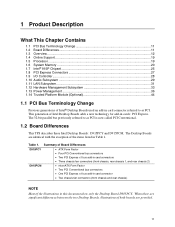
... What This Chapter Contains 1.1 PCI Bus Terminology Change 11 1.2 Board Differences...11 1.3 Overview ...12 1.4 Online Support ...19 1.5 Processor ...19 1.6 System Memory ...20 1.7 Intel® 915P Chipset ...25 1.8 PCI Express Connectors 27 1.9 I/O Controller...28 1.10 Audio Subsystem ...29 1.11 LAN Subsystem...31...Subsystem 33 1.13 Power Management 36 1.14 Trusted Platform Module (Optional 44 1.1 PCI Bus Terminology Change Previous generations of Intel® Desktop Boards used an add-in card connector referred to as PCI. Summary of Board Differences D915PCY • ATX...
... What This Chapter Contains 1.1 PCI Bus Terminology Change 11 1.2 Board Differences...11 1.3 Overview ...12 1.4 Online Support ...19 1.5 Processor ...19 1.6 System Memory ...20 1.7 Intel® 915P Chipset ...25 1.8 PCI Express Connectors 27 1.9 I/O Controller...28 1.10 Audio Subsystem ...29 1.11 LAN Subsystem...31...Subsystem 33 1.13 Power Management 36 1.14 Trusted Platform Module (Optional 44 1.1 PCI Bus Terminology Change Previous generations of Intel® Desktop Boards used an add-in card connector referred to as PCI. Summary of Board Differences D915PCY • ATX...

Product Specification
Page 12
....84 millimeters]) • D915PCM: microATX Form Factor (9.60 inches by 9.60 inches [243.84 millimeters by 243.84 millimeters]) Support for an Intel® Pentium® 4 processor in an LGA775 socket with an 800 or 533 MHz system bus • Four 240-pin DDR2 SDRAM Dual Inline Memory Module (DIMM) sockets... • Support for DDR2 533 MHz or DDR2 400 MHz DIMMs • Support for PCI Express Revision 1.0a • Suspend to 4 GB of system memory Intel®...
....84 millimeters]) • D915PCM: microATX Form Factor (9.60 inches by 9.60 inches [243.84 millimeters by 243.84 millimeters]) Support for an Intel® Pentium® 4 processor in an LGA775 socket with an 800 or 533 MHz system bus • Four 240-pin DDR2 SDRAM Dual Inline Memory Module (DIMM) sockets... • Support for DDR2 533 MHz or DDR2 400 MHz DIMMs • Support for PCI Express Revision 1.0a • Suspend to 4 GB of system memory Intel®...
Product Specification
Page 18
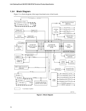
... 1 PCI Express x1 Slot 2 D915PCY only Parallel ATA IDE Connector Parallel ATA IDE Interface LGA775 Processor Socket System Bus (800/533 MHz) PCI Express x16 Interface PCI Express x16 Connector Intel 82915P Memory Controller Hub (MCH) Channel A DIMMs (2) Channel B DIMMs (2) Dual-Channel Memory...Ports LPC Bus I/O Controller LPC Bus Serial Ports Parallel Port PS/2 Mouse PS/2 Keyboard Diskette Drive Connector Intel 82801FB I/O Controller Hub (ICH6) 4 Mbit Firmware Hub (FWH) Intel 915P Chipset TPM Component (Optional) 10/100 LAN PLC LAN Connector IEEE-1394a Connectors (Optional) PCI ...
... 1 PCI Express x1 Slot 2 D915PCY only Parallel ATA IDE Connector Parallel ATA IDE Interface LGA775 Processor Socket System Bus (800/533 MHz) PCI Express x16 Interface PCI Express x16 Connector Intel 82915P Memory Controller Hub (MCH) Channel A DIMMs (2) Channel B DIMMs (2) Dual-Channel Memory...Ports LPC Bus I/O Controller LPC Bus Serial Ports Parallel Port PS/2 Mouse PS/2 Keyboard Diskette Drive Connector Intel 82801FB I/O Controller Hub (ICH6) 4 Mbit Firmware Hub (FWH) Intel 915P Chipset TPM Component (Optional) 10/100 LAN PLC LAN Connector IEEE-1394a Connectors (Optional) PCI ...

Product Specification
Page 19
... Refer to Section 2.8.2.2, page 66 19 Supported processors for the D915PCY board Supported processors for the most up-to support Intel Pentium 4 processors in an LGA775 processor socket with an 800 or 533 MHz system bus. INTEGRATOR'S NOTE Use only ATX12V-compliant power supplies. Use of supported processors. Intel Desktop Boards D915PCY and D915PCM under "Desktop Board...
... Refer to Section 2.8.2.2, page 66 19 Supported processors for the D915PCY board Supported processors for the most up-to support Intel Pentium 4 processors in an LGA775 processor socket with an 800 or 533 MHz system bus. INTEGRATOR'S NOTE Use only ATX12V-compliant power supplies. Use of supported processors. Intel Desktop Boards D915PCY and D915PCM under "Desktop Board...
Product Specification
Page 25
...controller for full-speed devices. The Parallel ATA IDE interface supports the following devices: • Intel 82915P Memory Controller Hub (MCH) with Direct Media Interface (DMI) interconnect • Intel 82801FB I/O Controller Hub (ICH6) with dual stacked back panel connectors adjacent to the audio ...interconnect • Firmware Hub (FWH) The MCH is a centralized controller for the board's I /O (PIO): processor controls data transfer. • 8237-style DMA: DMA offloads the processor, supporting transfer rates of up to Figure 17, page 58 Figure 18, page 60 Figure 19, page 62 ...
...controller for full-speed devices. The Parallel ATA IDE interface supports the following devices: • Intel 82915P Memory Controller Hub (MCH) with Direct Media Interface (DMI) interconnect • Intel 82801FB I/O Controller Hub (ICH6) with dual stacked back panel connectors adjacent to the audio ...interconnect • Firmware Hub (FWH) The MCH is a centralized controller for the board's I /O (PIO): processor controls data transfer. • 8237-style DMA: DMA offloads the processor, supporting transfer rates of up to Figure 17, page 58 Figure 18, page 60 Figure 19, page 62 ...
Product Specification
Page 32
... installed in Figure 12 below). LAN link is not established. Yellow Off 10 Mbits/sec data rate is occurring. Intel Desktop Board D915PCY/D915PCM Technical Product Specification 1.11.1.1 RJ-45 LAN Connector with Integrated LEDs Two LEDs are built into...LAN connector (shown in PCI Conventional bus slot 2: • Monitoring of system firmware progress events, including: BIOS present Primary processor initialization Memory initialization Video initialization PCI resource configuration Hard-disk initialization User authentication Starting operating system boot process • Monitoring of...
... installed in Figure 12 below). LAN link is not established. Yellow Off 10 Mbits/sec data rate is occurring. Intel Desktop Board D915PCY/D915PCM Technical Product Specification 1.11.1.1 RJ-45 LAN Connector with Integrated LEDs Two LEDs are built into...LAN connector (shown in PCI Conventional bus slot 2: • Monitoring of system firmware progress events, including: BIOS present Primary processor initialization Memory initialization Video initialization PCI resource configuration Hard-disk initialization User authentication Starting operating system boot process • Monitoring of...

Product Specification
Page 33
...hardware monitoring and fan control ASIC include: • Internal ambient temperature sensor • Two remote thermal diode sensors for direct monitoring of processor temperature and ambient temperature sensing • Power supply monitoring of the fan connectors and sensors for thermal monitoring on or off as needed ... • Wireless LAN protocols 802.11 b, g • 11 Mbps performance with 802.11b • 54 Mbps performance with the Wired for Intel 82801FBW (ICH6W) based SKUs that can adjust the fan speed or switch the fans on the D916PCM board Refer to a home or small office ...
...hardware monitoring and fan control ASIC include: • Internal ambient temperature sensor • Two remote thermal diode sensors for direct monitoring of processor temperature and ambient temperature sensing • Power supply monitoring of the fan connectors and sensors for thermal monitoring on or off as needed ... • Wireless LAN protocols 802.11 b, g • 11 Mbps performance with 802.11b • 54 Mbps performance with the Wired for Intel 82801FBW (ICH6W) based SKUs that can adjust the fan speed or switch the fans on the D916PCM board Refer to a home or small office ...
Product Specification
Page 34
Intel Desktop Board D915PCY/D915PCM Technical Product Specification 1.12.2 Thermal Monitoring Figure 13 shows the location of the sensors and fan connectors for D915PCY Board 34 Thermal Monitoring for the D915PCY board. 13 3 1 A CB 4 1 D 13 1 3 Item A B C D E F G H HG F E OM17055 Description Thermal diode, located on processor die Remote ambient temperature sensor Ambient temperature sensor, internal to hardware monitoring and fan control ASIC Processor fan Rear chassis fan 1 Front chassis fan ATX fan (optional) Rear chassis fan 2 Figure 13.
Intel Desktop Board D915PCY/D915PCM Technical Product Specification 1.12.2 Thermal Monitoring Figure 13 shows the location of the sensors and fan connectors for D915PCY Board 34 Thermal Monitoring for the D915PCY board. 13 3 1 A CB 4 1 D 13 1 3 Item A B C D E F G H HG F E OM17055 Description Thermal diode, located on processor die Remote ambient temperature sensor Ambient temperature sensor, internal to hardware monitoring and fan control ASIC Processor fan Rear chassis fan 1 Front chassis fan ATX fan (optional) Rear chassis fan 2 Figure 13.
Product Specification
Page 35
Product Description Figure 14 shows the location of the sensors and fan connectors for D915PCM Board 1.12.3 Fan Monitoring Fan monitoring can be implemented using Intel® Desktop Utilities, LANDesk* software, or thirdparty software. Thermal Monitoring for the D915PCM board. 3 1 A CB 4 1 D 1 3 Item A B C D E F F E OM17057 ...with the Desktop Board. The level of the fan connectors Refer to hardware monitoring and fan control ASIC Processor fan Rear chassis fan Front chassis fan Figure 14. For information about The functions of monitoring and control is dependent on...
Product Description Figure 14 shows the location of the sensors and fan connectors for D915PCM Board 1.12.3 Fan Monitoring Fan monitoring can be implemented using Intel® Desktop Utilities, LANDesk* software, or thirdparty software. Thermal Monitoring for the D915PCM board. 3 1 A CB 4 1 D 1 3 Item A B C D E F F E OM17057 ...with the Desktop Board. The level of the fan connectors Refer to hardware monitoring and fan control ASIC Processor fan Rear chassis fan Front chassis fan Figure 14. For information about The functions of monitoring and control is dependent on...

Product Specification
Page 38
...power to RAM. working state. sleeping state S1 - D3 - Power States and Targeted System Power Global States Sleeping States Processor States Device States Targeted System Power (Note 1) G0 - sleeping state G2/S5 S3 - device specification specific. Total system ...power is dependent on the standby power consumption of the various system and power states. Intel Desktop Board D915PCY/D915PCM Technical Product Specification Table 9 lists the power states supported by battery or external source. working D0 -...
...power to RAM. working state. sleeping state S1 - D3 - Power States and Targeted System Power Global States Sleeping States Processor States Device States Targeted System Power (Note 1) G0 - sleeping state G2/S5 S3 - device specification specific. Total system ...power is dependent on the standby power consumption of the various system and power states. Intel Desktop Board D915PCY/D915PCM Technical Product Specification Table 9 lists the power states supported by battery or external source. working D0 -...

Product Specification
Page 40
... monitoring for the D915PCY board The location of the fan connectors and sensors for thermal monitoring for the D915PCM board The signal names of the processor fan connector The signal names of the fan connectors is as follows: • The fans are off when the board is wired to the ...power state it is in the S3, S4, or S5 state. • Each fan connector is off the system power through system control. Intel Desktop Board D915PCY/D915PCM Technical Product Specification Resume on Ring enables telephony devices to access the computer when it was in before power was interrupted...
... monitoring for the D915PCY board The location of the fan connectors and sensors for thermal monitoring for the D915PCM board The signal names of the processor fan connector The signal names of the fan connectors is as follows: • The fans are off when the board is wired to the ...power state it is in the S3, S4, or S5 state. • Each fan connector is off the system power through system control. Intel Desktop Board D915PCY/D915PCM Technical Product Specification Resume on Ring enables telephony devices to access the computer when it was in before power was interrupted...
Product Specification
Page 65
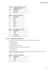
... connectors for the chassis fan connectors. Serial ATA Connectors Pin Signal Name 1 Ground 2 TXP 3 TXN 4 Ground 5 RXN 6 RXP 7 Ground Table 27. Technical Reference Table 25. Processor Fan Connector Pin Signal Name 1 Ground 2 +12 V 3 FAN_TACH 4 FAN_CONTROL 2.8.2.1 Chassis Fan Connectors The D915PCY board has three standard and one optional chassis fan connectors: •...
... connectors for the chassis fan connectors. Serial ATA Connectors Pin Signal Name 1 Ground 2 TXP 3 TXN 4 Ground 5 RXN 6 RXP 7 Ground Table 27. Technical Reference Table 25. Processor Fan Connector Pin Signal Name 1 Ground 2 +12 V 3 FAN_TACH 4 FAN_CONTROL 2.8.2.1 Chassis Fan Connectors The D915PCY board has three standard and one optional chassis fan connectors: •...
Product Specification
Page 66
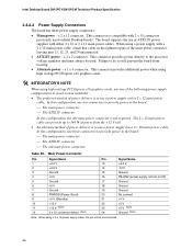
... from the +12 V rail. • An alternate method of power delivery is to use two connectors to provide power to the processor voltage regulator and must always be unconnected. 66 When using a 2 x 10 power supply cable, this configuration, use of power from...No connect 21 +5 V 22 +5 V 23 +5 V (Note) 24 Ground (Note) Note: When using a power supply with a 2 x 12 main power cable. Intel Desktop Board D915PCY/D915PCM Technical Product Specification 2.8.2.2 Power Supply Connectors The board has three power supply connectors: • Main power - a 2 x 2 connector. a 2 x...
... from the +12 V rail. • An alternate method of power delivery is to use two connectors to provide power to the processor voltage regulator and must always be unconnected. 66 When using a 2 x 10 power supply cable, this configuration, use of power from...No connect 21 +5 V 22 +5 V 23 +5 V (Note) 24 Ground (Note) Note: When using a power supply with a 2 x 12 main power cable. Intel Desktop Board D915PCY/D915PCM Technical Product Specification 2.8.2.2 Power Supply Connectors The board has three power supply connectors: • Main power - a 2 x 2 connector. a 2 x...

Product Specification
Page 71
... is displayed. Recovery None 1 The BIOS attempts to configure mode and the computer is required. 71 A 3 recovery diskette is powered-up, the BIOS compares the processor version and the microcode version in the same location on . Figure 23 shows the location of the Jumper Block OM17061 Table 36. The 3 maintenance menu...
... is displayed. Recovery None 1 The BIOS attempts to configure mode and the computer is required. 71 A 3 recovery diskette is powered-up, the BIOS compares the processor version and the microcode version in the same location on . Figure 23 shows the location of the Jumper Block OM17061 Table 36. The 3 maintenance menu...
Product Specification
Page 75
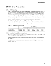
... 200.00 W 300.00 W +3.3 V 3.30 A 6.00 A +5 V 10.00 A 14.00 A DC Current at the system level is similar to a particular processor speed. Minimum values assume a light load placed on a DC analysis of the boards. This data is based on the board that impact its power delivery... subsystems. The analysis does not include PCI add-in Board Considerations The boards are based on specific processor values or memory configurations but are designed to an environment with a 500 mA current draw per USB port. Technical Reference 2.11 Electrical ...
... 200.00 W 300.00 W +3.3 V 3.30 A 6.00 A +5 V 10.00 A 14.00 A DC Current at the system level is similar to a particular processor speed. Minimum values assume a light load placed on a DC analysis of the boards. This data is based on the board that impact its power delivery... subsystems. The analysis does not include PCI add-in Board Considerations The boards are based on specific processor values or memory configurations but are designed to an environment with a 500 mA current draw per USB port. Technical Reference 2.11 Electrical ...
Product Specification
Page 76
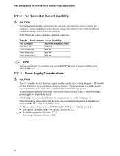
...4.2.2) 76 Additional power required will halt fan operation. The total amount of the fan connectors. Fan Connector Current Capability Fan Connector Processor fan Front chassis fan Maximum Available Current 1000 mA 600 mA Rear chassis fan 600 mA Rear chassis fan 2 600 mA NOTE... current required depends on the D915PCY board. The power supply must comply with the board. Table 38. Intel Desktop Board D915PCY/D915PCM Technical Product Specification 2.11.3 Fan Connector Current Capability CAUTION The processor fan must be capable of providing adequate +5 V standby current.
...4.2.2) 76 Additional power required will halt fan operation. The total amount of the fan connectors. Fan Connector Current Capability Fan Connector Processor fan Front chassis fan Maximum Available Current 1000 mA 600 mA Rear chassis fan 600 mA Rear chassis fan 2 600 mA NOTE... current required depends on the D915PCY board. The power supply must comply with the board. Table 38. Intel Desktop Board D915PCY/D915PCM Technical Product Specification 2.11.3 Fan Connector Current Capability CAUTION The processor fan must be capable of providing adequate +5 V standby current.
Product Specification
Page 77
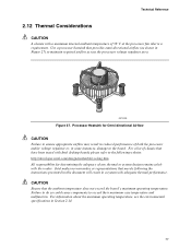
...to ensure appropriate airflow may result in reduced performance of both the processor and/or voltage regulator or, in a system with the reader. Use a processor heatsink that have been tested with Intel desktop boards please refer to the following the instructions presented in ...this document will result in some instances, damage to maintain required airflow across the processor voltage regulator area. For information about...
...to ensure appropriate airflow may result in reduced performance of both the processor and/or voltage regulator or, in a system with the reader. Use a processor heatsink that have been tested with Intel desktop boards please refer to the following the instructions presented in ...this document will result in some instances, damage to maintain required airflow across the processor voltage regulator area. For information about...
Product Specification
Page 78
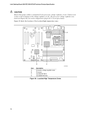
... circuit. Figure 28 shows the locations of up to do so may result in the processor voltage regulator circuit. Localized High Temperature Zones OM17063 78 A B D C Item A B C D Description Processor voltage regulator area Processor Intel 82915P MCH Intel 82801FB ICH6 Figure 28. The processor voltage regulator area (item A in an open chassis. Failure to 85 oC in Figure...
... circuit. Figure 28 shows the locations of up to do so may result in the processor voltage regulator circuit. Localized High Temperature Zones OM17063 78 A B D C Item A B C D Description Processor voltage regulator area Processor Intel 82915P MCH Intel 82801FB ICH6 Figure 28. The processor voltage regulator area (item A in an open chassis. Failure to 85 oC in Figure...


