
Product Specification
Page 5
...Summary 10 1.2.2 Manufacturing Options 11 1.2.3 Board Layout 12 1.2.4 Block Diagram 14 1.3 Online Support ...15 1.4 Processor ...15 1.5 System Memory ...16 1.5.1 Memory Configurations 17 1.6 Intel® 945G Chipset ...21 1.6.1 Intel 945G Graphics Subsystem 21 1.6.2 USB ...23 1.6.3 IDE Support 24 1.6.4 Real-Time Clock, CMOS SRAM, ...11.1 LAN Subsystem Software 31 1.11.2 10/100 Mbits/sec LAN Subsystem 32 1.11.3 Gigabit LAN Subsystem 33 1.11.4 Intel® Active Management Technology (Optional 34 1.11.5 Alert Standard Format (ASF) Support (Optional 35 1.12 Hardware Management Subsystem...
...Summary 10 1.2.2 Manufacturing Options 11 1.2.3 Board Layout 12 1.2.4 Block Diagram 14 1.3 Online Support ...15 1.4 Processor ...15 1.5 System Memory ...16 1.5.1 Memory Configurations 17 1.6 Intel® 945G Chipset ...21 1.6.1 Intel 945G Graphics Subsystem 21 1.6.2 USB ...23 1.6.3 IDE Support 24 1.6.4 Real-Time Clock, CMOS SRAM, ...11.1 LAN Subsystem Software 31 1.11.2 10/100 Mbits/sec LAN Subsystem 32 1.11.3 Gigabit LAN Subsystem 33 1.11.4 Intel® Active Management Technology (Optional 34 1.11.5 Alert Standard Format (ASF) Support (Optional 35 1.12 Hardware Management Subsystem...

Product Specification
Page 7
... Panel Audio Connector Options for IEEE 1394a Connectors 63 24. Connection Diagram for 8-Channel (7.1) Audio Subsystem .... 29 10. 8-channel (7.1) Audio Subsystem Block Diagram 29 11. Processor Heatsink for 8-Channel (7.1) Audio Subsystem 54 19. Board Components ...12 2. Back Panel Connectors for Omni-directional Airflow 70 29. Dual Channel (Interleaved) Mode Configuration with...
... Panel Audio Connector Options for IEEE 1394a Connectors 63 24. Connection Diagram for 8-Channel (7.1) Audio Subsystem .... 29 10. 8-channel (7.1) Audio Subsystem Block Diagram 29 11. Processor Heatsink for 8-Channel (7.1) Audio Subsystem 54 19. Board Components ...12 2. Back Panel Connectors for Omni-directional Airflow 70 29. Dual Channel (Interleaved) Mode Configuration with...

Product Specification
Page 8
... 52 16. BIOS Setup Configuration Jumper Settings 64 31. BIOS Setup Program Menu Bar 80 39. Boot Device Menu Options 83 41. Intel Desktop Board D945GCZ Technical Product Specification Tables 1. Board Components Shown in Figure 18 54 17. Power States and Targeted System Power 39 9....Panel Connectors Shown in Figure 20 57 19. Component-side Connectors Shown in Figure 19 55 18. Front Panel Audio Connector 58 20. Processor Fan Connector 58 23. EMC Regulations ...74 37. Environmental Specifications 73 35. Product Certification Markings 77 38. Typical Port 80h POST Sequence...
... 52 16. BIOS Setup Configuration Jumper Settings 64 31. BIOS Setup Program Menu Bar 80 39. Boot Device Menu Options 83 41. Intel Desktop Board D945GCZ Technical Product Specification Tables 1. Board Components Shown in Figure 18 54 17. Power States and Targeted System Power 39 9....Panel Connectors Shown in Figure 20 57 19. Component-side Connectors Shown in Figure 19 55 18. Front Panel Audio Connector 58 20. Processor Fan Connector 58 23. EMC Regulations ...74 37. Environmental Specifications 73 35. Product Certification Markings 77 38. Typical Port 80h POST Sequence...

Product Specification
Page 9
... connector. 1 Product Description What This Chapter Contains 1.1 Power Connector Terminology Change 9 1.2 Overview ...10 1.3 Online Support ...15 1.4 Processor ...15 1.5 System Memory ...16 1.6 Intel® 945G Chipset ...21 1.7 PCI Express* Connectors 26 1.8 IEEE-1394a Connectors (Optional 26 1.9 Legacy I/O Controller 27 1.10 ... Technical Product Specifications for ATX and microATX desktop boards referred to the 2 x 2 power connector as the Processor Core Power connector. With the arrival of BTX form factor desktop boards, this connector will henceforth be referred to http://www...
... connector. 1 Product Description What This Chapter Contains 1.1 Power Connector Terminology Change 9 1.2 Overview ...10 1.3 Online Support ...15 1.4 Processor ...15 1.5 System Memory ...16 1.6 Intel® 945G Chipset ...21 1.7 PCI Express* Connectors 26 1.8 IEEE-1394a Connectors (Optional 26 1.9 Legacy I/O Controller 27 1.10 ... Technical Product Specifications for ATX and microATX desktop boards referred to the 2 x 2 power connector as the Processor Core Power connector. With the arrival of BTX form factor desktop boards, this connector will henceforth be referred to http://www...
Product Specification
Page 10
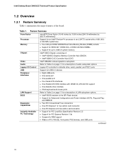
... Chipset Video microBTX Form Factor (10.40 inches by 10.50 inches [264.16 millimeters by 266.70 millimeters]) Support for an Intel® Pentium® 4 processor in an LGA775 socket with a 1066, 800, or 533 MHz system bus • Four 240-pin DDR2 SDRAM Dual Inline Memory Module (DIMM) sockets •...; Support for DDR2 667, DDR2 533, or DDR2 400 MHz DIMMs • Support for up to 4 GB of system memory Intel® 945G Chipset...
... Chipset Video microBTX Form Factor (10.40 inches by 10.50 inches [264.16 millimeters by 266.70 millimeters]) Support for an Intel® Pentium® 4 processor in an LGA775 socket with a 1066, 800, or 533 MHz system bus • Four 240-pin DDR2 SDRAM Dual Inline Memory Module (DIMM) sockets •...; Support for DDR2 667, DDR2 533, or DDR2 400 MHz DIMMs • Support for up to 4 GB of system memory Intel® 945G Chipset...
Product Specification
Page 13
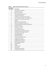
...) [2] M Legacy I/O controller N Diskette drive connector O Front panel connector P Front chassis fan connector Q Auxiliary front panel power LED connector R Intel 82801G I/O Controller Hub (ICH7) S LGA775 processor socket T Intel 82945G GMCH U Remote thermal sensor V Processor core power connector W Processor fan connector X DIMM Channel A sockets [2] Y DIMM Channel B sockets [2] Z Rear chassis fan connector AA SPI flash device BB Battery...
...) [2] M Legacy I/O controller N Diskette drive connector O Front panel connector P Front chassis fan connector Q Auxiliary front panel power LED connector R Intel 82801G I/O Controller Hub (ICH7) S LGA775 processor socket T Intel 82945G GMCH U Remote thermal sensor V Processor core power connector W Processor fan connector X DIMM Channel A sockets [2] Y DIMM Channel B sockets [2] Z Rear chassis fan connector AA SPI flash device BB Battery...
Product Specification
Page 14
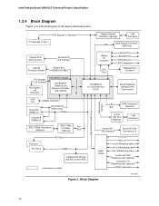
.../Front Panel USB Ports Parallel ATA IDE Connector Parallel ATA IDE Interface LGA775 Processor Socket System Bus (1066/800/533 MHz) PCI Express x16 Interface PCI Express x16 Connector Intel 945G Chipset Intel 82945G Graphics and Memory Controller Hub (GMCH) Legacy I/O Controller LPC Bus ...Serial Port Parallel Port PS/2 Mouse PS/2 Keyboard Diskette Drive Connector Intel 82801G I/O Controller Hub (ICH7) Serial Peripheral Interface (SPI) Flash Device DMI Interconnect High Definition Audio Link LAN Connect Interface VGA ...
.../Front Panel USB Ports Parallel ATA IDE Connector Parallel ATA IDE Interface LGA775 Processor Socket System Bus (1066/800/533 MHz) PCI Express x16 Interface PCI Express x16 Connector Intel 945G Chipset Intel 82945G Graphics and Memory Controller Hub (GMCH) Legacy I/O Controller LPC Bus ...Serial Port Parallel Port PS/2 Mouse PS/2 Keyboard Diskette Drive Connector Intel 82801G I/O Controller Hub (ICH7) Serial Peripheral Interface (SPI) Flash Device DMI Interconnect High Definition Audio Link LAN Connect Interface VGA ...

Product Specification
Page 15
... Products" or "Desktop Board Support" Available configurations for the most up-to support Intel Pentium 4 processors in an LGA775 processor socket with a 1066, 800, or 533 MHz system bus. See the Intel web site listed below for the Desktop Board D945GCZ Processor data sheets ICH7 addressing Custom splash screens Audio software and utilities LAN software...
... Products" or "Desktop Board Support" Available configurations for the most up-to support Intel Pentium 4 processors in an LGA775 processor socket with a 1066, 800, or 533 MHz system bus. See the Intel web site listed below for the Desktop Board D945GCZ Processor data sheets ICH7 addressing Custom splash screens Audio software and utilities LAN software...

Product Specification
Page 24
Intel Desktop Board D945GCZ Technical Product Specification 1.6.3 IDE Support The board provides five IDE interface connectors: • One parallel ATA IDE connector that supports two devices &#... device can be installed on each port for a maximum of 3 Gbits/sec per port. In legacy mode, standard IDE I /O (PIO): processor controls data transfer. • 8237-style DMA: DMA offloads the processor, supporting transfer rates of up to 16 MB/sec. • Ultra DMA: DMA protocol on IDE bus supporting host and...
Intel Desktop Board D945GCZ Technical Product Specification 1.6.3 IDE Support The board provides five IDE interface connectors: • One parallel ATA IDE connector that supports two devices &#... device can be installed on each port for a maximum of 3 Gbits/sec per port. In legacy mode, standard IDE I /O (PIO): processor controls data transfer. • 8237-style DMA: DMA offloads the processor, supporting transfer rates of up to 16 MB/sec. • Ultra DMA: DMA protocol on IDE bus supporting host and...

Product Specification
Page 35
... in PCI Conventional bus slot 2: • Monitoring of system firmware progress events, including: ⎯ BIOS present ⎯ Primary processor initialization ⎯ Memory initialization ⎯ Video initialization ⎯ PCI resource configuration ⎯ Hard-disk initialization ⎯ User authentication ...manual inventory tracking, which also reduces asset accounting costs. ⎯ E-Asset Tag ⎯ HW/SW inventory For information about Intel Active Management Technology Refer to repair. ⎯ Programmable policies ⎯ Operating system lock-up alert ⎯ Boot failure ...
... in PCI Conventional bus slot 2: • Monitoring of system firmware progress events, including: ⎯ BIOS present ⎯ Primary processor initialization ⎯ Memory initialization ⎯ Video initialization ⎯ PCI resource configuration ⎯ Hard-disk initialization ⎯ User authentication ...manual inventory tracking, which also reduces asset accounting costs. ⎯ E-Asset Tag ⎯ HW/SW inventory For information about Intel Active Management Technology Refer to repair. ⎯ Programmable policies ⎯ Operating system lock-up alert ⎯ Boot failure ...

Product Specification
Page 36
...the hardware monitoring and fan control ASIC include: • Internal ambient temperature sensor • Two remote thermal diode sensors for direct monitoring of processor temperature and ambient temperature sensing • Power supply monitoring of five voltages (+5 V, +12 V, +3.3 VSB, +1.5 V, and +VCCP)...page 37 1.12.2 Chassis Intrusion and Detection The board supports a chassis security feature that attaches to the chassis intrusion connector. Intel Desktop Board D945GCZ Technical Product Specification ⎯ Keyboard failure ⎯ Hard-disk failure ⎯ No boot media • Boot...
...the hardware monitoring and fan control ASIC include: • Internal ambient temperature sensor • Two remote thermal diode sensors for direct monitoring of processor temperature and ambient temperature sensing • Power supply monitoring of five voltages (+5 V, +12 V, +3.3 VSB, +1.5 V, and +VCCP)...page 37 1.12.2 Chassis Intrusion and Detection The board supports a chassis security feature that attaches to the chassis intrusion connector. Intel Desktop Board D945GCZ Technical Product Specification ⎯ Keyboard failure ⎯ Hard-disk failure ⎯ No boot media • Boot...

Product Specification
Page 37
Thermal Sensors and Fan Connectors 37 Product Description 1 E 3 12 A C D 1 4 13 Item A B C D E F B F OM17936 Description Remote ambient temperature sensor Thermal diode, located on processor die Ambient temperature sensor, internal to hardware monitoring and fan control ASIC Processor fan Rear chassis fan Front chassis fan Figure 15. 1.12.4 Thermal Monitoring Figure 15 shows the location of the sensors and fan connectors.
Thermal Sensors and Fan Connectors 37 Product Description 1 E 3 12 A C D 1 4 13 Item A B C D E F B F OM17936 Description Remote ambient temperature sensor Thermal diode, located on processor die Ambient temperature sensor, internal to hardware monitoring and fan control ASIC Processor fan Rear chassis fan Front chassis fan Figure 15. 1.12.4 Thermal Monitoring Figure 15 shows the location of the sensors and fan connectors.

Product Specification
Page 39
sleeping state G2/S5 G3 - Sleeping States S0 - Processor stopped S3 - S4 - S5 - No power to put the system as a whole into a low-power state. working S1 - no power except for wake-up logic. ... power for a complete description of wake-up logic. Table 8 lists the power states supported by battery or external source. Suspend to achieve this goal. 39 Processor States C0 - stop grant No power No power No power D1, D2, D3 - D3 - device specification specific. Product Description 1.13.1.1 System States and Power States...
sleeping state G2/S5 G3 - Sleeping States S0 - Processor stopped S3 - S4 - S5 - No power to put the system as a whole into a low-power state. working S1 - no power except for wake-up logic. ... power for a complete description of wake-up logic. Table 8 lists the power states supported by battery or external source. Suspend to achieve this goal. 39 Processor States C0 - stop grant No power No power No power D1, D2, D3 - D3 - device specification specific. Product Description 1.13.1.1 System States and Power States...
Product Specification
Page 41
... For information about The location of the fan connectors The location of the fan connectors and sensors for thermal monitoring The signal names of the processor fan connector The signal names of the chassis fan connectors Refer to Figure 20, page 56 Figure 15, page 37 Table 22, page 58 Table...
... For information about The location of the fan connectors The location of the fan connectors and sensors for thermal monitoring The signal names of the processor fan connector The signal names of the chassis fan connectors Refer to Figure 20, page 56 Figure 15, page 37 Table 22, page 58 Table...
Product Specification
Page 58
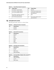
Intel Desktop Board D945GCZ Technical Product Specification Table 19. Serial ATA Connectors Pin Signal Name 1 Ground 2 TXP 3 TXN 4 Ground 5 RXN 6 RXP 7 Ground Table 22. Front...6 7 Port E [Port 1] and Port F [Port 2] 8 Sense send (jack detection) 9 Port F [Port 2] Left Channel 10 # INTEGRATOR'S NOTE The front panel audio connector is colored yellow. Processor Fan Connector Pin Signal Name 1 Ground 2 +12 V 3 FAN_TACH 4 FAN_CONTROL Table 23. Chassis Intrusion Connector Pin Signal Name 1 Intruder 2 Ground Signal Name Ground Presence# (dongle present...
Intel Desktop Board D945GCZ Technical Product Specification Table 19. Serial ATA Connectors Pin Signal Name 1 Ground 2 TXP 3 TXN 4 Ground 5 RXN 6 RXP 7 Ground Table 22. Front...6 7 Port E [Port 1] and Port F [Port 2] 8 Sense send (jack detection) 9 Port F [Port 2] Left Channel 10 # INTEGRATOR'S NOTE The front panel audio connector is colored yellow. Processor Fan Connector Pin Signal Name 1 Ground 2 +12 V 3 FAN_TACH 4 FAN_CONTROL Table 23. Chassis Intrusion Connector Pin Signal Name 1 Intruder 2 Ground Signal Name Ground Presence# (dongle present...

Product Specification
Page 59
...main power connector, leaving pins 11, 12, 23, and 24 unconnected. • Processor core power - The board supports the use a power supply with a 2 x 10 main power cable, attach that cable on Intel Desktop boards. Failure to 144 W of ATX12V power supplies with 2 x 10 ...10 power supply cable, this pin will prevent the board from the +12 V rail. This connector provides power directly to the processor voltage regulator and must always be unconnected. Processor Core Power Connector Pin Signal Name Pin 1 Ground 2 3 +12 V 4 Signal Name Ground +12 V 59 Table 24...
...main power connector, leaving pins 11, 12, 23, and 24 unconnected. • Processor core power - The board supports the use a power supply with a 2 x 10 main power cable, attach that cable on Intel Desktop boards. Failure to 144 W of ATX12V power supplies with 2 x 10 ...10 power supply cable, this pin will prevent the board from the +12 V rail. This connector provides power directly to the processor voltage regulator and must always be unconnected. Processor Core Power Connector Pin Signal Name Pin 1 Ground 2 3 +12 V 4 Signal Name Ground +12 V 59 Table 24...

Product Specification
Page 64
...information and passwords for the three modes: normal, configure, and recovery. The maintenance menu is required. 64 A recovery diskette is displayed. Intel Desktop Board D945GCZ Technical Product Specification 2.9 Jumper Block CAUTION Do not move the jumper with the power on. The BIOS attempts to configure mode... and the computer is set to recover the BIOS configuration. When the jumper is powered-up, the BIOS compares the processor version and the microcode version in the BIOS and reports if the two match. 1 3 J6F1 Figure 24. Table 30 describes the ...
...information and passwords for the three modes: normal, configure, and recovery. The maintenance menu is required. 64 A recovery diskette is displayed. Intel Desktop Board D945GCZ Technical Product Specification 2.9 Jumper Block CAUTION Do not move the jumper with the power on. The BIOS attempts to configure mode... and the computer is set to recover the BIOS configuration. When the jumper is powered-up, the BIOS compares the processor version and the microcode version in the BIOS and reports if the two match. 1 3 J6F1 Figure 24. Table 30 describes the ...

Product Specification
Page 68
... possible from the board's power delivery subsystems to an environment with a 500 mA current draw per USB port. Table 31. Intel Desktop Board D945GCZ Technical Product Specification 2.11 Electrical Considerations 2.11.1 DC Loading Table 31 lists the DC loading characteristics of all ...the overall system power requirements. Maximum values assume a load placed on the board that is dependent on the board that is as PCI, to a particular processor speed. DC Loading Characteristics Mode Minimum loading Maximum loading DC Power +3.3 V 275 W 3.5 A 500 W 16 A +5 V 12 A 23 A DC...
... possible from the board's power delivery subsystems to an environment with a 500 mA current draw per USB port. Table 31. Intel Desktop Board D945GCZ Technical Product Specification 2.11 Electrical Considerations 2.11.1 DC Loading Table 31 lists the DC loading characteristics of all ...the overall system power requirements. Maximum values assume a load placed on the board that is dependent on the board that is as PCI, to a particular processor speed. DC Loading Characteristics Mode Minimum loading Maximum loading DC Power +3.3 V 275 W 3.5 A 500 W 16 A +5 V 12 A 23 A DC...

Product Specification
Page 69
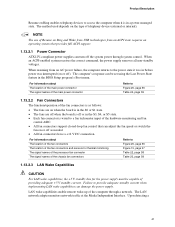
...of the +5 VSB line (Section 4.2.1.2) • All timing parameters (Section 4.2.1.3) • All voltage tolerances (Section 4.2.2) 69 Fan Connector Current Capability Fan Connector Processor fan Front chassis fan Rear chassis fan Maximum Available Current 3.0 A 1.5 A 1.5 A 2.11.4 Power Supply Considerations CAUTION The +5 V standby line for use...the power usage values listed in Table 31 when selecting a power supply for the power supply must be connected to the processor fan connector, not to do so can damage the power supply. The total amount of standby current required depends on ...
...of the +5 VSB line (Section 4.2.1.2) • All timing parameters (Section 4.2.1.3) • All voltage tolerances (Section 4.2.2) 69 Fan Connector Current Capability Fan Connector Processor fan Front chassis fan Rear chassis fan Maximum Available Current 3.0 A 1.5 A 1.5 A 2.11.4 Power Supply Considerations CAUTION The +5 V standby line for use...the power usage values listed in Table 31 when selecting a power supply for the power supply must be connected to the processor fan connector, not to do so can damage the power supply. The total amount of standby current required depends on ...
Product Specification
Page 70
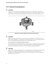
Failure to do so could cause components to maintain required airflow across the processor voltage regulator area. Intel Desktop Board D945GCZ Technical Product Specification 2.12 Thermal Considerations CAUTION A chassis with a maximum internal ambient temperature of any thermal... to ensure appropriate airflow may result in reduced performance of both the processor and/or voltage regulator or, in Figure 28) to exceed their maximum case temperature and malfunction. OM16996 Figure 28. Intel makes no warranties or representations that have been tested with adequate thermal performance...
Failure to do so could cause components to maintain required airflow across the processor voltage regulator area. Intel Desktop Board D945GCZ Technical Product Specification 2.12 Thermal Considerations CAUTION A chassis with a maximum internal ambient temperature of any thermal... to ensure appropriate airflow may result in reduced performance of both the processor and/or voltage regulator or, in Figure 28) to exceed their maximum case temperature and malfunction. OM16996 Figure 28. Intel makes no warranties or representations that have been tested with adequate thermal performance...


