Product Specification
Page 5
...Summary 10 1.1.2 Manufacturing Options 11 1.1.3 Board Layout 12 1.1.4 Block Diagram 14 1.2 Online Support ...15 1.3 Processor ...15 1.4 System Memory ...16 1.4.1 Memory Configurations 17 1.5 Intel® 945G Chipset ...21 1.5.1 Intel 945G Graphics Subsystem 21 1.5.2 USB ...23 1.5.3 IDE Support 24 1.5.4 Real-Time Clock, CMOS SRAM, ...10.1 LAN Subsystem Software 32 1.10.2 10/100 Mbits/sec LAN Subsystem 32 1.10.3 Gigabit LAN Subsystem 33 1.10.4 Intel® Active Management Technology (Optional 34 1.10.5 Alert Standard Format (ASF) Support (Optional 36 1.11 Hardware Management Subsystem...
...Summary 10 1.1.2 Manufacturing Options 11 1.1.3 Board Layout 12 1.1.4 Block Diagram 14 1.2 Online Support ...15 1.3 Processor ...15 1.4 System Memory ...16 1.4.1 Memory Configurations 17 1.5 Intel® 945G Chipset ...21 1.5.1 Intel 945G Graphics Subsystem 21 1.5.2 USB ...23 1.5.3 IDE Support 24 1.5.4 Real-Time Clock, CMOS SRAM, ...10.1 LAN Subsystem Software 32 1.10.2 10/100 Mbits/sec LAN Subsystem 32 1.10.3 Gigabit LAN Subsystem 33 1.10.4 Intel® Active Management Technology (Optional 34 1.10.5 Alert Standard Format (ASF) Support (Optional 36 1.11 Hardware Management Subsystem...
Product Specification
Page 7
... 20 8. Location of the Jumper Block 67 25. Detailed System Memory Address Map 48 18. Back Panel Connectors for Front Panel USB Connectors 66 23. Processor Heatsink for Front Panel Connector 64 22. Supported Memory Configurations 16 5. Block Diagram...14 3. LAN Connector LED Locations 34 15. Board Components Shown in Figure...
... 20 8. Location of the Jumper Block 67 25. Detailed System Memory Address Map 48 18. Back Panel Connectors for Front Panel USB Connectors 66 23. Processor Heatsink for Front Panel Connector 64 22. Supported Memory Configurations 16 5. Block Diagram...14 3. LAN Connector LED Locations 34 15. Board Components Shown in Figure...

Product Specification
Page 8
... LED Connector 63 29. Port 80h POST Code Ranges 90 47. PCI Configuration Space Map 51 14. Processor Fan Connector 61 24. States for a One-Color Power LED 65 31. System Memory Map 49 11. Intel Desktop Board D945GNT Technical Product Specification 6. SCSI Hard Drive Activity LED Connector (Optional 60 22. Auxiliary...
... LED Connector 63 29. Port 80h POST Code Ranges 90 47. PCI Configuration Space Map 51 14. Processor Fan Connector 61 24. States for a One-Color Power LED 65 31. System Memory Map 49 11. Intel Desktop Board D945GNT Technical Product Specification 6. SCSI Hard Drive Activity LED Connector (Optional 60 22. Auxiliary...
Product Specification
Page 9
1 Product Description What This Chapter Contains 1.1 Overview ...10 1.2 Online Support ...15 1.3 Processor ...15 1.4 System Memory ...16 1.5 Intel® 945G Chipset ...21 1.6 PCI Express Connectors 26 1.7 IEEE-1394a Connectors (Optional 26 1.8 Legacy I/O Controller 27 1.9 Audio Subsystem ...28 1.10 LAN Subsystem ...32 1.11 Hardware Management Subsystem 36 1.12 Power Management ...39 1.13 Trusted Platform Module (Optional 45 9
1 Product Description What This Chapter Contains 1.1 Overview ...10 1.2 Online Support ...15 1.3 Processor ...15 1.4 System Memory ...16 1.5 Intel® 945G Chipset ...21 1.6 PCI Express Connectors 26 1.7 IEEE-1394a Connectors (Optional 26 1.8 Legacy I/O Controller 27 1.9 Audio Subsystem ...28 1.10 LAN Subsystem ...32 1.11 Hardware Management Subsystem 36 1.12 Power Management ...39 1.13 Trusted Platform Module (Optional 45 9
Product Specification
Page 10
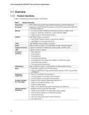
...Summary Form Factor ATX (12.00 inches by 9.60 inches [304.80 millimeters by 243.84 millimeters]) Processor Support for an Intel® Pentium® 4 processor in card connector Instantly Available PC Technology • Support for PCI Local Bus Specification Revision 2.3 •...Control Legacy I/O controller for diskette drive, serial, parallel, and PS/2* ports USB Support for a description of LAN subsystem options. Intel Desktop Board D945GNT Technical Product Specification 1.1 Overview 1.1.1 Feature Summary Table 1 summarizes the major features of range thermal values • ...
...Summary Form Factor ATX (12.00 inches by 9.60 inches [304.80 millimeters by 243.84 millimeters]) Processor Support for an Intel® Pentium® 4 processor in card connector Instantly Available PC Technology • Support for PCI Local Bus Specification Revision 2.3 •...Control Legacy I/O controller for diskette drive, serial, parallel, and PS/2* ports USB Support for a description of LAN subsystem options. Intel Desktop Board D945GNT Technical Product Specification 1.1 Overview 1.1.1 Feature Summary Table 1 summarizes the major features of range thermal values • ...
Product Specification
Page 14
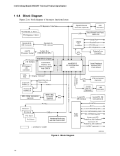
... PCI Express x1 Slot 1 PCI Express x1 Slot 2 Parallel ATA IDE Connector Parallel ATA IDE Interface LGA775 Processor Socket System Bus (1066/800/533 MHz) PCI Express x16 Interface PCI Express x16 Connector Intel 945G Chipset Intel 82945G Graphics and Memory Controller Hub (GMCH) Gigabit Ethernet Controller (Optional) LAN Connector USB Back Panel...
... PCI Express x1 Slot 1 PCI Express x1 Slot 2 Parallel ATA IDE Connector Parallel ATA IDE Interface LGA775 Processor Socket System Bus (1066/800/533 MHz) PCI Express x16 Interface PCI Express x16 Connector Intel 945G Chipset Intel 82945G Graphics and Memory Controller Hub (GMCH) Gigabit Ethernet Controller (Optional) LAN Connector USB Back Panel...
Product Specification
Page 15
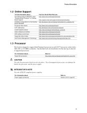
... 2.8.2.2, page 62 15 Product Description 1.2 Online Support To find information about ... Use of supported processors. Intel Desktop Board D945GNT under "Desktop Board Products" or "Desktop Board Support" Available configurations for the most up-to support Intel Pentium 4 processors in an LGA775 processor socket with a 1066, 800, or 533 MHz system bus. For information about ... For...
... 2.8.2.2, page 62 15 Product Description 1.2 Online Support To find information about ... Use of supported processors. Intel Desktop Board D945GNT under "Desktop Board Products" or "Desktop Board Support" Available configurations for the most up-to support Intel Pentium 4 processors in an LGA775 processor socket with a 1066, 800, or 533 MHz system bus. For information about ... For...

Product Specification
Page 24
...throttling and transfer rates of four Serial ATA devices. In legacy mode, standard IDE I /O (PIO): processor controls data transfer. • 8237-style DMA: DMA offloads the processor, supporting transfer rates of up to 16 MB/sec. • Ultra DMA: DMA protocol on IDE bus...interface supports the following modes: • Programmed I /O and IRQ resources are faster timings and require a specialized cable to the BIOS. Intel Desktop Board D945GNT Technical Product Specification 1.5.3 IDE Support The board provides five IDE interface connectors: • One parallel ATA IDE connector that ...
...throttling and transfer rates of four Serial ATA devices. In legacy mode, standard IDE I /O (PIO): processor controls data transfer. • 8237-style DMA: DMA offloads the processor, supporting transfer rates of up to 16 MB/sec. • Ultra DMA: DMA protocol on IDE bus...interface supports the following modes: • Programmed I /O and IRQ resources are faster timings and require a specialized cable to the BIOS. Intel Desktop Board D945GNT Technical Product Specification 1.5.3 IDE Support The board provides five IDE interface connectors: • One parallel ATA IDE connector that ...
Product Specification
Page 36
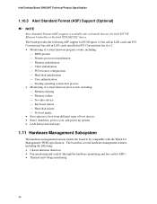
... in PCI Conventional bus slot 2: • Monitoring of system firmware progress events, including: ⎯ BIOS present ⎯ Primary processor initialization ⎯ Memory initialization ⎯ Video initialization ⎯ PCI resource configuration ⎯ Hard-disk initialization ⎯ User authentication ... Management Subsystem The hardware management features enable the board to be compatible with the Wired for Management (WfM) specification. Intel Desktop Board D945GNT Technical Product Specification 1.10.5 Alert Standard Format (ASF) Support (Optional) NOTE Alter Standard Format (...
... in PCI Conventional bus slot 2: • Monitoring of system firmware progress events, including: ⎯ BIOS present ⎯ Primary processor initialization ⎯ Memory initialization ⎯ Video initialization ⎯ PCI resource configuration ⎯ Hard-disk initialization ⎯ User authentication ... Management Subsystem The hardware management features enable the board to be compatible with the Wired for Management (WfM) specification. Intel Desktop Board D945GNT Technical Product Specification 1.10.5 Alert Standard Format (ASF) Support (Optional) NOTE Alter Standard Format (...
Product Specification
Page 37
...of the hardware monitoring and fan control ASIC include: • Internal ambient temperature sensor • Two remote thermal diode sensors for direct monitoring of processor temperature and ambient temperature sensing • Power supply monitoring of five voltages (+5 V, +12 V, +3.3 VSB, +1.5 V, and +VCCP) to ...page 38 1.11.2 Chassis Intrusion and Detection The board supports a chassis security feature that can be implemented using Intel® Desktop Utilities or third-party software. The security feature uses a mechanical switch on the hardware monitoring ASIC used with the ...
...of the hardware monitoring and fan control ASIC include: • Internal ambient temperature sensor • Two remote thermal diode sensors for direct monitoring of processor temperature and ambient temperature sensing • Power supply monitoring of five voltages (+5 V, +12 V, +3.3 VSB, +1.5 V, and +VCCP) to ...page 38 1.11.2 Chassis Intrusion and Detection The board supports a chassis security feature that can be implemented using Intel® Desktop Utilities or third-party software. The security feature uses a mechanical switch on the hardware monitoring ASIC used with the ...
Product Specification
Page 38
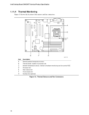
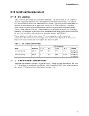
Thermal Sensors and Fan Connectors 38 Intel Desktop Board D945GNT Technical Product Specification 1.11.4 Thermal Monitoring Figure 15 shows the location of the sensors and fan connectors. 4 1 1 3 A B C 4 1 D 13 Item A B C D E F G G F E OM17741 Description Remote ambient temperature sensor Thermal diode, located on processor die Ambient temperature sensor, internal to hardware monitoring and fan control ASIC Processor fan Rear chassis fan Front chassis fan Auxiliary fan (optional) Figure 15.
Thermal Sensors and Fan Connectors 38 Intel Desktop Board D945GNT Technical Product Specification 1.11.4 Thermal Monitoring Figure 15 shows the location of the sensors and fan connectors. 4 1 1 3 A B C 4 1 D 13 Item A B C D E F G G F E OM17741 Description Remote ambient temperature sensor Thermal diode, located on processor die Ambient temperature sensor, internal to hardware monitoring and fan control ASIC Processor fan Rear chassis fan Front chassis fan Auxiliary fan (optional) Figure 15.
Product Specification
Page 40
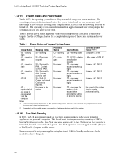
... used by the board along with the associated system power targets. Power States and Targeted System Power Global States Sleeping States Processor States Device States Targeted System Power (Note 1) G0 - no power for wake-up logic, except when provided by the...specification specific. 5 W < power < 52.5 W G1 - working state S0 - sleeping state G2/S5 S3 - S5 - Notes: 1. Intel Desktop Board D945GNT Technical Product Specification 1.12.1.1 System States and Power States Under ACPI, the operating system directs all system and device power state transitions...
... used by the board along with the associated system power targets. Power States and Targeted System Power Global States Sleeping States Processor States Device States Targeted System Power (Note 1) G0 - no power for wake-up logic, except when provided by the...specification specific. 5 W < power < 52.5 W G1 - working state S0 - sleeping state G2/S5 S3 - S5 - Notes: 1. Intel Desktop Board D945GNT Technical Product Specification 1.12.1.1 System States and Power States Under ACPI, the operating system directs all system and device power state transitions...
Product Specification
Page 42
The LAN network adapter monitors network traffic at the Media Independent Interface. Intel Desktop Board D945GNT Technical Product Specification NOTE The use of Resume on Ring and Wake from USB technologies from an AC power failure, the computer .... For information about The location of the fan connectors The location of the fan connectors and sensors for thermal monitoring The signal names of the processor fan connector The signal names of providing adequate +5 V standby current. Failure to Figure 20, page 58 Figure 15, page 38 Table 23, page 61 Table...
The LAN network adapter monitors network traffic at the Media Independent Interface. Intel Desktop Board D945GNT Technical Product Specification NOTE The use of Resume on Ring and Wake from USB technologies from an AC power failure, the computer .... For information about The location of the fan connectors The location of the fan connectors and sensors for thermal monitoring The signal names of the processor fan connector The signal names of providing adequate +5 V standby current. Failure to Figure 20, page 58 Figure 15, page 38 Table 23, page 61 Table...
Product Specification
Page 61
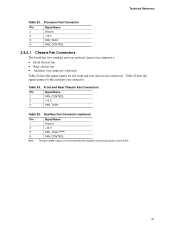
Processor Fan Connector Pin Signal Name 1 Ground 2 +12 V 3 FAN_TACH 4 FAN_CONTROL 2.8.2.1 Chassis Fan Connectors The board has two standard and one optional chassis fan connectors: • Front ...
Processor Fan Connector Pin Signal Name 1 Ground 2 +12 V 3 FAN_TACH 4 FAN_CONTROL 2.8.2.1 Chassis Fan Connectors The board has two standard and one optional chassis fan connectors: • Front ...
Product Specification
Page 62
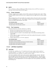
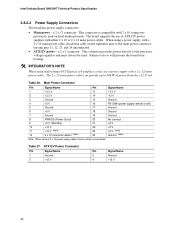
...with 2 x 10 connectors previously used . ATX12V Power Connector Pin Signal Name 1 Ground 3 +12 V Pin Signal Name 2 Ground 4 +12 V 62 Intel Desktop Board D945GNT Technical Product Specification 2.8.2.2 Power Supply Connectors The board has power supply connectors: • Main power - The 2 x 12 main power cable... can provide up to the processor voltage regulator and must always be unconnected. This connector provides power directly to 144 W of the main power connector, leaving pins 11...
...with 2 x 10 connectors previously used . ATX12V Power Connector Pin Signal Name 1 Ground 3 +12 V Pin Signal Name 2 Ground 4 +12 V 62 Intel Desktop Board D945GNT Technical Product Specification 2.8.2.2 Power Supply Connectors The board has power supply connectors: • Main power - The 2 x 12 main power cable... can provide up to the processor voltage regulator and must always be unconnected. This connector provides power directly to 144 W of the main power connector, leaving pins 11...
Product Specification
Page 67
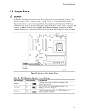
..., configure, and recovery. A 1 recovery diskette is displayed. Recovery None 3 The BIOS attempts to configure mode and the computer is powered-up, the BIOS compares the processor version and the microcode version in the BIOS and reports if the two match. 31 J7J3 Figure 24. Technical Reference 2.9 Jumper Block CAUTION Do not...
..., configure, and recovery. A 1 recovery diskette is displayed. Recovery None 3 The BIOS attempts to configure mode and the computer is powered-up, the BIOS compares the processor version and the microcode version in the BIOS and reports if the two match. 31 J7J3 Figure 24. Technical Reference 2.9 Jumper Block CAUTION Do not...
Product Specification
Page 71
...power delivery subsystems. The analysis does not include PCI add-in cards, such as PCI, to a particular processor speed. These calculations are not based on specific processor values or memory configurations but are designed to an environment with a 500 mA current draw per USB port. ...(S3) 0.34 A (S0) 1.10 A (S3) 2.11.2 Add-in Board Considerations The boards are based on the board that is similar to the processor, memory, and USB ports. Maximum values assume a load placed on the minimum and maximum current draw possible from the board's power delivery subsystems to a heavy...
...power delivery subsystems. The analysis does not include PCI add-in cards, such as PCI, to a particular processor speed. These calculations are not based on specific processor values or memory configurations but are designed to an environment with a 500 mA current draw per USB port. ...(S3) 0.34 A (S0) 1.10 A (S3) 2.11.2 Add-in Board Considerations The boards are based on the board that is similar to the processor, memory, and USB ports. Maximum values assume a load placed on the minimum and maximum current draw possible from the board's power delivery subsystems to a heavy...
Product Specification
Page 72
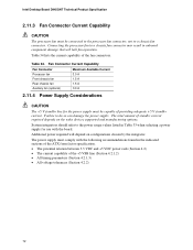
...of standby current required depends on configurations chosen by the integrator. Fan Connector Current Capability Fan Connector Processor fan Front chassis fan Rear chassis fan Auxiliary fan (optional) Maximum Available Current 3.0 A 1.5 A... Supply Considerations CAUTION The +5 V standby line for the power supply must be connected to the processor fan connector, not to the power usage values listed in Table 33 when selecting a power supply... depend on the wake devices supported and manufacturing options. Connecting the processor fan to do so can damage the power supply. Table 34 ...
...of standby current required depends on configurations chosen by the integrator. Fan Connector Current Capability Fan Connector Processor fan Front chassis fan Rear chassis fan Auxiliary fan (optional) Maximum Available Current 3.0 A 1.5 A... Supply Considerations CAUTION The +5 V standby line for the power supply must be connected to the processor fan connector, not to the power usage values listed in Table 33 when selecting a power supply... depend on the wake devices supported and manufacturing options. Connecting the processor fan to do so can damage the power supply. Table 34 ...
Product Specification
Page 73
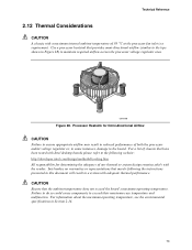
... will result in a system with adequate thermal performance. Intel makes no warranties or representations that have been tested with Intel desktop boards please refer to maintain required airflow across the processor voltage regulator area. For information about the maximum operating ...temperature, see the environmental specifications in Section 2.14. 73 Processor Heatsink for determining the adequacy of chassis that merely following website: http://developer.intel.com/design/motherbd/cooling.htm All responsibility for Omni-directional Airflow CAUTION Failure...
... will result in a system with adequate thermal performance. Intel makes no warranties or representations that have been tested with Intel desktop boards please refer to maintain required airflow across the processor voltage regulator area. For information about the maximum operating ...temperature, see the environmental specifications in Section 2.14. 73 Processor Heatsink for determining the adequacy of chassis that merely following website: http://developer.intel.com/design/motherbd/cooling.htm All responsibility for Omni-directional Airflow CAUTION Failure...
Product Specification
Page 74
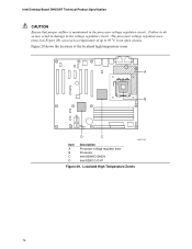
... regulator area (item A in Figure 29) can reach a temperature of the localized high temperature zones. A B D C OM17742 Item A B C D Description Processor voltage regulator area Processor Intel 82945G GMCH Intel 82801G ICH7 Figure 29. Intel Desktop Board D945GNT Technical Product Specification CAUTION Ensure that proper airflow is maintained in an open chassis. Failure to do so may result...
... regulator area (item A in Figure 29) can reach a temperature of the localized high temperature zones. A B D C OM17742 Item A B C D Description Processor voltage regulator area Processor Intel 82945G GMCH Intel 82801G ICH7 Figure 29. Intel Desktop Board D945GNT Technical Product Specification CAUTION Ensure that proper airflow is maintained in an open chassis. Failure to do so may result...


