Product Guide
Page 6
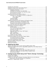
...Alternate Front Panel Power LED Header 53 USB 2.0 Headers 53 IEEE 1394a Header 54 Chassis Intrusion Header 54 Connecting to the Audio System 55 Connecting Chassis Fan and Power Supply Cables 56 Connecting Chassis Fan Cables 56 Connecting Power Supply Cables 57 Connecting the Bluetooth Antenna 58 ...Setting the BIOS Configuration Jumper 59 Clearing Passwords 60 Replacing the Battery 61 3 Updating the BIOS Updating the BIOS with the Intel® Express BIOS Update Utility 67 Updating the BIOS with the ISO Image BIOS Update File or the Iflash Memory Update Utility 68 ...
...Alternate Front Panel Power LED Header 53 USB 2.0 Headers 53 IEEE 1394a Header 54 Chassis Intrusion Header 54 Connecting to the Audio System 55 Connecting Chassis Fan and Power Supply Cables 56 Connecting Chassis Fan Cables 56 Connecting Power Supply Cables 57 Connecting the Bluetooth Antenna 58 ...Setting the BIOS Configuration Jumper 59 Clearing Passwords 60 Replacing the Battery 61 3 Updating the BIOS Updating the BIOS with the Intel® Express BIOS Update Utility 67 Updating the BIOS with the ISO Image BIOS Update File or the Iflash Memory Update Utility 68 ...

Product Guide
Page 8
...90 viii S/PDIF Header Signal Names 51 5. Lead-Free Second Level Interconnect Marks 85 20. EMC Regulations 88 22. Back Panel Audio Connectors 55 29. Front Panel CIR Receiver (Input) Header Signal Names 52 7. Jumper Settings for the BIOS Setup Program Modes 60 14. Front Panel... 51 6. Alternate Front Panel Power LED Header Signal Names 53 10. Location of the Chassis Fan Headers 56 30. Removing the Battery 66 34. Intel Desktop Board DP55KG Components 13 3. Chassis Intrusion Header Signal Names 54 13. BIOS Error Messages 74 17. Front Panel Header Signal Names 52 9. BIOS...
...90 viii S/PDIF Header Signal Names 51 5. Lead-Free Second Level Interconnect Marks 85 20. EMC Regulations 88 22. Back Panel Audio Connectors 55 29. Front Panel CIR Receiver (Input) Header Signal Names 52 7. Jumper Settings for the BIOS Setup Program Modes 60 14. Front Panel... 51 6. Alternate Front Panel Power LED Header Signal Names 53 10. Location of the Chassis Fan Headers 56 30. Removing the Battery 66 34. Intel Desktop Board DP55KG Components 13 3. Chassis Intrusion Header Signal Names 54 13. BIOS Error Messages 74 17. Front Panel Header Signal Names 52 9. BIOS...

Product Guide
Page 55
Back Panel Audio Connectors NOTE The back panel line out connector is designed to the Audio System After installing the Realtek audio driver from the Intel® Express Installer DVD-ROM, the multi-channel audio feature can be enabled. Installing and Replacing Desktop Board Components Connecting to power either headphones or ... Jack D Line Out E Mic In F Side Surround Figure 28. Figure 28 shows the back panel audio connectors. The connector assignments are connected to this output. 55
Back Panel Audio Connectors NOTE The back panel line out connector is designed to the Audio System After installing the Realtek audio driver from the Intel® Express Installer DVD-ROM, the multi-channel audio feature can be enabled. Installing and Replacing Desktop Board Components Connecting to power either headphones or ... Jack D Line Out E Mic In F Side Surround Figure 28. Figure 28 shows the back panel audio connectors. The connector assignments are connected to this output. 55