Product Guide
Page 4
Intel Desktop Boards D850MD and D850MV Product Guide Installing and Removing an AGP Card Retention Mechanism and Card 32 Installing the AGP Card Retention Mechanism 32 Installing an AGP Card 34 Removing the AGP Card from the Retention Mechanism 34 Removing the AGP Card Retention Mechanism 35 Connecting... APM Submenu ...62 ACPI Submenu...62 Boot Menu...63 Boot Device Priority 63 Exit Menu ...64 5 Technical Reference Board Connectors ...65 Back Panel Connectors 66 Midboard Connectors 67 Audio Connectors 67 Power and Hardware Connectors 68 Add-In Card and Peripheral Interface Connectors ...
Intel Desktop Boards D850MD and D850MV Product Guide Installing and Removing an AGP Card Retention Mechanism and Card 32 Installing the AGP Card Retention Mechanism 32 Installing an AGP Card 34 Removing the AGP Card from the Retention Mechanism 34 Removing the AGP Card Retention Mechanism 35 Connecting... APM Submenu ...62 ACPI Submenu...62 Boot Menu...63 Boot Device Priority 63 Exit Menu ...64 5 Technical Reference Board Connectors ...65 Back Panel Connectors 66 Midboard Connectors 67 Audio Connectors 67 Power and Hardware Connectors 68 Add-In Card and Peripheral Interface Connectors ...

Product Guide
Page 5
...Audio Connectors ...67 23. Connecting the Processor Fan Cable to the Board 26 9. RIMM Installation ...30 13. AGP Card with a Retention Notch 32 15. Connecting the IDE Cable 36 19. Location of Standby Power Indicator 19 4. D850MD Board Power and Hardware Control ...17. Contents Desktop Board Resources 73 Memory Map ...73 DMA Channels ...73 I /O Shield 22 5. D850MD Board Add-in Card and Peripheral Interface Connectors 70 v D850MV Board Components 10 3. RDRAM and CRIMM Installation 29 12. Removing the Battery 41 21. Back Panel Connectors 66 22. D850MD Board Components 9...
...Audio Connectors ...67 23. Connecting the Processor Fan Cable to the Board 26 9. RIMM Installation ...30 13. AGP Card with a Retention Notch 32 15. Connecting the IDE Cable 36 19. Location of Standby Power Indicator 19 4. D850MD Board Power and Hardware Control ...17. Contents Desktop Board Resources 73 Memory Map ...73 DMA Channels ...73 I /O Shield 22 5. D850MD Board Add-in Card and Peripheral Interface Connectors 70 v D850MV Board Components 10 3. RDRAM and CRIMM Installation 29 12. Removing the Battery 41 21. Back Panel Connectors 66 22. D850MD Board Components 9...
Product Guide
Page 7
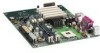
...Desktop Board Features ✏ NOTE The D850MD board layout was used for up to 2 GB of system memory Intel® 850 chipset, consisting of the D850MD and D850MV boards. Feature Summary Form Factors Processor Memory Chipset • microATX at 9.6 inches by 9.6 inches (D850MD board) • ATX at 9.6 inches by 12 inches (D850MV board) • Support for an Intel... • Intel® 82850 Memory Controller Hub (MCH) with Accelerated Hub Architecture (AHA) bus • Intel® 82801BA I /O controller LAN Optional Intel® 82562ET 10/100 Mbit/sec Platform LAN Connect (PLC) ...
...Desktop Board Features ✏ NOTE The D850MD board layout was used for up to 2 GB of system memory Intel® 850 chipset, consisting of the D850MD and D850MV boards. Feature Summary Form Factors Processor Memory Chipset • microATX at 9.6 inches by 9.6 inches (D850MD board) • ATX at 9.6 inches by 12 inches (D850MV board) • Support for an Intel... • Intel® 82850 Memory Controller Hub (MCH) with Accelerated Hub Architecture (AHA) bus • Intel® 82801BA I /O controller LAN Optional Intel® 82562ET 10/100 Mbit/sec Platform LAN Connect (PLC) ...
Product Guide
Page 14
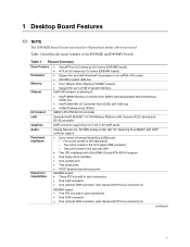
... cable. To attach additional devices, connect an external hub to either of standard software drivers written to the optional CNR. Intel Desktop Boards D850MD and D850MV Product Guide USB Support The boards suppport up to the computer without an external hub. four ports routed to the back panel, two to the front panel connector, and one to be...
... cable. To attach additional devices, connect an external hub to either of standard software drivers written to the optional CNR. Intel Desktop Boards D850MD and D850MV Product Guide USB Support The boards suppport up to the computer without an external hub. four ports routed to the back panel, two to the front panel connector, and one to be...
Product Guide
Page 15
An AGP card retention mechanism (RM) may occur if passive (non-amplified) speakers are available from Intel's World Wide Web site: http://support.intel.com/support/motherboards/desktop BIOS The BIOS provides the Power-On Self-Test (POST), the BIOS Setup program, the PCI and IDE ...-in Chapter 3 on the back panel, is designed to be updated by following : • Intel 82801BA I /O space) for that supports various features such as 3D graphics. You do not need to this output. Desktop Board Features AGP Connector ✏ NOTE The boards are compatible with graphical display devices....
An AGP card retention mechanism (RM) may occur if passive (non-amplified) speakers are available from Intel's World Wide Web site: http://support.intel.com/support/motherboards/desktop BIOS The BIOS provides the Power-On Self-Test (POST), the BIOS Setup program, the PCI and IDE ...-in Chapter 3 on the back panel, is designed to be updated by following : • Intel 82801BA I /O space) for that supports various features such as 3D graphics. You do not need to this output. Desktop Board Features AGP Connector ✏ NOTE The boards are compatible with graphical display devices....

Product Guide
Page 21
...not available, you can provide some ESD protection by wearing an antistatic wrist strap and attaching it to operate even though the front panel power button is off. 21 WARNINGS The procedures in this chapter. Some circuitry on page 81 for regulatory requirements and precautions. &#...to: • Install the I/O shield • Install and remove the desktop board • Install and remove a processor • Install and remove memory • Install and remove an AGP card retention mechanism and card • Connect the IDE cable • Set the BIOS jumper • Clear passwords &#...
...not available, you can provide some ESD protection by wearing an antistatic wrist strap and attaching it to operate even though the front panel power button is off. 21 WARNINGS The procedures in this chapter. Some circuitry on page 81 for regulatory requirements and precautions. &#...to: • Install the I/O shield • Install and remove the desktop board • Install and remove a processor • Install and remove memory • Install and remove an AGP card retention mechanism and card • Connect the IDE cable • Set the BIOS jumper • Clear passwords &#...

Product Guide
Page 66
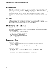
Back Panel Connectors ✏ NOTE The audio line out connector, located on the board. Poor audio quality may occur if passive (non-amplified) speakers are connected to power either headphones or amplified speakers only. A E H C BD F Item A B C D E F G H I J K L M Description PS/2 mouse port PS/2 ...Green Purple Black Black Burgundy Teal Teal Black Black Black Pink Lime green Light blue OM11830 Figure 21. Intel Desktop Boards D850MD and D850MV Product Guide Back Panel Connectors Figure 21 shows the back panel connectors on the back panel, is designed to this output. 66
Back Panel Connectors ✏ NOTE The audio line out connector, located on the board. Poor audio quality may occur if passive (non-amplified) speakers are connected to power either headphones or amplified speakers only. A E H C BD F Item A B C D E F G H I J K L M Description PS/2 mouse port PS/2 ...Green Purple Black Black Burgundy Teal Teal Black Black Black Pink Lime green Light blue OM11830 Figure 21. Intel Desktop Boards D850MD and D850MV Product Guide Back Panel Connectors Figure 21 shows the back panel connectors on the back panel, is designed to this output. 66


