

Product Guide
Page 6
... Audio with Jack Sensing 42 Multi-Channel Analog Audio 42 Multi-Channel Digital Audio 42 Connecting USB 2.0 Headers 43 Connecting the Front Panel Header 43 Connecting Hardware Control and Power Cables 44 Connecting the Chassis Intrusion Cable 45 Connecting Fans ...45 Connecting... Power Cables 45 Setting the BIOS Configuration Jumper Block 46 Clearing Passwords ...47 Replacing the Battery ...48 3 Updating the BIOS Updating the BIOS with the Intel...
... Audio with Jack Sensing 42 Multi-Channel Analog Audio 42 Multi-Channel Digital Audio 42 Connecting USB 2.0 Headers 43 Connecting the Front Panel Header 43 Connecting Hardware Control and Power Cables 44 Connecting the Chassis Intrusion Cable 45 Connecting Fans ...45 Connecting... Power Cables 45 Setting the BIOS Configuration Jumper Block 46 Clearing Passwords ...47 Replacing the Battery ...48 3 Updating the BIOS Updating the BIOS with the Intel...
Product Guide
Page 7
... 5. Installing a Memory Module 34 8. Back Panel Audio Connectors for 6-Channel Audio with Two DIMMs 35 9. Location of Standby Power Indicator 24 3. Dual Configuration Example with Jack Sensing 42 15. Connecting the Serial ATA Cable 39 13. Internal Headers ...40 14. Installing the I/O Shield 30 ...38 12. Dual Configuration Example with Four DIMMs 35 10. Removing the AGP Card 37 11. Location of Hardware Control Headers and Power Connectors 44 vii Contents Video Configuration Submenu 70 USB Configuration Submenu 71 Chipset Configuration Submenu 72 Fan Control Submenu 74...
... 5. Installing a Memory Module 34 8. Back Panel Audio Connectors for 6-Channel Audio with Two DIMMs 35 9. Location of Standby Power Indicator 24 3. Dual Configuration Example with Jack Sensing 42 15. Connecting the Serial ATA Cable 39 13. Internal Headers ...40 14. Installing the I/O Shield 30 ...38 12. Dual Configuration Example with Four DIMMs 35 10. Removing the AGP Card 37 11. Location of Hardware Control Headers and Power Connectors 44 vii Contents Video Configuration Submenu 70 USB Configuration Submenu 71 Chipset Configuration Submenu 72 Fan Control Submenu 74...
Product Guide
Page 8
...24. Removable Devices Submenu 82 36. Exit Menu...84 38. PCI Bus Add-in Card and Peripheral Interface Connectors 88 Tables 1. Front Panel Audio Header Signal Names (J9A2 41 9. Maintenance Menu ...58 15. Hardware Monitoring Submenu 75 29. Power Menu...77 31. Boot Menu ...79 33...87 20. Supported Processors 16 6. Jumper Settings for the BIOS Setup Program Modes (J9J4 46 12. Boot Device Priority Submenu 80 34. Intel Desktop Boards D865GBF/D865GLC Product Guide 16. USB Configuration Submenu 71 26. System Memory Map ...89 39. SATA and PATA Submenus 66 22...
...24. Removable Devices Submenu 82 36. Exit Menu...84 38. PCI Bus Add-in Card and Peripheral Interface Connectors 88 Tables 1. Front Panel Audio Header Signal Names (J9A2 41 9. Maintenance Menu ...58 15. Hardware Monitoring Submenu 75 29. Power Menu...77 31. Boot Menu ...79 33...87 20. Supported Processors 16 6. Jumper Settings for the BIOS Setup Program Modes (J9J4 46 12. Boot Device Priority Submenu 80 34. Intel Desktop Boards D865GBF/D865GLC Product Guide 16. USB Configuration Submenu 71 26. System Memory Map ...89 39. SATA and PATA Submenus 66 22...
Product Guide
Page 12
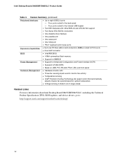
Feature Summary (continued) Peripheral Interfaces • Up to the back panel - Four ports routed to eight USB 2.0 ports - Four ports routed to the internal USB header • Two IDE interfaces with Ultra DMA-33 and ATA-66/100 support • Two Serial ATA (SATA) connectors ...8226; Wake on USB, PCI, RS-232, PS/2, LAN, and front panel Hardware Management • Hardware monitor with: • Three fan sensing inputs used to monitor fan activity • Temperature sensing • Intel® Precision Cooling Technology fan speed control that automatically adjusts chassis fan speeds ...
Feature Summary (continued) Peripheral Interfaces • Up to the back panel - Four ports routed to eight USB 2.0 ports - Four ports routed to the internal USB header • Two IDE interfaces with Ultra DMA-33 and ATA-66/100 support • Two Serial ATA (SATA) connectors ...8226; Wake on USB, PCI, RS-232, PS/2, LAN, and front panel Hardware Management • Hardware monitor with: • Three fan sensing inputs used to monitor fan activity • Temperature sensing • Intel® Precision Cooling Technology fan speed control that automatically adjusts chassis fan speeds ...
Product Guide
Page 15
... drive connector Primary IDE connector Secondary IDE connector Front chassis fan connector (fan speed control) Chassis intrusion header Serial ATA connectors Speaker BIOS configuration jumper Alternate power/sleep LED header Front panel header USB 2.0 header Intel 82801EB (ICH5) USB 2.0 header Battery PCI bus add-in card connectors Related Links: Go to the following links for the latest...
... drive connector Primary IDE connector Secondary IDE connector Front chassis fan connector (fan speed control) Chassis intrusion header Serial ATA connectors Speaker BIOS configuration jumper Alternate power/sleep LED header Front panel header USB 2.0 header Intel 82801EB (ICH5) USB 2.0 header Battery PCI bus add-in card connectors Related Links: Go to the following links for the latest...

Product Guide
Page 20
...rate is communicating with USB 1.1 devices. The computer is selected. four ports routed to the back panel and four routed to operating system and driver initialization. 20 USB 2.0 support requires both an operating...ICH5; Disabling Hi-Speed USB in the BIOS reverts all USB 2.0 ports to the cable. Intel Desktop Boards D865GBF/D865GLC Product Guide RJ-45 LAN Connector LEDs Two LEDs are limited to USB 1.1... transfer rates prior to the internal USB 2.0 headers. Table 6. LAN link is selected. RJ-45 10/100/1000 Gigabit Ethernet LAN Connector ...
...rate is communicating with USB 1.1 devices. The computer is selected. four ports routed to the back panel and four routed to operating system and driver initialization. 20 USB 2.0 support requires both an operating...ICH5; Disabling Hi-Speed USB in the BIOS reverts all USB 2.0 ports to the cable. Intel Desktop Boards D865GBF/D865GLC Product Guide RJ-45 LAN Connector LEDs Two LEDs are limited to USB 1.1... transfer rates prior to the internal USB 2.0 headers. Table 6. LAN link is selected. RJ-45 10/100/1000 Gigabit Ethernet LAN Connector ...
Product Guide
Page 27
... remove a processor and memory • Install and remove an AGP card • Connect the IDE and Serial ATA cables • Connect internal headers • Connecting 6-Channel Flex Audio with the safety practices and regulatory compliance required for using an antistatic wrist strap and a conductive foam pad. ...If such a station is not available, you can continue to operate even though the front panel power button is off. Some circuitry on the board can provide some ESD protection by wearing an antistatic wrist strap and attaching it to...
... remove a processor and memory • Install and remove an AGP card • Connect the IDE and Serial ATA cables • Connect internal headers • Connecting 6-Channel Flex Audio with the safety practices and regulatory compliance required for using an antistatic wrist strap and a conductive foam pad. ...If such a station is not available, you can continue to operate even though the front panel power button is off. Some circuitry on the board can provide some ESD protection by wearing an antistatic wrist strap and attaching it to...
Product Guide
Page 40
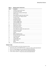
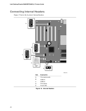
Intel Desktop Boards D865GBF/D865GLC Product Guide Connecting Internal Headers Figure 13 shows the location of internal headers. 1 2 3 4 A5 6 7 9 10 J9A2 1 3 C5 7 1 2 B3 5 4 6 7 8 10 2 4 J9F1 6 8 10 J9H1 1 2 3 4 5 6 D7 8 9 J9J1 E 12 Item A B C D E Description Front panel audio USB 2.0 USB 2.0 Front panel Power LED Figure 13. Internal Headers OM15240 40
Intel Desktop Boards D865GBF/D865GLC Product Guide Connecting Internal Headers Figure 13 shows the location of internal headers. 1 2 3 4 A5 6 7 9 10 J9A2 1 3 C5 7 1 2 B3 5 4 6 7 8 10 2 4 J9F1 6 8 10 J9H1 1 2 3 4 5 6 D7 8 9 J9J1 E 12 Item A B C D E Description Front panel audio USB 2.0 USB 2.0 Front panel Power LED Figure 13. Internal Headers OM15240 40
Product Guide
Page 41
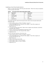
...-FPOUT-L Pin Signal Name 2 AUD-GND 4 AUD-VCC 6 AUD-RET-R 8 KEY 10 AUD-RET-L To install the cable that connects the front panel audio solution to the front panel audio header, follow these steps: 1. Turn off the computer and disconnect the AC power cord. 3. Install a jumper on pins 9-10 (rear L channel). 7. Table 8. Locate...
...-FPOUT-L Pin Signal Name 2 AUD-GND 4 AUD-VCC 6 AUD-RET-R 8 KEY 10 AUD-RET-L To install the cable that connects the front panel audio solution to the front panel audio header, follow these steps: 1. Turn off the computer and disconnect the AC power cord. 3. Install a jumper on pins 9-10 (rear L channel). 7. Table 8. Locate...
Product Guide
Page 42
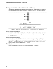
Back Panel Audio Connectors for 6-Channel Audio with Jack Sensing After installing the SoundMAX 4 XL audio driver from the stereo input to RCA connection. Connect the stereo input side of the ATAPI-style audio headers, go to page 87 in Chapter 5. 42 and 6-channel audio configurations. Related Link...Rear left/right out or Line In Front left/right out or S/PDIF line out Center-LFE (Subwoofer) or Mic In Figure 14. Intel Desktop Boards D865GBF/D865GLC Product Guide Setting up the Flexible 6-Channel Audio with Jack Sensing Multi-Channel Analog Audio Connect two speakers to the ...
Back Panel Audio Connectors for 6-Channel Audio with Jack Sensing After installing the SoundMAX 4 XL audio driver from the stereo input to RCA connection. Connect the stereo input side of the ATAPI-style audio headers, go to page 87 in Chapter 5. 42 and 6-channel audio configurations. Related Link...Rear left/right out or Line In Front left/right out or S/PDIF line out Center-LFE (Subwoofer) or Mic In Figure 14. Intel Desktop Boards D865GBF/D865GLC Product Guide Setting up the Flexible 6-Channel Audio with Jack Sensing Multi-Channel Analog Audio Connect two speakers to the ...
Product Guide
Page 43
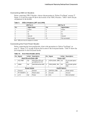
... shows the pin assignments for the front panel header. Figure 13-C on page 40 shows the location of the USB 2.0 headers. USB Port B Signal Name Power DD+ Ground Not connected Connecting the Front Panel Header Before connecting the front panel header, observe the precautions in "Before You ...Begin" on page 40 shows the location of the front panel header. Figure 13-A and -B on page 27. Table 10 shows the pin assignments for the headers. Table 9. Front Panel Header (J9J1) ...
... shows the pin assignments for the front panel header. Figure 13-C on page 40 shows the location of the USB 2.0 headers. USB Port B Signal Name Power DD+ Ground Not connected Connecting the Front Panel Header Before connecting the front panel header, observe the precautions in "Before You ...Begin" on page 40 shows the location of the front panel header. Figure 13-A and -B on page 27. Table 10 shows the pin assignments for the headers. Table 9. Front Panel Header (J9J1) ...


