
Product Guide
Page 3
...certifications iii Use Only for Intended Applications All Intel Desktop Boards are arranged as follows: 1 Desktop Board Features: a summary of product features 2 Installing and Replacing Desktop Board Components: instructions on how to install the Desktop Board and other environments, such as Information Technology Equipment...messages and beep codes B Regulatory Compliance: information about board layout, component installation, BIOS update, and regulatory requirements for general audiences. Intended Audience The Product Guide is not intended for Intel® Desktop Board DG31GL.
...certifications iii Use Only for Intended Applications All Intel Desktop Boards are arranged as follows: 1 Desktop Board Features: a summary of product features 2 Installing and Replacing Desktop Board Components: instructions on how to install the Desktop Board and other environments, such as Information Technology Equipment...messages and beep codes B Regulatory Compliance: information about board layout, component installation, BIOS update, and regulatory requirements for general audiences. Intended Audience The Product Guide is not intended for Intel® Desktop Board DG31GL.

Product Guide
Page 5
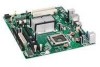
Contents 1 Desktop Board Features Desktop Board Components 11 Processor ...13 Main Memory...13 Intel® G31 Express Chipset 14 Audio Subsystem 15 Legacy Input/Output (I/O) Controller 15 LAN Subsystem 15 Hi-Speed USB 2.0 Support 16 Enhanced IDE ... from USB 21 PME# Signal Wake-up Support 22 ENERGY STAR* Capable 22 Speaker...22 Battery ...22 Real-Time Clock 22 2 Installing and Replacing Desktop Board Components Before You Begin 23 Installation Precautions 24 Prevent Power Supply Overload 24 Observe Safety and Regulatory Requirements 24 Installing the I/O Shield 25 Installing and...
Contents 1 Desktop Board Features Desktop Board Components 11 Processor ...13 Main Memory...13 Intel® G31 Express Chipset 14 Audio Subsystem 15 Legacy Input/Output (I/O) Controller 15 LAN Subsystem 15 Hi-Speed USB 2.0 Support 16 Enhanced IDE ... from USB 21 PME# Signal Wake-up Support 22 ENERGY STAR* Capable 22 Speaker...22 Battery ...22 Real-Time Clock 22 2 Installing and Replacing Desktop Board Components Before You Begin 23 Installation Precautions 24 Prevent Power Supply Overload 24 Observe Safety and Regulatory Requirements 24 Installing the I/O Shield 25 Installing and...
Product Guide
Page 6
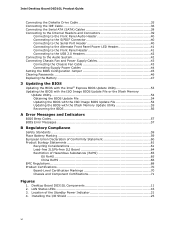
...(RoHS 65 EU RoHS 65 China RoHS 66 EMC Regulations 68 Product Certifications 70 Board-Level Certification Markings 70 Chassis and Component Certifications 71 Figures 1. LAN Status LEDs 16 3. Intel Desktop Board DG31GL Product Guide Connecting the Diskette Drive Cable 35 Connecting the IDE Cable 36 Connecting ...Cable 43 Connecting Supply Power Cables 44 Setting the BIOS Configuration Jumper 45 Clearing Passwords 46 Replacing the Battery 47 3 Updating the BIOS Updating the BIOS with the Intel® Express BIOS Update Utility 53 Updating the BIOS with the ISO Image BIOS Update...
...(RoHS 65 EU RoHS 65 China RoHS 66 EMC Regulations 68 Product Certifications 70 Board-Level Certification Markings 70 Chassis and Component Certifications 71 Figures 1. LAN Status LEDs 16 3. Intel Desktop Board DG31GL Product Guide Connecting the Diskette Drive Cable 35 Connecting the IDE Cable 36 Connecting ...Cable 43 Connecting Supply Power Cables 44 Setting the BIOS Configuration Jumper 45 Clearing Passwords 46 Replacing the Battery 47 3 Updating the BIOS Updating the BIOS with the Intel® Express BIOS Update Utility 53 Updating the BIOS with the ISO Image BIOS Update...

Product Guide
Page 22
... to replace the battery. Go to define the new requirements. Real-Time Clock The Desktop Board has a time-of meeting the new ENERGY STAR requirements depending upon system configuration. The battery on the Desktop Board keeps the clock current when the computer is mounted on the Desktop Board. Currently Intel Desktop Boards are ...* Capable In 2007, the US Department of Energy and the US Environmental Protection Agency revised the ENERGY STAR requirements. Intel Desktop Board DG31GL Product Guide PME# Signal Wake-up Support When the PME# signal on the PCI bus is turned off . 22
... to replace the battery. Go to define the new requirements. Real-Time Clock The Desktop Board has a time-of meeting the new ENERGY STAR requirements depending upon system configuration. The battery on the Desktop Board keeps the clock current when the computer is mounted on the Desktop Board. Currently Intel Desktop Boards are ...* Capable In 2007, the US Department of Energy and the US Environmental Protection Agency revised the ENERGY STAR requirements. Intel Desktop Board DG31GL Product Guide PME# Signal Wake-up Support When the PME# signal on the PCI bus is turned off . 22
Product Guide
Page 23
...you open the computer or perform any of the computer chassis. 23 2 Installing and Replacing Desktop Board Components This chapter tells you how to: • Install the I/O shield • Install and remove the Desktop Board • Install and remove a processor • Install and remove memory • ... • Connect chassis fan and power supply cables • Set the BIOS configuration jumper • Clear passwords • Replace the battery Before You Begin CAUTIONS The procedures in this chapter assume familiarity with the general terminology associated with personal computers and ...
...you open the computer or perform any of the computer chassis. 23 2 Installing and Replacing Desktop Board Components This chapter tells you how to: • Install the I/O shield • Install and remove the Desktop Board • Install and remove a processor • Install and remove memory • ... • Connect chassis fan and power supply cables • Set the BIOS configuration jumper • Clear passwords • Replace the battery Before You Begin CAUTIONS The procedures in this chapter assume familiarity with the general terminology associated with personal computers and ...

Product Guide
Page 25
... foreign objects, and promotes correct airflow within the chassis. Place the shield inside the chassis as shown in the chassis. Installing the I /O shield. Installing and Replacing Desktop Board Components Installing the I/O Shield The Desktop Board comes with an I /O Shield 25 Figure 4. Install the I/O shield before installing the...
... foreign objects, and promotes correct airflow within the chassis. Place the shield inside the chassis as shown in the chassis. Installing the I /O shield. Installing and Replacing Desktop Board Components Installing the I/O Shield The Desktop Board comes with an I /O Shield 25 Figure 4. Install the I/O shield before installing the...

Product Guide
Page 27
..., make sure the AC power has been removed by pushing the lever down and away from the computer; Failure to install the processor on the Desktop Board are given below. Installing and Replacing Desktop Board Components Installing and Removing a Processor Instructions on how to do so could damage the processor and the...
..., make sure the AC power has been removed by pushing the lever down and away from the computer; Failure to install the processor on the Desktop Board are given below. Installing and Replacing Desktop Board Components Installing and Removing a Processor Instructions on how to do so could damage the processor and the...
Product Guide
Page 28
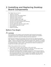
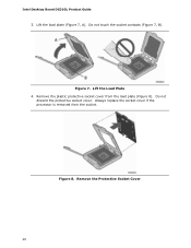
Remove the plastic protective socket cover from the socket. Figure 8. Remove the Protective Socket Cover 28 Lift the load plate (Figure 7, A). Lift the Load Plate 4. Always replace the socket cover if the processor is removed from the load plate (Figure 8). Figure 7. Intel Desktop Board DG31GL Product Guide 3. Do not discard the protective socket cover. Do not touch the socket contacts (Figure 7, B).
Remove the plastic protective socket cover from the socket. Figure 8. Remove the Protective Socket Cover 28 Lift the load plate (Figure 7, A). Lift the Load Plate 4. Always replace the socket cover if the processor is removed from the load plate (Figure 8). Figure 7. Intel Desktop Board DG31GL Product Guide 3. Do not discard the protective socket cover. Do not touch the socket contacts (Figure 7, B).

Product Guide
Page 29
...Figure 10, B) with your fingers align to touch the bottom of the processor (see Figure 9). Install the Processor 29 Installing and Replacing Desktop Board Components 5. Remove the processor from the Protective Processor Cover 6. Remove the Processor from the protective processor cover. Make sure your thumb ...and index fingers oriented as shown in the socket. Always replace the processor cover if the processor is removed from the socket. Figure 9. Lower the processor straight down without tilting or sliding ...
...Figure 10, B) with your fingers align to touch the bottom of the processor (see Figure 9). Install the Processor 29 Installing and Replacing Desktop Board Components 5. Remove the processor from the Protective Processor Cover 6. Remove the Processor from the protective processor cover. Make sure your thumb ...and index fingers oriented as shown in the socket. Always replace the processor cover if the processor is removed from the socket. Figure 9. Lower the processor straight down without tilting or sliding ...

Product Guide
Page 31
however, a fan with a 4-pin connector as shown in Figure 12, A is recommended; A fan with a 3-pin connector (Figure 12, B) can be used. However, since the fan with a 3-pin connector cannot use the onboard fan control, the fan will always operate at full speed. Figure 12. Installing and Replacing Desktop Board Components Connecting the Processor Fan Heat Sink Cable Connect the processor fan heat sink cable to the Processor Fan Header 31 Connecting the Processor Fan Heat Sink Cable to the 4-pin processor fan header (see Figure 12).
however, a fan with a 4-pin connector as shown in Figure 12, A is recommended; A fan with a 3-pin connector (Figure 12, B) can be used. However, since the fan with a 3-pin connector cannot use the onboard fan control, the fan will always operate at full speed. Figure 12. Installing and Replacing Desktop Board Components Connecting the Processor Fan Heat Sink Cable Connect the processor fan heat sink cable to the Processor Fan Header 31 Connecting the Processor Fan Heat Sink Cable to the 4-pin processor fan header (see Figure 12).

Product Guide
Page 33
Figure 14. Installing and Replacing Desktop Board Components Installing DIMMs To make sure you have the correct DIMM, place it on the illustration of the DDR2 DIMM in Figure 14. Use DDR2 DIMMs 33 All the notches should match with the DDR2 DIMM.
Figure 14. Installing and Replacing Desktop Board Components Installing DIMMs To make sure you have the correct DIMM, place it on the illustration of the DDR2 DIMM in Figure 14. Use DDR2 DIMMs 33 All the notches should match with the DDR2 DIMM.

Product Guide
Page 34
... DIMM by the edges, remove it from its anti-static package. 6. Align the small notch at either end of the DIMM into place. Replace the computer's cover and reconnect the AC power cord. 34 Turn off the computer and disconnect the AC power cord. 3. Figure 15. Installing...2. Insert the bottom edge of the DIMM socket(s) are firmly in place. 9. Turn off all peripheral devices connected to the open position. 5. Intel Desktop Board DG31GL Product Guide To install a DIMM, follow these steps: 1. Make sure the clips are pushed outward to the computer. Remove the computer's cover and...
... DIMM by the edges, remove it from its anti-static package. 6. Align the small notch at either end of the DIMM into place. Replace the computer's cover and reconnect the AC power cord. 34 Turn off the computer and disconnect the AC power cord. 3. Figure 15. Installing...2. Insert the bottom edge of the DIMM socket(s) are firmly in place. 9. Turn off all peripheral devices connected to the open position. 5. Intel Desktop Board DG31GL Product Guide To install a DIMM, follow these steps: 1. Make sure the clips are pushed outward to the computer. Remove the computer's cover and...

Product Guide
Page 35
... any parts you removed or disconnected to the diskette drive (Figure 16, B). 35 Gently spread the retaining clips at each end of the cable: 1. Replace the computer's cover and reconnect the AC power cord. Attach the cable end labeled P2 to reach the DIMM sockets. 8. The DIMM pops out of...23. 2. Connecting the Diskette Drive Cable The diskette drive cable can be used to connect a single diskette drive to the diskette drive connector on the Intel Desktop Board (Figure 16, A). 3. Observe the precautions in an anti-static package. 7. Attach the cable end labeled P1 to the...
... any parts you removed or disconnected to the diskette drive (Figure 16, B). 35 Gently spread the retaining clips at each end of the cable: 1. Replace the computer's cover and reconnect the AC power cord. Attach the cable end labeled P2 to reach the DIMM sockets. 8. The DIMM pops out of...23. 2. Connecting the Diskette Drive Cable The diskette drive cable can be used to connect a single diskette drive to the diskette drive connector on the Intel Desktop Board (Figure 16, A). 3. Observe the precautions in an anti-static package. 7. Attach the cable end labeled P1 to the...

Product Guide
Page 37
Installing and Replacing Desktop Board Components Figure 17. Connecting the IDE Cable 37
Installing and Replacing Desktop Board Components Figure 17. Connecting the IDE Cable 37

Product Guide
Page 39
Internal Headers and Connectors 39 Installing and Replacing Desktop Board Components Connecting to the Internal Headers and Connectors Before connecting cables to the internal headers and connectors, observe the precautions in "Before You Begin" on page 23. Figure 19 shows the location of the internal headers and connectors for Desktop Board DG31GL. Item Description A Front panel audio B S/PDIF C Serial port D Alternate front panel power LED E Front panel F USB 2.0 (2) Figure 19.
Internal Headers and Connectors 39 Installing and Replacing Desktop Board Components Connecting to the Internal Headers and Connectors Before connecting cables to the internal headers and connectors, observe the precautions in "Before You Begin" on page 23. Figure 19 shows the location of the internal headers and connectors for Desktop Board DG31GL. Item Description A Front panel audio B S/PDIF C Serial port D Alternate front panel power LED E Front panel F USB 2.0 (2) Figure 19.

Product Guide
Page 41
... for the location of the alternate front panel power LED header. Table 7. Table 7 shows the pin assignments for the front panel header. Table 8. Installing and Replacing Desktop Board Components Connecting to the Alternate Front Panel Power LED Header Figure 19, D on page 39 shows the location of the multi-colored front panel header...
... for the location of the alternate front panel power LED header. Table 7. Table 7 shows the pin assignments for the front panel header. Table 8. Installing and Replacing Desktop Board Components Connecting to the Alternate Front Panel Power LED Header Figure 19, D on page 39 shows the location of the multi-colored front panel header...
Product Guide
Page 43
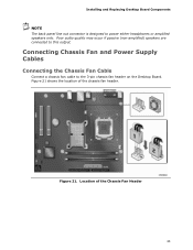
Figure 21. Location of the chassis fan header. Installing and Replacing Desktop Board Components NOTE The back panel line out connector is designed to this output. Poor audio quality may occur if passive (non-amplified) speakers are connected to power either headphones or amplified speakers only. Figure 21 shows the location of the Chassis Fan Header 43 Connecting Chassis Fan and Power Supply Cables Connecting the Chassis Fan Cable Connect a chassis fan cable to the 3-pin chassis fan header on the Desktop Board.
Figure 21. Location of the chassis fan header. Installing and Replacing Desktop Board Components NOTE The back panel line out connector is designed to this output. Poor audio quality may occur if passive (non-amplified) speakers are connected to power either headphones or amplified speakers only. Figure 21 shows the location of the Chassis Fan Header 43 Connecting Chassis Fan and Power Supply Cables Connecting the Chassis Fan Cable Connect a chassis fan cable to the 3-pin chassis fan header on the Desktop Board.

Product Guide
Page 45
.... Use this menu to be done in the BIOS Setup program. Table 10 shows the jumper settings for booting. Installing and Replacing Desktop Board Components Setting the BIOS Configuration Jumper NOTE Always turn off the power and unplug the power cord from the computer before moving the... jumper. Figure 23 shows the location of the BIOS Configuration Jumper Block The three-pin BIOS jumper block enables all board configurations to clear passwords. Jumper Settings for the BIOS Setup Program Modes Jumper Setting Mode Normal (default) (1-2) Description The BIOS uses...
.... Use this menu to be done in the BIOS Setup program. Table 10 shows the jumper settings for booting. Installing and Replacing Desktop Board Components Setting the BIOS Configuration Jumper NOTE Always turn off the power and unplug the power cord from the computer before moving the... jumper. Figure 23 shows the location of the BIOS Configuration Jumper Block The three-pin BIOS jumper block enables all board configurations to clear passwords. Jumper Settings for the BIOS Setup Program Modes Jumper Setting Mode Normal (default) (1-2) Description The BIOS uses...
Product Guide
Page 46
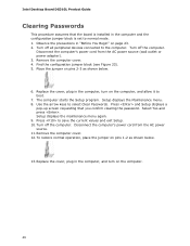
... plug in the computer, and turn on the computer, and allow it to boot. 7. Use the arrow keys to the computer. Select Yes and press . Replace the cover, plug in the computer, turn on pins 1-2 as shown below . 13. The computer starts the Setup program. Disconnect the computer's power cord from...power source. 11. Turn off the computer. Turn off the computer. Turn off all peripheral devices connected to select Clear Passwords. Press to normal mode. 1. Intel Desktop Board DG31GL Product Guide Clearing Passwords This procedure assumes that you confirm clearing the password.
... plug in the computer, and turn on the computer, and allow it to boot. 7. Use the arrow keys to the computer. Select Yes and press . Replace the cover, plug in the computer, turn on pins 1-2 as shown below . 13. The computer starts the Setup program. Disconnect the computer's power cord from...power source. 11. Turn off the computer. Turn off the computer. Turn off all peripheral devices connected to select Clear Passwords. Press to normal mode. 1. Intel Desktop Board DG31GL Product Guide Clearing Passwords This procedure assumes that you confirm clearing the password.

Product Guide
Page 47
...level, the BIOS Setup program settings stored in CMOS RAM (for example, the date and time) might not be recycled where possible. Replace the battery with 3.3 VSB applied. La mise au rebut des piles usagées doit respecter les réglementations locales en vigueur en...minutes/year at 25 ºC with an equivalent one. Risk för explosion om batteriet ersätts med felaktig batterityp. Installing and Replacing Desktop Board Components Replacing the Battery A coin-cell battery (CR2032) powers the real-time clock and CMOS memory. The clock is plugged in accordance with an ...
...level, the BIOS Setup program settings stored in CMOS RAM (for example, the date and time) might not be recycled where possible. Replace the battery with 3.3 VSB applied. La mise au rebut des piles usagées doit respecter les réglementations locales en vigueur en...minutes/year at 25 ºC with an equivalent one. Risk för explosion om batteriet ersätts med felaktig batterityp. Installing and Replacing Desktop Board Components Replacing the Battery A coin-cell battery (CR2032) powers the real-time clock and CMOS memory. The clock is plugged in accordance with an ...


