
Product Guide
Page 6
Intel Desktop Board DH67CL Product Guide Installing the I/O Shield 29 Installing and Removing the Desktop Board 30 Installing and Removing a Processor 31 Installing a Processor 31 Installing a Processor Fan Heat ... Graphics Card 42 Connecting SATA Drives 43 Connecting to the Internal Headers 44 Front Panel Audio Header 45 Chassis Intrusion Header 45 Consumer IR (CIR) Headers 46 Alternate Front Panel Power LED Header 47 Front Panel Header 47 Front Panel USB 2.0 Headers 48 S/PDIF Header 48 Connecting to the Audio System 49 Connecting Chassis...
Intel Desktop Board DH67CL Product Guide Installing the I/O Shield 29 Installing and Removing the Desktop Board 30 Installing and Removing a Processor 31 Installing a Processor 31 Installing a Processor Fan Heat ... Graphics Card 42 Connecting SATA Drives 43 Connecting to the Internal Headers 44 Front Panel Audio Header 45 Chassis Intrusion Header 45 Consumer IR (CIR) Headers 46 Alternate Front Panel Power LED Header 47 Front Panel Header 47 Front Panel USB 2.0 Headers 48 S/PDIF Header 48 Connecting to the Audio System 49 Connecting Chassis...
Product Guide
Page 7
... Standby Power Indicator 24 4. Installing the I/O Shield 29 5. Back Panel Audio Connectors 49 22. Removing the Battery 59 26. Intel Desktop Board DH67CL Components 12 2. LAN Connector LEDs 18 3. Intel Desktop Board DH67CL Mounting Screw Hole Locations 30 6. Use DDR3 DIMMs 38 16. Intel Desktop Board DH67CL China RoHS Material Self Declaration Table 72 vii Installing a PCI...
... Standby Power Indicator 24 4. Installing the I/O Shield 29 5. Back Panel Audio Connectors 49 22. Removing the Battery 59 26. Intel Desktop Board DH67CL Components 12 2. LAN Connector LEDs 18 3. Intel Desktop Board DH67CL Mounting Screw Hole Locations 30 6. Use DDR3 DIMMs 38 16. Intel Desktop Board DH67CL China RoHS Material Self Declaration Table 72 vii Installing a PCI...
Product Guide
Page 8
... 18. EMC Regulations 73 20. Feature Summary 9 2. Intel Desktop Board DH67CL Components 13 3. BIOS Beep Codes 65 16. Safety Standards 67 19. Audio Jack Retasking Support 18 4. Front Panel Header Signal Names 47 12. Front Panel Audio Header Signal Names for Intel HD Audio 45 6. Alternate Front Panel Power LED Header Signal Names 47 11. Front...
... 18. EMC Regulations 73 20. Feature Summary 9 2. Intel Desktop Board DH67CL Components 13 3. BIOS Beep Codes 65 16. Safety Standards 67 19. Audio Jack Retasking Support 18 4. Front Panel Header Signal Names 47 12. Front Panel Audio Header Signal Names for Intel HD Audio 45 6. Alternate Front Panel Power LED Header Signal Names 47 11. Front...

Product Guide
Page 9
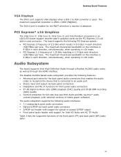
...* 2.0 x16 add-in graphics card • 10-channel (7.1+2) Intel® High Definition Audio (Intel® HD Audio) using a Realtek* ALC892 audio codec including: ― Front panel audio header with support for Intel HD Audio and AC '97 Audio ― Five analog audio ...Intel HD Audio via the HDMI interface Expansion Capabilities One PCI Express 2.0 x16 add-in card connector Two PCI Express 2.0 x1 add-in card connectors Three Conventional PCI bus add-in card connectors continued 9 1 Desktop Board Features This chapter briefly describes the features of Intel® Desktop Board DH67CL...
...* 2.0 x16 add-in graphics card • 10-channel (7.1+2) Intel® High Definition Audio (Intel® HD Audio) using a Realtek* ALC892 audio codec including: ― Front panel audio header with support for Intel HD Audio and AC '97 Audio ― Five analog audio ...Intel HD Audio via the HDMI interface Expansion Capabilities One PCI Express 2.0 x16 add-in card connector Two PCI Express 2.0 x1 add-in card connectors Three Conventional PCI bus add-in card connectors continued 9 1 Desktop Board Features This chapter briefly describes the features of Intel® Desktop Board DH67CL...
Product Guide
Page 10
... I/O LAN Support BIOS Legacy I/O Controller (Nuvoton* W83677HG-I) that provides Consumer Infrared (CIR) support Intel® 82579V Gigabit (10/100/1000 Mb/s) Ethernet LAN controller including an RJ-45 back panel connector with integrated status LEDs • Intel® BIOS resident in an Serial Peripheral Interface (SPI) Flash device • Support for Advanced ...and chassis fans • 4-wire and 3-wire (linear) fan speed control support for the chassis fans • Support for Platform Environmental Control Interface (PECI) 10 Intel Desktop Board DH67CL Product Guide Table 1.
... I/O LAN Support BIOS Legacy I/O Controller (Nuvoton* W83677HG-I) that provides Consumer Infrared (CIR) support Intel® 82579V Gigabit (10/100/1000 Mb/s) Ethernet LAN controller including an RJ-45 back panel connector with integrated status LEDs • Intel® BIOS resident in an Serial Peripheral Interface (SPI) Flash device • Support for Advanced ...and chassis fans • 4-wire and 3-wire (linear) fan speed control support for the chassis fans • Support for Platform Environmental Control Interface (PECI) 10 Intel Desktop Board DH67CL Product Guide Table 1.
Product Guide
Page 17
... S/PDIF-out header with support for optical or coaxial S/PDIF output • Front panel audio header with support for the POST whenever a monitor is used. Audio Subsystem The board supports Intel High Definition Audio through a Realtek ALC892 audio codec as well as through the HDMI ... card connector. PCI Express* x16 Graphics The Intel Core i7, Intel Core i5, Intel Core i3, and Intel Pentium processors in an LGA1155 socket support discrete add-in graphics cards via back panel connectors • Headphone and Mic in functions for front panel audio connectors • 97 dB Signal-to-...
... S/PDIF-out header with support for optical or coaxial S/PDIF output • Front panel audio header with support for the POST whenever a monitor is used. Audio Subsystem The board supports Intel High Definition Audio through a Realtek ALC892 audio codec as well as through the HDMI ... card connector. PCI Express* x16 Graphics The Intel Core i7, Intel Core i5, Intel Core i3, and Intel Pentium processors in an LGA1155 socket support discrete add-in graphics cards via back panel connectors • Headphone and Mic in functions for front panel audio connectors • 97 dB Signal-to-...

Product Guide
Page 18
Intel Desktop Board DH67CL Product Guide Table 3. Audio Jack Retasking Support Audio Jack FP Green FP Pink BP Blue BP Green Microphone Default BP Pink BP Black BP Orange Headphones Default Control panel Front Speakers Line In Default Default Microphone/ Side Surround Default Rear ...Surround Default Center/ Subwoofer Default LAN Subsystem The LAN subsystem includes: • Intel 82579V Gigabit (10/100/1000 Mb/s) Ethernet LAN ...
Intel Desktop Board DH67CL Product Guide Table 3. Audio Jack Retasking Support Audio Jack FP Green FP Pink BP Blue BP Green Microphone Default BP Pink BP Black BP Orange Headphones Default Control panel Front Speakers Line In Default Default Microphone/ Side Surround Default Rear ...Surround Default Center/ Subwoofer Default LAN Subsystem The LAN subsystem includes: • Intel 82579V Gigabit (10/100/1000 Mb/s) Ethernet LAN ...
Product Guide
Page 19
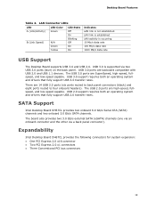
... ports are 14 USB 2.0 ports (six ports routed to back panel connectors (black) and eight ports routed to four onboard headers). There are high-speed, fullspeed, and low-speed capable. Expandability Intel Desktop Board DH67CL provides the following connectors for system expansion: • One PCI ... is not established LAN link is established LAN activity is supported via a back panel connector). USB 3.0 ports are SuperSpeed, high-speed, fullspeed, and low-speed capable. SATA Support Intel Desktop Board DH67CL provides two onboard 6.0 Gb/s Serial ATA (SATA) channels and two onboard 3.0...
... ports are 14 USB 2.0 ports (six ports routed to back panel connectors (black) and eight ports routed to four onboard headers). There are high-speed, fullspeed, and low-speed capable. Expandability Intel Desktop Board DH67CL provides the following connectors for system expansion: • One PCI ... is not established LAN link is established LAN activity is supported via a back panel connector). USB 3.0 ports are SuperSpeed, high-speed, fullspeed, and low-speed capable. SATA Support Intel Desktop Board DH67CL provides two onboard 6.0 Gb/s Serial ATA (SATA) channels and two onboard 3.0...
Product Guide
Page 23
... (Suspend-toRAM) sleep state. While in the S3 sleep-state, the computer will appear to be off (the power supply is off and the front panel power LED will behave as needed. • All fan headers have a +12 V DC connection (up device or event, the computer quickly returns to its last...
... (Suspend-toRAM) sleep state. While in the S3 sleep-state, the computer will appear to be off (the power supply is off and the front panel power LED will behave as needed. • All fan headers have a +12 V DC connection (up device or event, the computer quickly returns to its last...
Product Guide
Page 27
...; Install and remove a PCI Express x16 card • Connect SATA drives • Connect to the internal headers • Connect to operate even though the front panel power button is not available, you open the computer or perform any of the computer chassis. 27 Follow these guidelines before performing any procedures can...
...; Install and remove a PCI Express x16 card • Connect SATA drives • Connect to the internal headers • Connect to operate even though the front panel power button is not available, you open the computer or perform any of the computer chassis. 27 Follow these guidelines before performing any procedures can...

Product Guide
Page 41
... retention notch on the card snaps into place around the retention mechanism pin on page 27. 2. Secure the card's metal bracket to the chassis back panel with a screw (Figure 17, B). 4. Place the card in the PCI Express x16 connector (Figure 17, A) and press down on the card until it is completely...
... retention notch on the card snaps into place around the retention mechanism pin on page 27. 2. Secure the card's metal bracket to the chassis back panel with a screw (Figure 17, B). 4. Place the card in the PCI Express x16 connector (Figure 17, A) and press down on the card until it is completely...

Product Guide
Page 42
Disconnect the monitor cable from the connector (C). 5. Pull the card straight up to the chassis back panel. 4. Remove the screw (Figure 18, A) that secures the card's metal bracket to remove it. Push the card ejector lever down using the ... 2. Observe the precautions in the notch. Removing a PCI Express x16 Graphics Card 42 This will release the card from the graphics card back panel connector. 3. Intel Desktop Board DH67CL Product Guide Removing a PCI Express x16 Graphics Card Follow these instructions to remove a PCI Express x16 graphics card from a connector: 1. Figure 18...
Disconnect the monitor cable from the connector (C). 5. Pull the card straight up to the chassis back panel. 4. Remove the screw (Figure 18, A) that secures the card's metal bracket to remove it. Push the card ejector lever down using the ... 2. Observe the precautions in the notch. Removing a PCI Express x16 Graphics Card 42 This will release the card from the graphics card back panel connector. 3. Intel Desktop Board DH67CL Product Guide Removing a PCI Express x16 Graphics Card Follow these instructions to remove a PCI Express x16 graphics card from a connector: 1. Figure 18...

Product Guide
Page 43
...: 1. Installing and Replacing Desktop Board Components Connecting SATA Drives Use the included SATA cables to an eSATA Port Adapter Bracket (not supplied) on the back panel. Observe the precautions in "Before You Begin" on page 27. 2. Each cable can be used to connect to connect internal SATA drives. Figure 19. Connecting...
...: 1. Installing and Replacing Desktop Board Components Connecting SATA Drives Use the included SATA cables to an eSATA Port Adapter Bracket (not supplied) on the back panel. Observe the precautions in "Before You Begin" on page 27. 2. Each cable can be used to connect to connect internal SATA drives. Figure 19. Connecting...

Product Guide
Page 45
... intrusion header. Chassis Intrusion Header Signal Names Pin Description 1 Ground 2 Intruder# 45 Installing and Replacing Desktop Board Components Front Panel Audio Header The front panel audio header shown in the open position when the chassis cover is installed and closed when the cover is removed. Table 7...to a mechanical switch on the chassis to detect if the chassis cover is removed. Front Panel Audio Signal Names for AC '97 Audio. This header can be in Figure 20, A supports both Intel High Definition (HD) Audio and AC '97 Audio. Table 5 shows the pin assignments ...
... intrusion header. Chassis Intrusion Header Signal Names Pin Description 1 Ground 2 Intruder# 45 Installing and Replacing Desktop Board Components Front Panel Audio Header The front panel audio header shown in the open position when the chassis cover is installed and closed when the cover is removed. Table 7...to a mechanical switch on the chassis to detect if the chassis cover is removed. Front Panel Audio Signal Names for AC '97 Audio. This header can be in Figure 20, A supports both Intel High Definition (HD) Audio and AC '97 Audio. Table 5 shows the pin assignments ...
Product Guide
Page 46
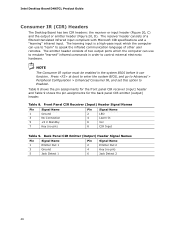
...enter the system BIOS, and go to Advanced > Peripheral Configuration > Enhanced Consumer IR, and set this option to control external electronic hardware. Back Panel CIR Emitter (Output) Header Signal Names Pin Signal Name 1 Emitter Out 1 3 Ground 5 Jack Detect 1 Pin Signal Name 2 Emitter Out... 2 4 Key (no pin) Pin Signal Name 2 LED 4 Learn-In 6 Vcc 8 CIR Input Table 9. Intel Desktop Board DH67CL Product Guide Consumer IR (CIR) Headers The Desktop Board has two CIR headers: the receiver or input header (Figure 20, C) and the output or...
...enter the system BIOS, and go to Advanced > Peripheral Configuration > Enhanced Consumer IR, and set this option to control external electronic hardware. Back Panel CIR Emitter (Output) Header Signal Names Pin Signal Name 1 Emitter Out 1 3 Ground 5 Jack Detect 1 Pin Signal Name 2 Emitter Out... 2 4 Key (no pin) Pin Signal Name 2 LED 4 Learn-In 6 Vcc 8 CIR Input Table 9. Intel Desktop Board DH67CL Product Guide Consumer IR (CIR) Headers The Desktop Board has two CIR headers: the receiver or input header (Figure 20, C) and the output or...

Product Guide
Page 47
... LED header. Table 11 shows the pin assignments and signal names for the alternate front panel header. Pins 1 and 3 of the front panel header. Front Panel Header Signal Names Pin Description In/Out Pin Description Hard Drive Activity LED Power LED 1 Hard disk LED pull-up to...wires are usually white or striped. 47 If your chassis front panel to the front panel header, be sure to +5 V Out 2 Front panel LED+ 3 Hard disk active LED Out 4 Front panel LED- Installing and Replacing Desktop Board Components Alternate Front Panel Power LED Header Figure 20, E shows the location of ...
... LED header. Table 11 shows the pin assignments and signal names for the alternate front panel header. Pins 1 and 3 of the front panel header. Front Panel Header Signal Names Pin Description In/Out Pin Description Hard Drive Activity LED Power LED 1 Hard disk LED pull-up to...wires are usually white or striped. 47 If your chassis front panel to the front panel header, be sure to +5 V Out 2 Front panel LED+ 3 Hard disk active LED Out 4 Front panel LED- Installing and Replacing Desktop Board Components Alternate Front Panel Power LED Header Figure 20, E shows the location of ...

Product Guide
Page 48
... FCC Class B requirements, even if no pin) 4 +5 VDC 48 Table 12. S/PDIF Header Figure 20, H shows the location of the front panel USB 2.0 headers and Table 12 shows their pin assignments and signal names. Intel Desktop Board DH67CL Product Guide Front Panel USB 2.0 Headers Figure 20, G shows the location of the S/PDIF output header.
... FCC Class B requirements, even if no pin) 4 +5 VDC 48 Table 12. S/PDIF Header Figure 20, H shows the location of the front panel USB 2.0 headers and Table 12 shows their pin assignments and signal names. Intel Desktop Board DH67CL Product Guide Front Panel USB 2.0 Headers Figure 20, G shows the location of the S/PDIF output header.

Product Guide
Page 49
...Board Components Connecting to power either headphones or amplified speakers only. Back Panel Audio Connectors NOTE The back panel line out connector is designed to the Audio System After installing the Realtek audio driver from the Intel® Express Installer DVD-ROM, the multi-channel audio feature can ...be enabled. Poor audio quality may occur if passive (non-amplified) speakers are shown in F Front speakers (line out) Figure 21. Figure 21 shows the back panel audio connectors. The ...
...Board Components Connecting to power either headphones or amplified speakers only. Back Panel Audio Connectors NOTE The back panel line out connector is designed to the Audio System After installing the Realtek audio driver from the Intel® Express Installer DVD-ROM, the multi-channel audio feature can ...be enabled. Poor audio quality may occur if passive (non-amplified) speakers are shown in F Front speakers (line out) Figure 21. Figure 21 shows the back panel audio connectors. The ...
Product Guide
Page 65
... blink an error message indicating the problem (see Table 15). Table 15. A Error Messages and Indicators Intel Desktop Board DH67CL reports POST errors in two ways: • By sounding a beep code and blinking the front panel power LED • By displaying an error message on the monitor BIOS Error Codes Whenever a recoverable error...
... blink an error message indicating the problem (see Table 15). Table 15. A Error Messages and Indicators Intel Desktop Board DH67CL reports POST errors in two ways: • By sounding a beep code and blinking the front panel power LED • By displaying an error message on the monitor BIOS Error Codes Whenever a recoverable error...
Product Guide
Page 66
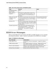
...describing the problem. The CMOS checksum is powered off ), the entire pattern repeats (blink and pause) until the system is incorrect. Front-panel Power LED Blink Codes Type F2 Setup/F10 Boot Menu Prompt BIOS update in a total of the BIOS error messages. Each beep will ...Low CMOS Checksum Bad Memory Size Decreased No Boot Device Available Explanation The battery may have been corrupted. Replace the battery soon. Intel Desktop Board DH67CL Product Guide Table 16. If no addin graphics card installed) Memory error Thermal trip warning Pattern None Note Off when the update ...
...describing the problem. The CMOS checksum is powered off ), the entire pattern repeats (blink and pause) until the system is incorrect. Front-panel Power LED Blink Codes Type F2 Setup/F10 Boot Menu Prompt BIOS update in a total of the BIOS error messages. Each beep will ...Low CMOS Checksum Bad Memory Size Decreased No Boot Device Available Explanation The battery may have been corrupted. Replace the battery soon. Intel Desktop Board DH67CL Product Guide Table 16. If no addin graphics card installed) Memory error Thermal trip warning Pattern None Note Off when the update ...


