
Product Guide
Page 7
.... Location of the Standby Power Indicator 24 4. Connecting Power Supply Cables 51 24. Removing the Battery 59 26. Intel Desktop Board DH67CL Components 12 2. Location of the Chassis Fan Header 50 23. Unlatch the Socket Lever 31 7. Install the Processor 33 10. Example Dual Channel Memory Configuration with Four DIMMs 36 14. Location... with Three DIMMs 37 15. Use DDR3 DIMMs 38 16. Installing a DIMM 39 17. Connecting a SATA Drive 43 20. Back Panel Audio Connectors 49 22. Intel Desktop Board DH67CL China RoHS Material Self Declaration Table 72 vii
.... Location of the Standby Power Indicator 24 4. Connecting Power Supply Cables 51 24. Removing the Battery 59 26. Intel Desktop Board DH67CL Components 12 2. Location of the Chassis Fan Header 50 23. Unlatch the Socket Lever 31 7. Install the Processor 33 10. Example Dual Channel Memory Configuration with Four DIMMs 36 14. Location... with Three DIMMs 37 15. Use DDR3 DIMMs 38 16. Installing a DIMM 39 17. Connecting a SATA Drive 43 20. Back Panel Audio Connectors 49 22. Intel Desktop Board DH67CL China RoHS Material Self Declaration Table 72 vii

Product Guide
Page 9
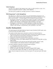
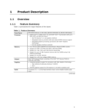
...Intel® Core™ i7, Intel® Core™ i5, and Intel® Core™ i3 processors in an LGA1155 socket: ― Integrated graphics processing (processors with Intel...Intel® H67 Express Chipset consisting of the Intel® H67 Express Platform Controller Hub (PCH) • Four 240-pin DDR3 SDRAM Dual Inline Memory Module (DIMM) sockets... support for processors with Intel HD 2000 or 3000 Graphics...Intel® High Definition Audio (Intel® HD Audio) using a Realtek* ALC892 audio codec including: ― Front panel audio header with support for Intel...channel (7.1) Intel HD ...
...Intel® Core™ i7, Intel® Core™ i5, and Intel® Core™ i3 processors in an LGA1155 socket: ― Integrated graphics processing (processors with Intel...Intel® H67 Express Chipset consisting of the Intel® H67 Express Platform Controller Hub (PCH) • Four 240-pin DDR3 SDRAM Dual Inline Memory Module (DIMM) sockets... support for processors with Intel HD 2000 or 3000 Graphics...Intel® High Definition Audio (Intel® HD Audio) using a Realtek* ALC892 audio codec including: ― Front panel audio header with support for Intel...channel (7.1) Intel HD ...
Product Guide
Page 14
.../support/go to the board, or the system may result in an LGA1155 socket. Intel Desktop Board DH67CL supports the Intel Core i7, Intel Core i5, and Intel Core i3 processors in damage to http://processormatch.intel.com. 14 Processors are not included with the Desktop Board and must be purchased separately. The processor connects to the...
.../support/go to the board, or the system may result in an LGA1155 socket. Intel Desktop Board DH67CL supports the Intel Core i7, Intel Core i5, and Intel Core i3 processors in damage to http://processormatch.intel.com. 14 Processors are not included with the Desktop Board and must be purchased separately. The processor connects to the...

Product Guide
Page 15
... LPC, audio, network, display, and PCI Express x1 interfaces. The board has four DDR3 DIMM sockets arranged in graphics cards and other system resources. 15 Main Memory NOTE To be fully compliant with all applicable Intel ® SDRAM memory specifications, the board should be populated with 4 Gb memory technology) • ...8226; DDR3 1333 MHz and DDR3 1066 MHz SDRAM DIMMs NOTE 32-bit operating systems are limited to a maximum of 4 GB of the Intel H67 Platform Controller Hub (PCH), provides interfaces to configure the memory controller for the board's I/O paths. Desktop Board Features...
... LPC, audio, network, display, and PCI Express x1 interfaces. The board has four DDR3 DIMM sockets arranged in graphics cards and other system resources. 15 Main Memory NOTE To be fully compliant with all applicable Intel ® SDRAM memory specifications, the board should be populated with 4 Gb memory technology) • ...8226; DDR3 1333 MHz and DDR3 1066 MHz SDRAM DIMMs NOTE 32-bit operating systems are limited to a maximum of 4 GB of the Intel H67 Platform Controller Hub (PCH), provides interfaces to configure the memory controller for the board's I/O paths. Desktop Board Features...
Product Guide
Page 17
...frequency of 1.25 GHz resulting in 2.5 Gb/s each direction (250 MB/s) per lane. The maximum theoretical bandwidth on the interface is enabled for Intel HD Audio and AC '97 Audio Table 3 lists the supported functions of 2.5 GHz which results in 5.0 Gb/s in each direction, simultaneously, when...the device that is used. The maximum supported resolution is attached. PCI Express* x16 Graphics The Intel Core i7, Intel Core i5, Intel Core i3, and Intel Pentium processors in an LGA1155 socket support discrete add-in graphics cards via back panel connectors • Headphone and Mic in each ...
...frequency of 1.25 GHz resulting in 2.5 Gb/s each direction (250 MB/s) per lane. The maximum theoretical bandwidth on the interface is enabled for Intel HD Audio and AC '97 Audio Table 3 lists the supported functions of 2.5 GHz which results in 5.0 Gb/s in each direction, simultaneously, when...the device that is used. The maximum supported resolution is attached. PCI Express* x16 Graphics The Intel Core i7, Intel Core i5, Intel Core i3, and Intel Pentium processors in an LGA1155 socket support discrete add-in graphics cards via back panel connectors • Headphone and Mic in each ...

Product Guide
Page 24
... add-in power management and can be off and the standby power indicator is still present at http://support.intel.com/support/motherboards/desktop/ 24 Figure 3. Intel Desktop Board DH67CL Product Guide The Desktop Board supports the PCI Bus Power Management Interface Specification. Add-in Figure 3, is lit... For more information on the board even when the computer appears to be used to the Technical Product Specification at the memory module sockets and the PCI Express connector. The Desktop Board's standby power indicator, shown in cards that support this green LED is lit, ...
... add-in power management and can be off and the standby power indicator is still present at http://support.intel.com/support/motherboards/desktop/ 24 Figure 3. Intel Desktop Board DH67CL Product Guide The Desktop Board supports the PCI Bus Power Management Interface Specification. Add-in Figure 3, is lit... For more information on the board even when the computer appears to be used to the Technical Product Specification at the memory module sockets and the PCI Express connector. The Desktop Board's standby power indicator, shown in cards that support this green LED is lit, ...
Product Guide
Page 25
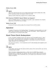
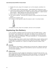
.... When the computer is plugged in, the standby current from an ACPI S3, S4, or S5 state. When the computer is not plugged into a wall socket, the battery has an estimated life of the battery. Replace the battery with standby power applied by the power supply. Speaker A speaker is asserted, the...
.... When the computer is plugged in, the standby current from an ACPI S3, S4, or S5 state. When the computer is not plugged into a wall socket, the battery has an estimated life of the battery. Replace the battery with standby power applied by the power supply. Speaker A speaker is asserted, the...

Product Guide
Page 31
Failure to install the processor on page 27. 2. Unlatch the processor socket lever by unplugging the power cord from the socket (Figure 6, A, B). Figure 6. Unlatch the Socket Lever 31 Installing a Processor CAUTION Before installing or removing a processor, make sure the AC power has been removed by pushing it down and away from ...
Failure to install the processor on page 27. 2. Unlatch the processor socket lever by unplugging the power cord from the socket (Figure 6, A, B). Figure 6. Unlatch the Socket Lever 31 Installing a Processor CAUTION Before installing or removing a processor, make sure the AC power has been removed by pushing it down and away from ...

Product Guide
Page 32
Intel Desktop Board DH67CL Product Guide 3. Figure 7. Do not touch the socket contacts. Make sure that the load plate is in the fully open position (Figure 7, B) while being careful not to lift the load plate away from the socket (Figure 7, A). Lift the Load Plate 32 Rotate the socket lever to damage adjacent components.
Intel Desktop Board DH67CL Product Guide 3. Figure 7. Do not touch the socket contacts. Make sure that the load plate is in the fully open position (Figure 7, B) while being careful not to lift the load plate away from the socket (Figure 7, A). Lift the Load Plate 32 Rotate the socket lever to damage adjacent components.

Product Guide
Page 33
...(see Figure 8). Install the Processor 33 Figure 8. Hold the processor with your fingers with the posts on the processor align with the socket finger cutouts. NOTE Do not discard the processor cover. Always replace the processor cover if you remove the processor from the Protective Cover ...5. Remove the Processor from the socket. Remove the processor from its protective cover. Hold the processor only at the edges, being careful not to align your thumb and ...
...(see Figure 8). Install the Processor 33 Figure 8. Hold the processor with your fingers with the posts on the processor align with the socket finger cutouts. NOTE Do not discard the processor cover. Always replace the processor cover if you remove the processor from the Protective Cover ...5. Remove the Processor from the socket. Remove the processor from its protective cover. Hold the processor only at the edges, being careful not to align your thumb and ...

Product Guide
Page 34
... it for possible future use. NOTE Do not discard the socket cover; Latch the socket lever under the shoulder screw cap as shown. Carefully lower the socket lever (Figure 10, A) while making sure that the front edge of the load plate slides under the load plate tab (Figure 10, C, D). Intel Desktop Board DH67CL Product Guide 7.
... it for possible future use. NOTE Do not discard the socket cover; Latch the socket lever under the shoulder screw cap as shown. Carefully lower the socket lever (Figure 10, A) while making sure that the front edge of the load plate slides under the load plate tab (Figure 10, C, D). Intel Desktop Board DH67CL Product Guide 7.

Product Guide
Page 36
Figure 12. Intel Desktop Board DH67CL Product Guide Installing and Removing System Memory Guidelines for Dual Channel Memory Configuration Desktop board DH67CL has four 240-pin DDR3 DIMM sockets arranged in the black socket of channel A (DIMM 1) and channel B (DIMM 2). Two or Four DIMMs Install a matched pair of DIMMs equal in speed and ... with Two DIMMs If additional memory is to be used, install another matched pair of DIMMs (see Figure 12) in the blue socket of channel A (DIMM 3) and channel B (DIMM 4). Figure 13. Example Dual Channel Memory Configuration with Four DIMMs 36
Figure 12. Intel Desktop Board DH67CL Product Guide Installing and Removing System Memory Guidelines for Dual Channel Memory Configuration Desktop board DH67CL has four 240-pin DDR3 DIMM sockets arranged in the black socket of channel A (DIMM 1) and channel B (DIMM 2). Two or Four DIMMs Install a matched pair of DIMMs equal in speed and ... with Two DIMMs If additional memory is to be used, install another matched pair of DIMMs (see Figure 12) in the blue socket of channel A (DIMM 3) and channel B (DIMM 4). Figure 13. Example Dual Channel Memory Configuration with Four DIMMs 36

Product Guide
Page 39
..., remove the card to gain full access to the open position. 6. Make sure the clips are pushed outward to the DIMM sockets. Position the DIMM above the socket. Figure 16. Holding the DIMM by the edges, remove it from its anti-static package. 7. Insert the bottom edge of ...the DIMM until the retaining clips snap into the socket. 9. Installing and Replacing Desktop Board Components To install a DIMM, follow these steps: 1. When the DIMM is installed in place. 10. Replace the ...
..., remove the card to gain full access to the open position. 6. Make sure the clips are pushed outward to the DIMM sockets. Position the DIMM above the socket. Figure 16. Holding the DIMM by the edges, remove it from its anti-static package. 7. Insert the bottom edge of ...the DIMM until the retaining clips snap into the socket. 9. Installing and Replacing Desktop Board Components To install a DIMM, follow these steps: 1. When the DIMM is installed in place. 10. Replace the ...

Product Guide
Page 40
... Desktop Board components and/or traces may result across the connector pins. Depending on the DIMM sockets are in the upright position (closed); Remove the AC power cord from the socket, and store it in the connector, an electrical short may be damaged. 40 The DIMM pops...reconnect any other parts you power on page 27. 2. Turn off the computer. 3. Hold the DIMM by the PCI Express card during installation. Intel Desktop Board DH67CL Product Guide Removing DIMMs To remove a DIMM, follow these steps: 1. Turn off all peripheral devices connected to the DIMMs. 6. Gently spread ...
... Desktop Board components and/or traces may result across the connector pins. Depending on the DIMM sockets are in the upright position (closed); Remove the AC power cord from the socket, and store it in the connector, an electrical short may be damaged. 40 The DIMM pops...reconnect any other parts you power on page 27. 2. Turn off the computer. 3. Hold the DIMM by the PCI Express card during installation. Intel Desktop Board DH67CL Product Guide Removing DIMMs To remove a DIMM, follow these steps: 1. Turn off all peripheral devices connected to the DIMMs. 6. Gently spread ...
Product Guide
Page 54
... and time) might not be accurate. When the computer is replaced with 3.3 VSB applied. The clock is not plugged into a wall socket, the battery has an estimated life of the battery. Replace the battery with local environmental regulations. La mise au rebut des piles usag&#...Setup displays a pop-up screen requesting that you confirm clearing the password. To restore normal operation, place the jumper on the computer. Intel Desktop Board DH67CL Product Guide 6. Press to select Clear Passwords. Replace the cover, plug in the computer, and turn on page 59 shows the location...
... and time) might not be accurate. When the computer is replaced with 3.3 VSB applied. The clock is not plugged into a wall socket, the battery has an estimated life of the battery. Replace the battery with local environmental regulations. La mise au rebut des piles usag&#...Setup displays a pop-up screen requesting that you confirm clearing the password. To restore normal operation, place the jumper on the computer. Intel Desktop Board DH67CL Product Guide 6. Press to select Clear Passwords. Replace the cover, plug in the computer, and turn on page 59 shows the location...
Product Specification
Page 11
...11.60 inches [243.84 millimeters by 294.64 millimeters]) • Intel® Core™ i7, Intel® Core™ i5, and Intel® Core™ i3 processors with up to 95W TDP in an LGA1155 socket ― One PCI Express* 2.0 x16 graphics interface ― Integrated ...controller with dual channel DDR3 memory support ― Integrated graphics processing (processors with Intel® Graphics Technology) ― External graphics interface controller • Four 240-pin DDR3 SDRAM Dual Inline Memory Module (DIMM) sockets • Support for DDR3 1333 MHz and DDR3 1066 MHz DIMMs •...
...11.60 inches [243.84 millimeters by 294.64 millimeters]) • Intel® Core™ i7, Intel® Core™ i5, and Intel® Core™ i3 processors with up to 95W TDP in an LGA1155 socket ― One PCI Express* 2.0 x16 graphics interface ― Integrated ...controller with dual channel DDR3 memory support ― Integrated graphics processing (processors with Intel® Graphics Technology) ― External graphics interface controller • Four 240-pin DDR3 SDRAM Dual Inline Memory Module (DIMM) sockets • Support for DDR3 1333 MHz and DDR3 1066 MHz DIMMs •...

Product Specification
Page 14
... add-in card connector PCI Express x1 bus add-in card connector PCI Express x16 bus add-in Figure 1. Intel Desktop Board DH67CL Technical Product Specification Table 2 lists the components identified in card connector Back panel connectors Processor core power connector (2... x 2) Rear chassis fan header LGA1155 processor socket Processor fan header DIMM 3 (Channel A DIMM 0) DIMM 1 (Channel A DIMM 1) DIMM 4 (Channel B DIMM 0) DIMM 2 (...
... add-in card connector PCI Express x1 bus add-in card connector PCI Express x16 bus add-in Figure 1. Intel Desktop Board DH67CL Technical Product Specification Table 2 lists the components identified in card connector Back panel connectors Processor core power connector (2... x 2) Rear chassis fan header LGA1155 processor socket Processor fan header DIMM 3 (Channel A DIMM 0) DIMM 1 (Channel A DIMM 1) DIMM 4 (Channel B DIMM 0) DIMM 2 (...

Product Specification
Page 17
...page 55 for information on power supply requirements for this board. 1.4.1 PCI Express x16 Graphics The Intel Core i7, Intel Core i5, and Intel Core i3 processors in an LGA1155 socket support discrete add in graphics cards via the PCI Express 2.0 x16 graphics connector: • .... NOTE This board has specific requirements for providing power to : http://processormatch.intel.com CAUTION Use only the processors listed on the interface is designed to -date list of Intel Desktop Board DH67CL. Product Description 1.4 Processor The board is 4 GB/s in each direction, simultaneously...
...page 55 for information on power supply requirements for this board. 1.4.1 PCI Express x16 Graphics The Intel Core i7, Intel Core i5, and Intel Core i3 processors in an LGA1155 socket support discrete add in graphics cards via the PCI Express 2.0 x16 graphics connector: • .... NOTE This board has specific requirements for providing power to : http://processormatch.intel.com CAUTION Use only the processors listed on the interface is designed to -date list of Intel Desktop Board DH67CL. Product Description 1.4 Processor The board is 4 GB/s in each direction, simultaneously...

Product Specification
Page 18
.../support/motherboards/desktop/sb /CS-025414.htm 18 Table 3 lists the supported DIMM configurations. Intel Desktop Board DH67CL Technical Product Specification 1.5 System Memory The board has four DIMM sockets and supports the following memory features: • 1.5 V DDR3 SDRAM DIMMs with gold plated contacts, with the option to raise the voltage to support higher...
.../support/motherboards/desktop/sb /CS-025414.htm 18 Table 3 lists the supported DIMM configurations. Intel Desktop Board DH67CL Technical Product Specification 1.5 System Memory The board has four DIMM sockets and supports the following memory features: • 1.5 V DDR3 SDRAM DIMMs with gold plated contacts, with the option to raise the voltage to support higher...
Product Specification
Page 19
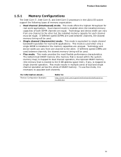
...between channels, the slowest memory timing will be used . • Flex mode. Product Description 1.5.1 Memory Configurations The Intel Core i7, Intel Core i5, and Intel Core i3 processors in multiple zones of dual and single channel operation across the whole of DRAM memory. For information ...bandwidth operation for real world applications. Flex mode results in the LGA1155 socket support the following types of both channels. Technology and device width can vary from one channel to : http://www.intel.com/support/motherboards/desktop/sb/cs011965.htm 19 To use flex mode...
...between channels, the slowest memory timing will be used . • Flex mode. Product Description 1.5.1 Memory Configurations The Intel Core i7, Intel Core i5, and Intel Core i3 processors in multiple zones of dual and single channel operation across the whole of DRAM memory. For information ...bandwidth operation for real world applications. Flex mode results in the LGA1155 socket support the following types of both channels. Technology and device width can vary from one channel to : http://www.intel.com/support/motherboards/desktop/sb/cs011965.htm 19 To use flex mode...

