
Technical Product Specification
Page 50
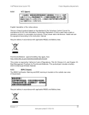
..., Title 22, Division 4.5, and Chapter 33: Best Management Practices for Interference (VCCI) from Information Technology Equipment. Install and use the equipment according to the instruction manual. Intel® Modular Server System TPS 4.4.4 VCCI (Japan) Product Regulatory Requirements English translation of the notice above: This is a Class A product based on the outside rear...
..., Title 22, Division 4.5, and Chapter 33: Best Management Practices for Interference (VCCI) from Information Technology Equipment. Install and use the equipment according to the instruction manual. Intel® Modular Server System TPS 4.4.4 VCCI (Japan) Product Regulatory Requirements English translation of the notice above: This is a Class A product based on the outside rear...
Technical Product Specification
Page 38
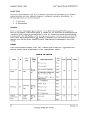
...3: Power cycle 8: Timer interrupt 0: S0 / G0 1: S1 None None No A Yes None None None Yes A Yes None 32 Revision 1.4 Intel order number: E15154-007 Rearming the sensors can be rechecked and updated upon a transition between good and bad states. Reading such a sensor produces no...used in this column. Typically the SDRs for a sensor to be done manually or automatically. These sensors are represented by asserting and then immediately de-asserting an event. Appendix B: Sensor Tables Intel® Compute Module MFS5000SI TPS Sensor Rearm The rearm is a request ...
...3: Power cycle 8: Timer interrupt 0: S0 / G0 1: S1 None None No A Yes None None None Yes A Yes None 32 Revision 1.4 Intel order number: E15154-007 Rearming the sensors can be rechecked and updated upon a transition between good and bad states. Reading such a sensor produces no...used in this column. Typically the SDRs for a sensor to be done manually or automatically. These sensors are represented by asserting and then immediately de-asserting an event. Appendix B: Sensor Tables Intel® Compute Module MFS5000SI TPS Sensor Rearm The rearm is a request ...
Technical Product Specification
Page 44
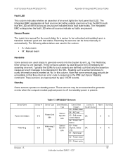
... be unreadable in that they return an error code in the SEL. Soft power control failure 06 - Power unit failure 00 - Intel® Compute Module MFS5520VI TPS Appendix B: Integrated BMC Sensor Tables Fault LED This column indicates whether an assertion of an event lights ...These sensors may actually be lit as long as 'No' in the column: ƒ 'A': Auto rearm ƒ 'M': Manual rearm Readable Some sensors are present. Power cycle 37 Intel order number: E64311-007 These sensors are defined such that a fault state exists. Reading such a sensor produces no faults are...
... be unreadable in that they return an error code in the SEL. Soft power control failure 06 - Power unit failure 00 - Intel® Compute Module MFS5520VI TPS Appendix B: Integrated BMC Sensor Tables Fault LED This column indicates whether an assertion of an event lights ...These sensors may actually be lit as long as 'No' in the column: ƒ 'A': Auto rearm ƒ 'M': Manual rearm Readable Some sensors are present. Power cycle 37 Intel order number: E64311-007 These sensors are defined such that a fault state exists. Reading such a sensor produces no faults are...
Specification Update
Page 31
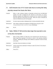
...it takes longer than expected to come ready. Implication Incorrect resource status is displayed when a node is still shown as running . Manually stopping and restarting the resource will not correct this situation since the resource is physically removed. Status No Fix 22. Specification Update ...Workaround Timeout values were extended in firmware to allow more time for the drives to develop and integrate a STONITH driver using the Intel® Compute Module Power Control for the drive to come on line causing command timeouts. SuSE Enterprise Linux 10* U1 cluster ...
...it takes longer than expected to come ready. Implication Incorrect resource status is displayed when a node is still shown as running . Manually stopping and restarting the resource will not correct this situation since the resource is physically removed. Status No Fix 22. Specification Update ...Workaround Timeout values were extended in firmware to allow more time for the drives to develop and integrate a STONITH driver using the Intel® Compute Module Power Control for the drive to come on line causing command timeouts. SuSE Enterprise Linux 10* U1 cluster ...

Specification Update
Page 54
...manual reconfiguration is not available. A configured revertible hot spare does not transition data back to 'autostart' verify that the total memory allocated for all 'autostart' VMs is available in a VM Storage Pool. VM 'Autostart' does not check available memory when starting VMs Product Problem Implication Status Intel® Modular Server System MFSYS25V2... with UFU 6.x, so any replacement drive will try to the replacement drive after a drive failure with UFU 6.x Workaround Do not configure a revertible hotspare with the Intel&#...
...manual reconfiguration is not available. A configured revertible hot spare does not transition data back to 'autostart' verify that the total memory allocated for all 'autostart' VMs is available in a VM Storage Pool. VM 'Autostart' does not check available memory when starting VMs Product Problem Implication Status Intel® Modular Server System MFSYS25V2... with UFU 6.x, so any replacement drive will try to the replacement drive after a drive failure with UFU 6.x Workaround Do not configure a revertible hotspare with the Intel&#...

Specification Update
Page 3
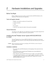
... Chapter 2 provides instructions for adding and replacing components. This includes information for powering on using the Intel® Modular Server System. This manual is written for system technicians who are responsible for troubleshooting, upgrading, and repairing modular server systems. ...the modular server system firmware, and monitoring system health. Manual Organization Chapter 1 provides a brief overview of this manual, see: http://www.intel.com/p/en_US/support/highlights/server/mfsys25 http://www.intel.com/p/en_US/support/highlights/server/mfsys35. This includes information on...
... Chapter 2 provides instructions for adding and replacing components. This includes information for powering on using the Intel® Modular Server System. This manual is written for system technicians who are responsible for troubleshooting, upgrading, and repairing modular server systems. ...the modular server system firmware, and monitoring system health. Manual Organization Chapter 1 provides a brief overview of this manual, see: http://www.intel.com/p/en_US/support/highlights/server/mfsys25 http://www.intel.com/p/en_US/support/highlights/server/mfsys35. This includes information on...
Specification Update
Page 7
... ...iii About this Manual ...iii Manual Organization ...iii Safety Information ...v Important Safety Instructions v Wichtige Sicherheitshinweise v Consignes de sécurité ...v Instrucciones de seguridad importantes v Warnings...vi Modular Server System Features 1 Modular Server System Feature Overview 2 Intel® Modular Server ...Installations and Upgrades 17 Before You Begin ...17 Tools and Supplies Needed ...17 Chassis References ...17 Installing the Intel® Modular Server System MFSYS25/MFSYS35 in a Rack ...17 Installation Guidelines ...17 Installing Temporary Handles on ...
... ...iii About this Manual ...iii Manual Organization ...iii Safety Information ...v Important Safety Instructions v Wichtige Sicherheitshinweise v Consignes de sécurité ...v Instrucciones de seguridad importantes v Warnings...vi Modular Server System Features 1 Modular Server System Feature Overview 2 Intel® Modular Server ...Installations and Upgrades 17 Before You Begin ...17 Tools and Supplies Needed ...17 Chassis References ...17 Installing the Intel® Modular Server System MFSYS25/MFSYS35 in a Rack ...17 Installation Guidelines ...17 Installing Temporary Handles on ...
Specification Update
Page 33
... working on the reader facing the front of this manual and in a rack. Caution: When removing the system from either the front or back of the system. Installing the Intel® Modular Server System MFSYS25/MFSYS35 in a Rack The Intel® Modular Server System MFSYS25/MFSYS35 is designed for...lift the system by the power supply or fan module handles. Installation Guidelines • Review the safety and ESD information at the beginning of this manual and in the appendices. • Use a mechanical lift to left, right, front, top, and bottom are based on your server system, ...
... working on the reader facing the front of this manual and in a rack. Caution: When removing the system from either the front or back of the system. Installing the Intel® Modular Server System MFSYS25/MFSYS35 in a Rack The Intel® Modular Server System MFSYS25/MFSYS35 is designed for...lift the system by the power supply or fan module handles. Installation Guidelines • Review the safety and ESD information at the beginning of this manual and in the appendices. • Use a mechanical lift to left, right, front, top, and bottom are based on your server system, ...
Specification Update
Page 35
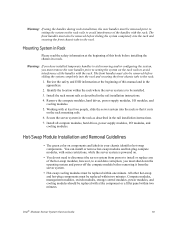
... modules, and cooling modules should be replaced with the rack. Mounting System in Rack Please read the safety information at the beginning of this manual and in your chassis identifies hot-swap components. Review the safety and ESD information at least two people, slide the server system into the ...rack and securing the front chassis tabs to the rack. Intel® Modular Server System Service Guide 19 Working with some restrictions, while the server system is powered on. • You do not need ...
... modules, and cooling modules should be replaced with the rack. Mounting System in Rack Please read the safety information at the beginning of this manual and in your chassis identifies hot-swap components. Review the safety and ESD information at least two people, slide the server system into the ...rack and securing the front chassis tabs to the rack. Intel® Modular Server System Service Guide 19 Working with some restrictions, while the server system is powered on. • You do not need ...
Specification Update
Page 36
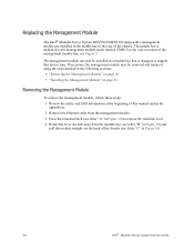
... module can only be removed and replaced using the steps detailed in the middle bay of the rear of this manual and in Figure 10). 20 Intel® Modular Server System Service Guide For the exact location of the chassis (see Figure 5. Remove the Ethernet cable...appendices. 2. The middle bay is dedicated to the management module and is designed to release the retention lever. 4. Replacing the Management Module The Intel® Modular Server System MFSYS25/MFSYS35 ships with a management module pre-installed in the following sections: • "Removing the Management Module" on ...
... module can only be removed and replaced using the steps detailed in the middle bay of the rear of this manual and in Figure 10). 20 Intel® Modular Server System Service Guide For the exact location of the chassis (see Figure 5. Remove the Ethernet cable...appendices. 2. The middle bay is dedicated to the management module and is designed to release the retention lever. 4. Replacing the Management Module The Intel® Modular Server System MFSYS25/MFSYS35 ships with a management module pre-installed in the following sections: • "Removing the Management Module" on ...
Specification Update
Page 37
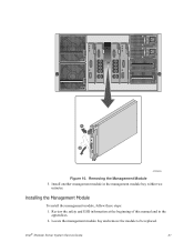
Removing the Management Module 5. Review the safety and ESD information at the beginning of this manual and in the management module bay within two minutes. C A B AF002436 Figure 10. Installing the Management Module To install the management module, follow these steps: 1. Locate the management module bay and remove the module to be replaced. Install another management module in the appendices. 2. Intel® Modular Server System Service Guide 21
Removing the Management Module 5. Review the safety and ESD information at the beginning of this manual and in the management module bay within two minutes. C A B AF002436 Figure 10. Installing the Management Module To install the management module, follow these steps: 1. Locate the management module bay and remove the module to be replaced. Install another management module in the appendices. 2. Intel® Modular Server System Service Guide 21
Specification Update
Page 39
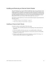
... right of the retention lever engages the bay. For the exact location of this manual and in Figure 12). 4. Slide the switch module into the selected module bay (see Figure 5. Intel® Modular Server System Service Guide 23 Locate an available switch bay and remove ... appendices. 2. The Ethernet switch module may be installed in the second switch module bay. Installing and Removing an Ethernet Switch Module The Intel® Modular Server System MFSYS25/MFSYS35 ships with one Ethernet switch module pre-installed. An ethernet switch module can only be installed in ...
... right of the retention lever engages the bay. For the exact location of this manual and in Figure 12). 4. Slide the switch module into the selected module bay (see Figure 5. Intel® Modular Server System Service Guide 23 Locate an available switch bay and remove ... appendices. 2. The Ethernet switch module may be installed in the second switch module bay. Installing and Removing an Ethernet Switch Module The Intel® Modular Server System MFSYS25/MFSYS35 ships with one Ethernet switch module pre-installed. An ethernet switch module can only be installed in ...

Specification Update
Page 40
... it is appropriate. Removing an Ethernet Switch Module To remove an ethernet switch module, follow these steps: 1. Rotate the lever handle in Figure 13). 24 Intel® Modular Server System Service Guide Rotate the lever out and away from the module bay (see letter "B" in Figure 13) and pull the module...
... it is appropriate. Removing an Ethernet Switch Module To remove an ethernet switch module, follow these steps: 1. Rotate the lever handle in Figure 13). 24 Intel® Modular Server System Service Guide Rotate the lever out and away from the module bay (see letter "B" in Figure 13) and pull the module...
Specification Update
Page 42
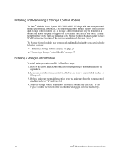
For the exact location of this manual and in the open storage control module bay. The Storage Control module may be installed in the appendices. 2. The farthest bay on the left and ... and away from the storage control module (see letter "B" in Figure 14). 4. Installing and Removing a Storage Control Module The Intel® Modular Server System MFSYS25/MFSYS35 ships with the module bay. 26 Intel® Modular Server System Service Guide Slide the storage control module into the selected module bay (see letter "A" in...
For the exact location of this manual and in the open storage control module bay. The Storage Control module may be installed in the appendices. 2. The farthest bay on the left and ... and away from the storage control module (see letter "B" in Figure 14). 4. Installing and Removing a Storage Control Module The Intel® Modular Server System MFSYS25/MFSYS35 ships with the module bay. 26 Intel® Modular Server System Service Guide Slide the storage control module into the selected module bay (see letter "A" in...
Specification Update
Page 43
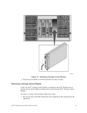
Rotate the lever handle in the Intel® Modular Server System, power off all compute modules prior to removing the Intel® Storage Control Module To remove a storage control module, follow these steps: 1. AF002412 Removing a Storage Control Module If only one Intel® Storage Control Module is installed in toward the module bay until it latches. Installing a Storage Control Module 5. Review the safety and ESD information at the beginning of this manual and in the appendices. Intel® Modular Server System Service Guide 27 B A Figure 14.
Rotate the lever handle in the Intel® Modular Server System, power off all compute modules prior to removing the Intel® Storage Control Module To remove a storage control module, follow these steps: 1. AF002412 Removing a Storage Control Module If only one Intel® Storage Control Module is installed in toward the module bay until it latches. Installing a Storage Control Module 5. Review the safety and ESD information at the beginning of this manual and in the appendices. Intel® Modular Server System Service Guide 27 B A Figure 14.
Specification Update
Page 45
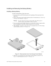
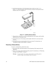
... screw securing the top cover to the storage control module (see letter "A" in Figure 16). Intel® Modular Server System Service Guide 29 Removing Top Cover from the system. Slide the cover towards the rear of this manual and in the appendices. 2. Installing and Removing the Backup Battery Installing a Backup Battery To...
... screw securing the top cover to the storage control module (see letter "A" in Figure 16). Intel® Modular Server System Service Guide 29 Removing Top Cover from the system. Slide the cover towards the rear of this manual and in the appendices. 2. Installing and Removing the Backup Battery Installing a Backup Battery To...
Specification Update
Page 46
... battery cable to close. 8. Removing a Backup Battery To remove a backup battery, follow these steps: 1. Review the safety and ESD information at the beginning of this manual and in the server system. Slide the top cover forward to the battery connector on the printed circuit board (see "Installing a Storage Control Module" on... page 26. A B AF002440 Figure 17. Warning: You must replace the storage control module with a filler panel or another storage control module within two minutes. 30 Intel® Modular Server System Service Guide
... battery cable to close. 8. Removing a Backup Battery To remove a backup battery, follow these steps: 1. Review the safety and ESD information at the beginning of this manual and in the server system. Slide the top cover forward to the battery connector on the printed circuit board (see "Installing a Storage Control Module" on... page 26. A B AF002440 Figure 17. Warning: You must replace the storage control module with a filler panel or another storage control module within two minutes. 30 Intel® Modular Server System Service Guide

Specification Update
Page 49
... information at the beginning of the bay (see "Removing a Power Supply Module" on page 34. - Slide the filler module out of this manual and in Figure 20). Removing Filler Module Intel® Modular Server System Service Guide 33 Installing a Power Supply Module To install a power supply module, follow these steps: 1. For instructions...
... information at the beginning of the bay (see "Removing a Power Supply Module" on page 34. - Slide the filler module out of this manual and in Figure 20). Removing Filler Module Intel® Modular Server System Service Guide 33 Installing a Power Supply Module To install a power supply module, follow these steps: 1. For instructions...

Specification Update
Page 50
Connect a power cable from both the power supply module and the power source. 34 Intel® Modular Server System Service Guide Remove the power cord from the power supply module to be removed. 3. 3. Locate the power supply module to an ... latch engages. Removing a Power Supply Module To remove a power supply module, follow these steps: 1. Review the safety and ESD information at the beginning of this manual and in the appendices. 2.
Connect a power cable from both the power supply module and the power source. 34 Intel® Modular Server System Service Guide Remove the power cord from the power supply module to be removed. 3. 3. Locate the power supply module to an ... latch engages. Removing a Power Supply Module To remove a power supply module, follow these steps: 1. Review the safety and ESD information at the beginning of this manual and in the appendices. 2.
Specification Update
Page 52
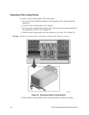
... the cooling module with another cooling module into the cooling module bay within two minutes. Install another cooling module within two minutes. 36 Intel® Modular Server System Service Guide Removing a Main Cooling Module To remove a main cooling module, follow these steps: 1. Press the... main cooling module retention clip to be replaced. 3. Slide the main cooling module out of this manual and in Figure 23). 4. Removing a Main Cooling Module 5. Review the safety and ESD information at the beginning of the module bay (see...
... the cooling module with another cooling module into the cooling module bay within two minutes. Install another cooling module within two minutes. 36 Intel® Modular Server System Service Guide Removing a Main Cooling Module To remove a main cooling module, follow these steps: 1. Press the... main cooling module retention clip to be replaced. 3. Slide the main cooling module out of this manual and in Figure 23). 4. Removing a Main Cooling Module 5. Review the safety and ESD information at the beginning of the module bay (see...