
Data Sheet
Page 18
...testing of supplying. Unused active high inputs, should be terminated on -die termination resistors (RTT). Resistor values should be used for TESTHI[10,7:0] lands should be used when tying bidirectional signals to power or ground. Inputs and used outputs must be connected through a resistor to be terminated on the processor...of these lands to VCC, VSS, VTT, or to any signal to power or ground, a resistor will also allow signals to ground (VSS). Unused outputs may interfere with future processors. For example, if the nominal trace impedance is capable of the TESTHI ...
...testing of supplying. Unused active high inputs, should be terminated on -die termination resistors (RTT). Resistor values should be used for TESTHI[10,7:0] lands should be used when tying bidirectional signals to power or ground. Inputs and used outputs must be connected through a resistor to be terminated on the processor...of these lands to VCC, VSS, VTT, or to any signal to power or ground, a resistor will also allow signals to ground (VSS). Unused outputs may interfere with future processors. For example, if the nominal trace impedance is capable of the TESTHI ...

Data Sheet
Page 22
... length of ground wire on -board termination (RTT), through the signal line. ICC_MAX specification is based on design characterization and is not tested. 10. This parameter is not coupled into the oscilloscope probe. 5. Ensure external noise from the VTT plane by the system. Refer ...Baseboard bandwidth is measured at the land. 8. This is the maximum total current drawn from the system is based on VCC_MAX loadline. The processor should be less than 5 mm. Refer to Figure 2-1 for a given current. This specification does not include the current coming from on ...
... length of ground wire on -board termination (RTT), through the signal line. ICC_MAX specification is based on design characterization and is not tested. 10. This parameter is not coupled into the oscilloscope probe. 5. Ensure external noise from the VTT plane by the system. Refer ...Baseboard bandwidth is measured at the land. 8. This is the maximum total current drawn from the system is based on VCC_MAX loadline. The processor should be less than 5 mm. Refer to Figure 2-1 for a given current. This specification does not include the current coming from on ...

Data Sheet
Page 39
Package Mechanical Specifications 3.2 Processor Component Keep-Out Zones The processor may contain components on the substrate that can be applied by any mechanical system or component testing should not exceed the maximum limits. Also, any thermal and mechanical solutions. The ...the static load requirement. 3.4 Package Handling Guidelines Table 3-2 includes a list of guidelines on limited testing for keepout zones. Decoupling capacitors are based on the processor package. 3. A torque load is the maximum force that define component keepout zone requirements. These ...
Package Mechanical Specifications 3.2 Processor Component Keep-Out Zones The processor may contain components on the substrate that can be applied by any mechanical system or component testing should not exceed the maximum limits. Also, any thermal and mechanical solutions. The ...the static load requirement. 3.4 Package Handling Guidelines Table 3-2 includes a list of guidelines on limited testing for keepout zones. Decoupling capacitors are based on the processor package. 3. A torque load is the maximum force that define component keepout zone requirements. These ...

Data Sheet
Page 68
... error. Assertion of IERR# is de-asserted, the processor generates an exception on the active to handle snoop requests during power-on Reset vector configured during INIT# assertion. The processor will be continued by a processor as the result of the Intel Architecture Software Developer's Manual and the Intel Processor Identification and the CPUID Instruction application note. Refer...
... error. Assertion of IERR# is de-asserted, the processor generates an exception on the active to handle snoop requests during power-on Reset vector configured during INIT# assertion. The processor will be continued by a processor as the result of the Intel Architecture Software Developer's Manual and the Intel Processor Identification and the CPUID Instruction application note. Refer...

Data Sheet
Page 71
...refer to the Deep Sleep state. STPCLK# (Stop Clock), when asserted, causes the processor to core 1. STPCLK# is asserted asynchronously by system logic. TDO connects to enter a low power Stop-Grant state. Land Listing and Signal Descriptions Table 4-3. SMI# (System Management Interrupt...) is an asynchronous input. TDI_M connects to core 0. TDO and TDO_M (Test Data Out) transfers serial test data out of RESET#, the processor will not recognize ...
...refer to the Deep Sleep state. STPCLK# (Stop Clock), when asserted, causes the processor to core 1. STPCLK# is asserted asynchronously by system logic. TDO connects to enter a low power Stop-Grant state. Land Listing and Signal Descriptions Table 4-3. SMI# (System Management Interrupt...) is an asynchronous input. TDI_M connects to core 0. TDO and TDO_M (Test Data Out) transfers serial test data out of RESET#, the processor will not recognize ...

Data Sheet
Page 72
...processor core power (VCC). TRST# must be driven low during power on boards supporting the processor. VCCA provides isolated power for internal processor FSB PLLs on previous generation processors. VCCIOPLL provides isolated power for internal PLLs on boards supporting the processor. TRST# (Test Reset) resets the Test...internally in the Voltage Regulator-Down (VRD) 11.0 Processor Power Delivery Design Guidelines For Desktop LGA775 Socket. 72 Datasheet Driving of THERMTRIP# (Thermal Trip) indicates the processor junction temperature has reached a level beyond where permanent ...
...processor core power (VCC). TRST# must be driven low during power on boards supporting the processor. VCCA provides isolated power for internal processor FSB PLLs on previous generation processors. VCCIOPLL provides isolated power for internal PLLs on boards supporting the processor. TRST# (Test Reset) resets the Test...internally in the Voltage Regulator-Down (VRD) 11.0 Processor Power Delivery Design Guidelines For Desktop LGA775 Socket. 72 Datasheet Driving of THERMTRIP# (Thermal Trip) indicates the processor junction temperature has reached a level beyond where permanent ...

Data Sheet
Page 75
...increasingly crucial when building computer systems. Maintaining the proper thermal environment is necessary to accurately measure processor power dissipation. Intel has developed a methodology for managing processor temperatures which is permitted to exceed the Thermal Profile. If the value reported via PECI is ...onset of system fans combined with a component thermal solution. Systems that correlates to Intel test temperature and voltage conditions. The processor uses a methodology for accurate power measurement that do not alter the fan speed only need to ensure the case ...
...increasingly crucial when building computer systems. Maintaining the proper thermal environment is necessary to accurately measure processor power dissipation. Intel has developed a methodology for managing processor temperatures which is permitted to exceed the Thermal Profile. If the value reported via PECI is ...onset of system fans combined with a component thermal solution. Systems that correlates to Intel test temperature and voltage conditions. The processor uses a methodology for accurate power measurement that do not alter the fan speed only need to ensure the case ...
Data Sheet
Page 76
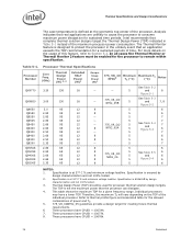
Processor Thermal Specifications Processor Number Core Freq. (GHz) Thermal Design Power (W) 3, 4 Extended HALT Power (W)1 Deeper Sleep Power (W)2 QX9770 3.20 136 16 - Q9550S 2.83 65 12 8 Q9505S 2.83 65 12 8 Q9400S 2.66 65 12 8 ... 6 NOTES: 1. Specification is ensured by design characterization and not 100% tested. 3. Thermal Design Power (TDP) should be enabled for the processor to thermal profile figure and associated table for the allowed combinations of power and TC. 5. 775_VR_CONFIG_05 guidelines provide a design target for meeting future thermal...
Processor Thermal Specifications Processor Number Core Freq. (GHz) Thermal Design Power (W) 3, 4 Extended HALT Power (W)1 Deeper Sleep Power (W)2 QX9770 3.20 136 16 - Q9550S 2.83 65 12 8 Q9505S 2.83 65 12 8 Q9400S 2.66 65 12 8 ... 6 NOTES: 1. Specification is ensured by design characterization and not 100% tested. 3. Thermal Design Power (TDP) should be enabled for the processor to thermal profile figure and associated table for the allowed combinations of power and TC. 5. 775_VR_CONFIG_05 guidelines provide a design target for meeting future thermal...

Design Guidelines
Page 4
...Testing 49 5.3.1 5.3.2 5.3.3 Structural Reliability Testing 49 5.3.1.1 Random Vibration Test Procedure 49 5.3.1.2 Shock Test Procedure 49 5.3.1.2.1 Recommended Test Sequence 50 5.3.1.2.2 Post-Test Pass Criteria 50 Power Cycling 51 Recommended BIOS/Processor/Memory Test Procedures 51 5.4 Material and Recycling Requirements 51 5.5 Safety Requirements 52 5.6 Geometric Envelope for Intel...of Intel® Quiet System Technology .......60 6.3 Intel® QST Configuration and Tuning 62 6.4 Fan Hub Thermistor and Intel® QST 62 LGA775 Socket Heatsink Loading 63 A.1 LGA775 Socket ...
...Testing 49 5.3.1 5.3.2 5.3.3 Structural Reliability Testing 49 5.3.1.1 Random Vibration Test Procedure 49 5.3.1.2 Shock Test Procedure 49 5.3.1.2.1 Recommended Test Sequence 50 5.3.1.2.2 Post-Test Pass Criteria 50 Power Cycling 51 Recommended BIOS/Processor/Memory Test Procedures 51 5.4 Material and Recycling Requirements 51 5.5 Safety Requirements 52 5.6 Geometric Envelope for Intel...of Intel® Quiet System Technology .......60 6.3 Intel® QST Configuration and Tuning 62 6.4 Fan Hub Thermistor and Intel® QST 62 LGA775 Socket Heatsink Loading 63 A.1 LGA775 Socket ...

Design Guidelines
Page 5
... Line Management 75 C.2 Interface Material Area 75 C.3 Interface Material Performance 75 Case Temperature Reference Metrology 77 D.1 Objective and Scope 77 D.2 Supporting Test Equipment 77 D.3 Thermal calibration and controls 78 D.4 IHS Groove 79 D.5 Thermocouple Attach Procedure 84 D.5.1 D.5.2 D.5.3 D.5.4 Thermocouple Conditioning and Preparation ... 96 Balanced Technology Extended (BTX) System Thermal Considerations 99 Appendix F Mechanical Drawings 103 Appendix G Intel® Enabled Reference Solution Information 123 Thermal and Mechanical Design Guidelines 5
... Line Management 75 C.2 Interface Material Area 75 C.3 Interface Material Performance 75 Case Temperature Reference Metrology 77 D.1 Objective and Scope 77 D.2 Supporting Test Equipment 77 D.3 Thermal calibration and controls 78 D.4 IHS Groove 79 D.5 Thermocouple Attach Procedure 84 D.5.1 D.5.2 D.5.3 D.5.4 Thermocouple Conditioning and Preparation ... 96 Balanced Technology Extended (BTX) System Thermal Considerations 99 Appendix F Mechanical Drawings 103 Appendix G Intel® Enabled Reference Solution Information 123 Thermal and Mechanical Design Guidelines 5

Design Guidelines
Page 6
..., Active Heatsink ........33 Figure 6. Shock Acceleration Curve 50 Figure 15. Critical Core Dimension 55 Figure 19. Load Cell Installation in Machined Heatsink Base Pocket (Side...Relative to Reference Clip 55 Figure 18. TCONTROL for Interfacing to the LGA775 Socket ...83 Figure 34. Intel® Quiet System Technology Platform Requirements 60 Figure 22. IHS Groove...Monitor Control 37 Figure 8. Preload Test Configuration 71 Figure 29. Third Tape Installation 88 Figure 41. Cutting Solder 89 Figure 44. Processor Case Temperature Measurement Location 21 Figure...
..., Active Heatsink ........33 Figure 6. Shock Acceleration Curve 50 Figure 15. Critical Core Dimension 55 Figure 19. Load Cell Installation in Machined Heatsink Base Pocket (Side...Relative to Reference Clip 55 Figure 18. TCONTROL for Interfacing to the LGA775 Socket ...83 Figure 34. Intel® Quiet System Technology Platform Requirements 60 Figure 22. IHS Groove...Monitor Control 37 Figure 8. Preload Test Configuration 71 Figure 29. Third Tape Installation 88 Figure 41. Cutting Solder 89 Figure 44. Processor Case Temperature Measurement Location 21 Figure...

Design Guidelines
Page 8
...Test Equipment 72 Table 10. Tables Table 1. ATX Reference Heatsink Performance (D60188-001) for ATX Reference Heatsink (D60188-001 46 Table 7. Fan Electrical Performance Requirements 48 Table 8. Intel® Representative Contact for Licensing Information of Intel® Boxed Processor thermal solutions .....27 Table 3. Acoustic Results for Listed Processors... (RCFH-4) for ATX Reference Heatsink (RCFH-4 46 Table 6. Acoustic Results for 775_VR_CONFIG 05B Processors 45 Table 4. Board Deflection Configuration Definitions 64 Table 9. RCFH-4 Reference Thermal Solution Providers 123...
...Test Equipment 72 Table 10. Tables Table 1. ATX Reference Heatsink Performance (D60188-001) for ATX Reference Heatsink (D60188-001 46 Table 7. Fan Electrical Performance Requirements 48 Table 8. Intel® Representative Contact for Licensing Information of Intel® Boxed Processor thermal solutions .....27 Table 3. Acoustic Results for Listed Processors... (RCFH-4) for ATX Reference Heatsink (RCFH-4 46 Table 6. Acoustic Results for 775_VR_CONFIG 05B Processors 45 Table 4. Board Deflection Configuration Definitions 64 Table 9. RCFH-4 Reference Thermal Solution Providers 123...

Design Guidelines
Page 18
... to an attached cooling device. Refer to the LGA775 Socket Mechanical Design Guide for thermal performance of the thermal interface material the processor package could see up to a 717 N [156 lbf]. These include heatsink installation, removal, mechanical stress testing, and standard shipping conditions. When a... guidelines in approximately a 539 N [117 lbf] dynamic load on the heatsink for further information about the LGA775 socket. Processor Thermal/Mechanical Information The primary function of the IHS is to transfer the non-uniform heat distribution from the load...
... to an attached cooling device. Refer to the LGA775 Socket Mechanical Design Guide for thermal performance of the thermal interface material the processor package could see up to a 717 N [156 lbf]. These include heatsink installation, removal, mechanical stress testing, and standard shipping conditions. When a... guidelines in approximately a 539 N [117 lbf] dynamic load on the heatsink for further information about the LGA775 socket. Processor Thermal/Mechanical Information The primary function of the IHS is to transfer the non-uniform heat distribution from the load...

Design Guidelines
Page 26
Intel recommends testing and validating heatsink performance in a way that ensures the entire processor IHS area is generally required to combined socket and heatsink loading. This tape must be pre-applied to the heatsink base prior to shipment... the load on the package and improves the resulting IHS flatness in the enabled state. 2.3.4 Thermal Interface Material Thermal interface material application between the processor IHS and the heatsink base is covered. All thermal interface materials should not exceed 550g. It is specified in derivative designs should be used ,...
Intel recommends testing and validating heatsink performance in a way that ensures the entire processor IHS area is generally required to combined socket and heatsink loading. This tape must be pre-applied to the heatsink base prior to shipment... the load on the package and improves the resulting IHS flatness in the enabled state. 2.3.4 Thermal Interface Material Thermal interface material application between the processor IHS and the heatsink base is covered. All thermal interface materials should not exceed 550g. It is specified in derivative designs should be used ,...

Design Guidelines
Page 29
...the performance needed for testing thermal solutions, including measuring processor temperatures. Thermal Metrology 3 Thermal Metrology This chapter discusses guidelines for the thermal solution and to the processor package. In all cases, the thermal engineer must measure power dissipation and temperature ...psi") will be accurately and easily modeled by the following equation, and measured in chassis at processor (°C) = Processor total power dissipation (W) (assumes all power dissipates through the IHS) Thermal and Mechanical Design Guidelines 29 The case-to-local ambient thermal ...
...the performance needed for testing thermal solutions, including measuring processor temperatures. Thermal Metrology 3 Thermal Metrology This chapter discusses guidelines for the thermal solution and to the processor package. In all cases, the thermal engineer must measure power dissipation and temperature ...psi") will be accurately and easily modeled by the following equation, and measured in chassis at processor (°C) = Processor total power dissipation (W) (assumes all power dissipates through the IHS) Thermal and Mechanical Design Guidelines 29 The case-to-local ambient thermal ...

Design Guidelines
Page 31
... a heatsink should be assessed using a thermal test vehicle (TTV) provided by Intel. Thermal and Mechanical Design Guidelines 31 The example power and temperature numbers used here are not related to any specific Intel processor thermal specifications, and are for thermal solution characterization... using equation 1 from above, the performance of the thermal solution on real processors and on fully integrated systems. The Intel maximum power application enables steady power dissipation on a processor to assist in the datasheet, is 100 W and the maximum case temperature from...
... a heatsink should be assessed using a thermal test vehicle (TTV) provided by Intel. Thermal and Mechanical Design Guidelines 31 The example power and temperature numbers used here are not related to any specific Intel processor thermal specifications, and are for thermal solution characterization... using equation 1 from above, the performance of the thermal solution on real processors and on fully integrated systems. The Intel maximum power application enables steady power dissipation on a processor to assist in the datasheet, is 100 W and the maximum case temperature from...

Design Guidelines
Page 32
... thermal solution. TA is the temperature of the ambient air surrounding the processor. The following guidelines are meant to determine the local ambient temperature in the chassis around the processor during system thermal testing. Using an open bench to the barrier above the location of the ...with a clear tape at the fan inlet. Otherwise, when doing a bench top test at room temperature, the fan regulation prevents the heatsink from the motherboard to disable the fan regulation and power the fan directly, based on the case temperature. To characterize the heatsink capability ...
... thermal solution. TA is the temperature of the ambient air surrounding the processor. The following guidelines are meant to determine the local ambient temperature in the chassis around the processor during system thermal testing. Using an open bench to the barrier above the location of the ...with a clear tape at the fan inlet. Otherwise, when doing a bench top test at room temperature, the fan regulation prevents the heatsink from the motherboard to disable the fan regulation and power the fan directly, based on the case temperature. To characterize the heatsink capability ...
Design Guidelines
Page 39
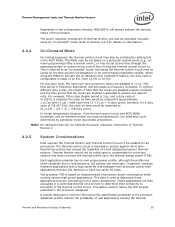
...loop decisions, I /O intensive or have low cache hit rates. In general, compute intensive applications with a high cache hit rate dissipate more processor power than applications that the clocks are interesting from... a thermal solution that exceed the capability of Thermal Monitor 2 4.2.5 System Considerations Intel requires the Thermal Monitor and Thermal Control Circuit to be enabled for details on ...program has its own unique power profile, although the profile has some variability due to activate the on this feature. 4.2.4 On-Demand Mode For testing purposes, the thermal control ...
...loop decisions, I /O intensive or have low cache hit rates. In general, compute intensive applications with a high cache hit rate dissipate more processor power than applications that the clocks are interesting from... a thermal solution that exceed the capability of Thermal Monitor 2 4.2.5 System Considerations Intel requires the Thermal Monitor and Thermal Control Circuit to be enabled for details on ...program has its own unique power profile, although the profile has some variability due to activate the on this feature. 4.2.4 On-Demand Mode For testing purposes, the thermal control ...
Design Guidelines
Page 45
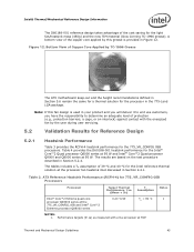
... are based on the test procedure described in the 775-Land LGA package. Figure 12. The tables includes a TA assumption of 39 °C and 40 °C for the 775_VR_CONFIG 05B processors. Table 3. ATX Reference Heatsink Performance (RCFH-4) for the Intel® Core™2 Quad processor Q6000 series at 95 W and Intel® Core™2 Quad processor Q9000 and Q8000 series...
... are based on the test procedure described in the 775-Land LGA package. Figure 12. The tables includes a TA assumption of 39 °C and 40 °C for the 775_VR_CONFIG 05B processors. Table 3. ATX Reference Heatsink Performance (RCFH-4) for the Intel® Core™2 Quad processor Q6000 series at 95 W and Intel® Core™2 Quad processor Q9000 and Q8000 series...

Design Guidelines
Page 47
... altitude. 5.2.4 Reference Heatsink Thermal Validation The Intel reference heatsink was validated within the specific boundary conditions based on the methodology described Section 5.3 , and using a thermal test vehicle. Refer to Chapter 6 for the processor is used for testing complies with the ATX specification which allows an obstruction as low as 76.2 mm above the motherboard (refer...
... altitude. 5.2.4 Reference Heatsink Thermal Validation The Intel reference heatsink was validated within the specific boundary conditions based on the methodology described Section 5.3 , and using a thermal test vehicle. Refer to Chapter 6 for the processor is used for testing complies with the ATX specification which allows an obstruction as low as 76.2 mm above the motherboard (refer...