
Product Guide
Page 1
Intel® Server Board S815EBM1 Product Guide A Guide for Technically Qualified Assemblers of Intel® Identified Subassemblies/Products Order Number: A67054-003 1
Intel® Server Board S815EBM1 Product Guide A Guide for Technically Qualified Assemblers of Intel® Identified Subassemblies/Products Order Number: A67054-003 1
Product Guide
Page 3
... ...7 Back Panel Connectors 8 Front Panel Connectors 9 Server Board Connector and Component Locations 10 Processors ...11 Memory ...11 Intel® 82815E Graphics Memory Controller Hub (GMCH 12 Intel® 82801BA I/O Controller Hub (ICH2 13 Firmware Hub (FWH 13 Input/Output (I/O) Controller 13 Real-Time Clock......20 DIMM Installation Guidelines 20 Installing DIMMs ...20 Removing DIMMs ...21 Installing the I/O Shield...22 Installing the Server Board 23 Installing a Processor ...24 Removing the Processor ...26 Installing a 1 GHz Processor Heatsink 27 Removing the 1 GHz Processor 30 iii
... ...7 Back Panel Connectors 8 Front Panel Connectors 9 Server Board Connector and Component Locations 10 Processors ...11 Memory ...11 Intel® 82815E Graphics Memory Controller Hub (GMCH 12 Intel® 82801BA I/O Controller Hub (ICH2 13 Firmware Hub (FWH 13 Input/Output (I/O) Controller 13 Real-Time Clock......20 DIMM Installation Guidelines 20 Installing DIMMs ...20 Removing DIMMs ...21 Installing the I/O Shield...22 Installing the Server Board 23 Installing a Processor ...24 Removing the Processor ...26 Installing a 1 GHz Processor Heatsink 27 Removing the 1 GHz Processor 30 iii
Product Guide
Page 4
... Setting the BIOS Configuration Jumper 35 Clearing the Passwords...36 3 Configuration Software and Utilities Updating the BIOS with the Intel® Express BIOS Update Utility 37 Updating the BIOS with the Intel® Flash Memory Update Utility 37 Preparing for the Update 37 Obtaining the BIOS Update File 38 Recording the Current... 60 Removable Devices Submenu 60 ATAPI CDROM Drives Submenu 61 Exit Menu ...62 4 Solving BIOS Problems BIOS Beep Codes ...63 BIOS Error Messages ...64 iv Intel Server Board S815EBM1 Product Guide
... Setting the BIOS Configuration Jumper 35 Clearing the Passwords...36 3 Configuration Software and Utilities Updating the BIOS with the Intel® Express BIOS Update Utility 37 Updating the BIOS with the Intel® Flash Memory Update Utility 37 Preparing for the Update 37 Obtaining the BIOS Update File 38 Recording the Current... 60 Removable Devices Submenu 60 ATAPI CDROM Drives Submenu 61 Exit Menu ...62 4 Solving BIOS Problems BIOS Beep Codes ...63 BIOS Error Messages ...64 iv Intel Server Board S815EBM1 Product Guide

Product Guide
Page 5
Server Board Components 10 4. I /O Map ...71 Interrupts ...72 6 Regulatory and Integration Information Product Regulatory Compliance 73 Product Safety Compliance 73 Product EMC Compliance 73 Product ... Heatsink Clips to the Processor Fan Connector ...29 16. Removing the Battery 33 18. 5 Technical Reference Server Board Connectors 67 Baseboard Connectors 68 Power and Hardware Control Connectors 68 Add-In Board and Peripheral Interface Connectors 69 Server Board Resources ...70 Memory Map ...70 DMA Channels ...70 I /O Shield Dimensions 22 6. Back Panel Connectors 8 2. ...
Server Board Components 10 4. I /O Map ...71 Interrupts ...72 6 Regulatory and Integration Information Product Regulatory Compliance 73 Product Safety Compliance 73 Product EMC Compliance 73 Product ... Heatsink Clips to the Processor Fan Connector ...29 16. Removing the Battery 33 18. 5 Technical Reference Server Board Connectors 67 Baseboard Connectors 68 Power and Hardware Control Connectors 68 Add-In Board and Peripheral Interface Connectors 69 Server Board Resources ...70 Memory Map ...70 DMA Channels ...70 I /O Shield Dimensions 22 6. Back Panel Connectors 8 2. ...
Product Guide
Page 6
... Submenu 54 19. ACPI Submenu ...57 23. Boot Device Priority Submenu 59 25. BIOS Error Messages 64 31. DMA Channels...70 33. Interrupts ...72 vi Intel Server Board S815EBM1 Product Guide Power and Hardware Control Connectors 68 22. Processor and Memory Module Combinations 12 4. Security Menu...55 20. Removable Devices Submenu 60 27. Exit... Program Modes 35 6. BIOS Setup Program Function Keys 43 8. ATAPI CDROM Drives Submenu 61 28. Advanced Menu ...46 12. Hard Disk Drives Submenu 60 26. Server Board Features 7 2. IDE Configuration Submenu 50 16.
... Submenu 54 19. ACPI Submenu ...57 23. Boot Device Priority Submenu 59 25. BIOS Error Messages 64 31. DMA Channels...70 33. Interrupts ...72 vi Intel Server Board S815EBM1 Product Guide Power and Hardware Control Connectors 68 22. Processor and Memory Module Combinations 12 4. Security Menu...55 20. Removable Devices Submenu 60 27. Exit... Program Modes 35 6. BIOS Setup Program Function Keys 43 8. ATAPI CDROM Drives Submenu 61 28. Advanced Menu ...46 12. Hard Disk Drives Submenu 60 26. Server Board Features 7 2. IDE Configuration Submenu 50 16.
Product Guide
Page 7
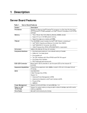
... memory • Support for single row or double row DIMMs The S815EBM1 board includes the Intel® 815E Chipset, consisting of: • Intel® 82815 Graphics and Memory Controller Hub (GMCH) • Intel® 82801BA I/O Controller Hub (ICH2) • 4 Mbit Firmware Hub (FWH) (STM M50FW040 or equivalent) SMSC LPC47M132 LPC bus I /O controller. 1 Description Server Board Features Table 1.
... memory • Support for single row or double row DIMMs The S815EBM1 board includes the Intel® 815E Chipset, consisting of: • Intel® 82815 Graphics and Memory Controller Hub (GMCH) • Intel® 82801BA I/O Controller Hub (ICH2) • 4 Mbit Firmware Hub (FWH) (STM M50FW040 or equivalent) SMSC LPC47M132 LPC bus I /O controller. 1 Description Server Board Features Table 1.
Product Guide
Page 8
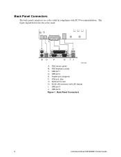
The figure legend below lists the colors used. PS/2 keyboard, purple C. Parallel port, burgundy F. Back Panel Connectors 8 Intel Server Board S815EBM1 Product Guide Back Panel Connectors The back panel connectors are color-coded in compliance with LED display I. A E H C BD F G IJ OM12208 A. USB port 1 D. PS/2 mouse, green B. USB port 3 E. USB port 0 J. RJ-45 LAN connector with PC 99 recommendations. Serial port A, teal H. VGA port, blue G. USB port 2 Figure 1.
The figure legend below lists the colors used. PS/2 keyboard, purple C. Parallel port, burgundy F. Back Panel Connectors 8 Intel Server Board S815EBM1 Product Guide Back Panel Connectors The back panel connectors are color-coded in compliance with LED display I. A E H C BD F G IJ OM12208 A. USB port 1 D. PS/2 mouse, green B. USB port 3 E. USB port 0 J. RJ-45 LAN connector with PC 99 recommendations. Serial port A, teal H. VGA port, blue G. USB port 2 Figure 1.
Product Guide
Page 11
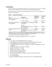
...1 GHz Pentium III is dependent upon package type. S815EBM1 Fan Heatsink (FHS) only supports FCPGA2 packaging type - The processor connects to the Intel server board web site at this speed by product s-spec. Memory The board supports 168-pin SDRAM DIMMs as defined below: &#...with gold-plated contacts • Three DIMM slots are not included with the server board and must be purchased separately. customers can determine S815EBM1 support at : http://support.intel.com/support/motherboards/server/S815EBM1/ For instructions on processor support for flexible memory configurations • 133 MHz...
...1 GHz Pentium III is dependent upon package type. S815EBM1 Fan Heatsink (FHS) only supports FCPGA2 packaging type - The processor connects to the Intel server board web site at this speed by product s-spec. Memory The board supports 168-pin SDRAM DIMMs as defined below: &#...with gold-plated contacts • Three DIMM slots are not included with the server board and must be purchased separately. customers can determine S815EBM1 support at : http://support.intel.com/support/motherboards/server/S815EBM1/ For instructions on processor support for flexible memory configurations • 133 MHz...
Product Guide
Page 12
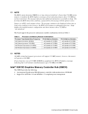
... detection. If more than four rows of SDRAM. • Support for ACPI Rev 2.0 and APM Rev 1.2 compliant power management. 12 Intel Server Board S815EBM1 Product Guide Setup displays the installed memory configuration and shows memory above 512 MB has not been initialized. ✏ NOTE The BIOS cannot... determine DIMM size or type when not initialized. Intel® 82815E Graphics Memory Controller Hub (GMCH) The GMCH provides the following: • An integrated Synchronous DRAM memory controller with the ...
... detection. If more than four rows of SDRAM. • Support for ACPI Rev 2.0 and APM Rev 1.2 compliant power management. 12 Intel Server Board S815EBM1 Product Guide Setup displays the installed memory configuration and shows memory above 512 MB has not been initialized. ✏ NOTE The BIOS cannot... determine DIMM size or type when not initialized. Intel® 82815E Graphics Memory Controller Hub (GMCH) The GMCH provides the following: • An integrated Synchronous DRAM memory controller with the ...
Product Guide
Page 13
... 256-byte battery backed CMOS RAM). • Supports two Master/DMA devices. USB Support The server board has four rear panel USB ports. Description 13 You can connect four USB peripheral devices directly to be compatible with UHCI. Intel® 82801BA I /O controller features the following: • One parallel port with Extended Capabilities Port...
... 256-byte battery backed CMOS RAM). • Supports two Master/DMA devices. USB Support The server board has four rear panel USB ports. Description 13 You can connect four USB peripheral devices directly to be compatible with UHCI. Intel® 82801BA I /O controller features the following: • One parallel port with Extended Capabilities Port...

Product Guide
Page 14
... (LS-120) drives Expansion Slots The S815EBM1 board has three add-in board connectors. You do not need to view and change all Setup options. Security Passwords The BIOS includes security features that meets the requirements for your server. The interface supports: • Up to Setup. 14 Intel Server Board S815EBM1 Product Guide BIOS The BIOS provides the...
... (LS-120) drives Expansion Slots The S815EBM1 board has three add-in board connectors. You do not need to view and change all Setup options. Security Passwords The BIOS includes security features that meets the requirements for your server. The interface supports: • Up to Setup. 14 Intel Server Board S815EBM1 Product Guide BIOS The BIOS provides the...
Product Guide
Page 15
...host memory that copies data directly to the back panel RJ-45 connector with the Intel 82801BA ICH2) provides a Fast Ethernet Wired for viewing and changing depending on the server board. Setup options are then available for Management (WfM) PCI LAN subsystem providing both 10Base...the supervisor password or the user password to boot the server. Features include: • 32-bit, 33-MHz direct bus mastering on Intel's support web site at: http://support.intel.com/support/motherboards/server/S815EBM1/ Description 15 The Intel 82562ET provides the following functions: • Basic 10/100...
...host memory that copies data directly to the back panel RJ-45 connector with the Intel 82801BA ICH2) provides a Fast Ethernet Wired for viewing and changing depending on the server board. Setup options are then available for Management (WfM) PCI LAN subsystem providing both 10Base...the supervisor password or the user password to boot the server. Features include: • 32-bit, 33-MHz direct bus mastering on Intel's support web site at: http://support.intel.com/support/motherboards/server/S815EBM1/ Description 15 The Intel 82562ET provides the following functions: • Basic 10/100...
Product Guide
Page 16
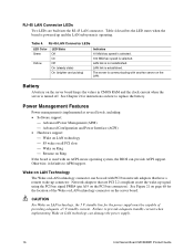
... instructions on how to provide adequate standby current when implementing Wake on LAN technology can damage the power supply. 16 Intel Server Board S815EBM1 Product Guide Wake on LAN Technology The Wake on LAN technology connector can provide ACPI support. Table 4. Power Management Features... standby line for the location of providing adequate +5 V standby current. The server is communicating with another server on the server board keeps the values in CMOS RAM and the clock current when the server is used with an ACPI-aware operating system, the BIOS can be capable of...
... instructions on how to provide adequate standby current when implementing Wake on LAN technology can damage the power supply. 16 Intel Server Board S815EBM1 Product Guide Wake on LAN Technology The Wake on LAN technology connector can provide ACPI support. Table 4. Power Management Features... standby line for the location of providing adequate +5 V standby current. The server is communicating with another server on the server board keeps the values in CMOS RAM and the clock current when the server is used with an ACPI-aware operating system, the BIOS can be capable of...
Product Guide
Page 17
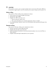
...; The second call enables access (when the appropriate software is loaded). • For external modems, hardware on the server board monitors the ring indicate (RI) input of Resume on Ring can be summarized as follows: • Resumes operation from the APM sleep mode. • ...Requires only one call to support multiple wake events from the PCI and/or USB buses exceeds power supply capacity, the server board may lose register settings stored in memory, etc. Resume on Ring can be unmasked for external and internal modems; Description 17 Wake on Ring The...
...; The second call enables access (when the appropriate software is loaded). • For external modems, hardware on the server board monitors the ring indicate (RI) input of Resume on Ring can be summarized as follows: • Resumes operation from the APM sleep mode. • ...Requires only one call to support multiple wake events from the PCI and/or USB buses exceeds power supply capacity, the server board may lose register settings stored in memory, etc. Resume on Ring can be unmasked for external and internal modems; Description 17 Wake on Ring The...
Product Guide
Page 19
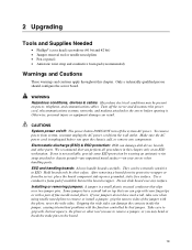
...chassis, add, or remove any components. Take care to the server before you must unplug the AC power cord from the server, place the board component side up on /off: The power button DOES NOT turn off the server and disconnect the power cord, telecommunications systems, networks, and ...such a tab, take care when using needle nosed pliers to chassis groundany surface. Only a technically qualified person should configure the server board. If one is unplugged before opening it. Make sure the AC power cord is not available, provide some ESD protection by wearing an ...
...chassis, add, or remove any components. Take care to the server before you must unplug the AC power cord from the server, place the board component side up on /off: The power button DOES NOT turn off the server and disconnect the power cord, telecommunications systems, networks, and ...such a tab, take care when using needle nosed pliers to chassis groundany surface. Only a technically qualified person should configure the server board. If one is unplugged before opening it. Make sure the AC power cord is not available, provide some ESD protection by wearing an ...

Product Guide
Page 20
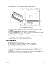
...DIMM Specification • PC Registered DIMM Specification You can access the PC Serial Presence Detect Specification at: http://www.intel.com/design/chipsets/memory/ The boards have three 168-pin DIMM sockets arranged as banks 0, 1, and 2 as shown in the Main Memory section ... http://www.intel.com/design/chipsets/memory/ Installing DIMMs To install DIMMs, follow these documents through the Internet at the beginning of this chapter. 2. The memory module requirements are listed in Figure 4. Turn off the server and disconnect the AC power cord. 20 Intel Server Board S815EBM1 Product Guide...
...DIMM Specification • PC Registered DIMM Specification You can access the PC Serial Presence Detect Specification at: http://www.intel.com/design/chipsets/memory/ The boards have three 168-pin DIMM sockets arranged as banks 0, 1, and 2 as shown in the Main Memory section ... http://www.intel.com/design/chipsets/memory/ Installing DIMMs To install DIMMs, follow these documents through the Internet at the beginning of this chapter. 2. The memory module requirements are listed in Figure 4. Turn off the server and disconnect the AC power cord. 20 Intel Server Board S815EBM1 Product Guide...
Product Guide
Page 21
... notches in the bottom edge of the DIMM with the keys in Figure 4). 7. Reinstall and reconnect any parts you removed or disconnected to the server. Remove the server's cover and locate the DIMM sockets (see inset in the socket (see Figure 4). 0 1 2 OM12202 Figure 4. Make sure the clips at each .... Hold the DIMM by the edges, remove it in place. 9. Make sure the clips are pushed outward to the open position. 5. Replace the server's cover and reconnect the AC power cord. Insert the bottom edge of the DIMM socket(s) are firmly in an anti-static package. 7. Removing DIMMs ...
... notches in the bottom edge of the DIMM with the keys in Figure 4). 7. Reinstall and reconnect any parts you removed or disconnected to the server. Remove the server's cover and locate the DIMM sockets (see inset in the socket (see Figure 4). 0 1 2 OM12202 Figure 4. Make sure the clips at each .... Hold the DIMM by the edges, remove it in place. 9. Make sure the clips are pushed outward to the open position. 5. Replace the server's cover and reconnect the AC power cord. Insert the bottom edge of the DIMM socket(s) are firmly in an anti-static package. 7. Removing DIMMs ...

Product Guide
Page 22
...transmissions, protects internal components from the chassis supplier. Installing the I/O Shield CAUTION Systems based on these boards need the I/O shield properly installed to pass emissions (EMI) certification testing and to meet Class B regulatory ... the chassis. The boxed server board comes with an improperly installed I /O shield from the chassis vendor. If installing this board in the chassis. Install the I/O shield before installing the server board in an 1U chassis, ... Without the I/O shield, or with an I /O Shield Dimensions OM12390 22 Intel Server Board S815EBM1 Product Guide
...transmissions, protects internal components from the chassis supplier. Installing the I/O Shield CAUTION Systems based on these boards need the I/O shield properly installed to pass emissions (EMI) certification testing and to meet Class B regulatory ... the chassis. The boxed server board comes with an improperly installed I /O shield from the chassis vendor. If installing this board in the chassis. Install the I/O shield before installing the server board in an 1U chassis, ... Without the I/O shield, or with an I /O Shield Dimensions OM12390 22 Intel Server Board S815EBM1 Product Guide

Product Guide
Page 23
... procedures described here. Disconnect the server from its power source before you open the server can result in personal injury or equipment damage. WARNING Only qualified technical personnel should attempt this procedure. OM12203 Figure 6. Installing the Server Board Refer to your chassis manual for... regulatory requirements and installation instructions and precautions. Refer to Page 73 for instructions on installing the server board. Failure to the chassis. Location of the mounting screw holes. ✏ NOTES You will need a Phillips (#2 bit) ...
... procedures described here. Disconnect the server from its power source before you open the server can result in personal injury or equipment damage. WARNING Only qualified technical personnel should attempt this procedure. OM12203 Figure 6. Installing the Server Board Refer to your chassis manual for... regulatory requirements and installation instructions and precautions. Refer to Page 73 for instructions on installing the server board. Failure to the chassis. Location of the mounting screw holes. ✏ NOTES You will need a Phillips (#2 bit) ...
Product Guide
Page 24
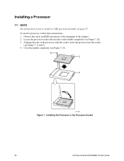
... socket and raise the socket handle completely (see Figure 7, D). Close the handle completely (see Figure 7, B). 3. B C A D OM11065 Figure 7. Installing the Processor in the Processor Socket 24 Intel Server Board S815EBM1 Product Guide Observe the safety and ESD precautions at the beginning of the processor with the socket, insert the processor into the socket (see page...
... socket and raise the socket handle completely (see Figure 7, D). Close the handle completely (see Figure 7, B). 3. B C A D OM11065 Figure 7. Installing the Processor in the Processor Socket 24 Intel Server Board S815EBM1 Product Guide Observe the safety and ESD precautions at the beginning of the processor with the socket, insert the processor into the socket (see page...


