
User Guide
Page 2
...personal injury or death may occur. Intel's own chassis are trademarks or registered trademarks of Intel Corporation or its subsidiaries in the United States and other application in which the failure of airflow required for cooling. Intel server boards contain a number of high-density... for any patent, copyright or other intellectual property right. All Rights Reserved ii Intel® Server System SC5400RA User's Guide Intel may be held responsible if components fail or the server board does not operate correctly when used together. No license, express or implied,...
...personal injury or death may occur. Intel's own chassis are trademarks or registered trademarks of Intel Corporation or its subsidiaries in the United States and other application in which the failure of airflow required for cooling. Intel server boards contain a number of high-density... for any patent, copyright or other intellectual property right. All Rights Reserved ii Intel® Server System SC5400RA User's Guide Intel may be held responsible if components fail or the server board does not operate correctly when used together. No license, express or implied,...

User Guide
Page 3
... und Servergehäusen auf der Intel® Server Deployment Toolkit 2.0 CD oder unter http://support.intel.com/support/motherboards/server/sb/cs-010770.htm. Vea Intel Server Boards and Server Chassis Safety Information en el Intel® Server Deployment Toolkit 2.0 CD y/o en http:// support.intel.com/support/motherboards/server/sb/cs-010770.htm. Intel® Server System SC5400RA User's Guide iii Instrucciones de seguridad importantes...
... und Servergehäusen auf der Intel® Server Deployment Toolkit 2.0 CD oder unter http://support.intel.com/support/motherboards/server/sb/cs-010770.htm. Vea Intel Server Boards and Server Chassis Safety Information en el Intel® Server Deployment Toolkit 2.0 CD y/o en http:// support.intel.com/support/motherboards/server/sb/cs-010770.htm. Intel® Server System SC5400RA User's Guide iii Instrucciones de seguridad importantes...
User Guide
Page 4
... surface on /off: The power button DOES NOT turn off the server and disconnect the power cord, telecommunications systems, networks, and modems attached to the server before you are using this guide to ensure and maintain compliance with ...server product, whether you open the chassis, add, or remove any surface. To remove power from system, you perform all procedures in this guide. Use a conductive foam pad if available but not the board wrapper. Turn off the system AC power. We recommend that you must adhere to ESD. They can result. iv Intel® Server System SC5400RA...
... surface on /off: The power button DOES NOT turn off the server and disconnect the power cord, telecommunications systems, networks, and modems attached to the server before you are using this guide to ensure and maintain compliance with ...server product, whether you open the chassis, add, or remove any surface. To remove power from system, you perform all procedures in this guide. Use a conductive foam pad if available but not the board wrapper. Turn off the system AC power. We recommend that you must adhere to ESD. They can result. iv Intel® Server System SC5400RA...

User Guide
Page 8
... the server system product box • One Intel® Server System SC5400RA Quick Start User's Guide, in the server system hardware box • One USB cable, installed in the server system • One IDE cable, in the hardware box • One COM2 cable, in the hardware box • Four 24-inch and two 34-inch SATA cables, in the chassis •...
... the server system product box • One Intel® Server System SC5400RA Quick Start User's Guide, in the server system hardware box • One USB cable, installed in the server system • One IDE cable, in the hardware box • One COM2 cable, in the hardware box • Four 24-inch and two 34-inch SATA cables, in the chassis •...

User Guide
Page 11
... ...19 Chapter 2: Hardware Installations and Upgrades 23 Before You Begin ...23 Tools and Supplies Needed 23 System References 23 Removing and Installing the Chassis Cover 24 Removing the Chassis Cover 24 Installing the Chassis Cover 25 Removing and Installing the Front Bezel 26 Removing the Bezel Assembly (Pedestal Only 26 Intel® Server System SC5400RA User's Guide xi
... ...19 Chapter 2: Hardware Installations and Upgrades 23 Before You Begin ...23 Tools and Supplies Needed 23 System References 23 Removing and Installing the Chassis Cover 24 Removing the Chassis Cover 24 Installing the Chassis Cover 25 Removing and Installing the Front Bezel 26 Removing the Bezel Assembly (Pedestal Only 26 Intel® Server System SC5400RA User's Guide xi

User Guide
Page 17
... Swap Cage 41 Figure 41. Removing Hard Drive from Drive Cage 43 Intel® Server System SC5400RA User's Guide xvii Configuration Jumpers 14 Figure 10. Removing Drive Carrier from Drive Cage 34 Figure 29. Server System Back 8 Figure 6. Attaching Device Slides to Drive Carrier 39 Figure 36...Hard Drive to Hard Drive 30 Figure 21. Installing the Chassis Cover 25 Figure 14. Opening Lower Door of Fixed Drive Cage 29 Figure 19. Inserting Drive Carrier into Drive Cage 35 Figure 30. Intel® Server System SC5400RA 1 Figure 2. Removing Six-drive Fixed Drive Cage 28 ...
... Swap Cage 41 Figure 41. Removing Hard Drive from Drive Cage 43 Intel® Server System SC5400RA User's Guide xvii Configuration Jumpers 14 Figure 10. Removing Drive Carrier from Drive Cage 34 Figure 29. Server System Back 8 Figure 6. Attaching Device Slides to Drive Carrier 39 Figure 36...Hard Drive to Hard Drive 30 Figure 21. Installing the Chassis Cover 25 Figure 14. Opening Lower Door of Fixed Drive Cage 29 Figure 19. Inserting Drive Carrier into Drive Cage 35 Figure 30. Intel® Server System SC5400RA 1 Figure 2. Removing Six-drive Fixed Drive Cage 28 ...

User Guide
Page 25
... Management support Description Two fixed, non-redundant chassis fans: • One 120-mm fan ...port B connector • Two RJ45 NIC connectors for 10/100/1000 Mb connections: Dual GbE with Intel® I/O Acceleration Technology • Four USB 2.0 ports at the...Intel® Local Control Panel (optional component sold separately) • Support for the Intel® Remote Management Module (optional component sold separately) • Support for Intel® System Management software • Intel® Light-Guided Diagnostics on field replaceable units Intel® Server System SC5400RA...
... Management support Description Two fixed, non-redundant chassis fans: • One 120-mm fan ...port B connector • Two RJ45 NIC connectors for 10/100/1000 Mb connections: Dual GbE with Intel® I/O Acceleration Technology • Four USB 2.0 ports at the...Intel® Local Control Panel (optional component sold separately) • Support for the Intel® Remote Management Module (optional component sold separately) • Support for Intel® System Management software • Intel® Light-Guided Diagnostics on field replaceable units Intel® Server System SC5400RA...

User Guide
Page 34
.... Enclosure management SATA SGPIO header BB. Serial B / emergency management port header OO. J. Front control panel header MM. Server Board Connector and Component Locations 12 Intel® Server System SC5400RA User's Guide Diagnostic and Identify LEDs (see Figure 6 on page 9) L. Chassis intrusion header Figure 8. Processor power connector Y. SATA_Key: SATA RAID 5 key connector NN. RMM connector (connector for...
.... Enclosure management SATA SGPIO header BB. Serial B / emergency management port header OO. J. Front control panel header MM. Server Board Connector and Component Locations 12 Intel® Server System SC5400RA User's Guide Diagnostic and Identify LEDs (see Figure 6 on page 9) L. Chassis intrusion header Figure 8. Processor power connector Y. SATA_Key: SATA RAID 5 key connector NN. RMM connector (connector for...
User Guide
Page 46
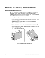
... the following figure. 5. Removing the Chassis Cover AF000555 24 Intel® Server System SC5400RA User's Guide Before removing the top cover, power down the server and unplug all peripheral devices connected to the server. B A B A Figure 12. Removing and Installing the Chassis Cover Removing the Chassis Cover The Intel® Server System SC5400RA must be needed to prevent the system from sliding on page iii. 2.
... the following figure. 5. Removing the Chassis Cover AF000555 24 Intel® Server System SC5400RA User's Guide Before removing the top cover, power down the server and unplug all peripheral devices connected to the server. B A B A Figure 12. Removing and Installing the Chassis Cover Removing the Chassis Cover The Intel® Server System SC5400RA must be needed to prevent the system from sliding on page iii. 2.
User Guide
Page 47
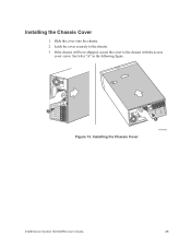
If the chassis will be re-shipped, secure the cover to the chassis. 3. Installing the Chassis Cover 1. Slide the cover onto the chassis. 2. Installing the Chassis Cover AF000572 Intel® Server System SC5400RA User's Guide 25 See letter "A" in the following figure. A A Figure 13. Latch the cover securely to the chassis with the access cover screw.
If the chassis will be re-shipped, secure the cover to the chassis. 3. Installing the Chassis Cover 1. Slide the cover onto the chassis. 2. Installing the Chassis Cover AF000572 Intel® Server System SC5400RA User's Guide 25 See letter "A" in the following figure. A A Figure 13. Latch the cover securely to the chassis with the access cover screw.
User Guide
Page 48
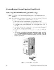
... and the AC power cable. 3. See letter "A" in the figure. 6. Removing the Front Bezel 26 Intel® Server System SC5400RA User's Guide Rotate the bezel assembly no more than 40 degrees outward. See letter "C". For instructions, see "Removing the Chassis Cover" on the left -hand side of the bezel assembly to the back of the...
... and the AC power cable. 3. See letter "A" in the figure. 6. Removing the Front Bezel 26 Intel® Server System SC5400RA User's Guide Rotate the bezel assembly no more than 40 degrees outward. See letter "C". For instructions, see "Removing the Chassis Cover" on the left -hand side of the bezel assembly to the back of the...
User Guide
Page 49
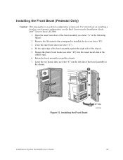
... (see letter "C"). 4. Installing the Front Bezel 40° Max AF001505 Intel® Server System SC5400RA User's Guide 27 Close the outer bezel door (see letter "D") into the raised metal slots at the chassis edge. 6. For instructions on the left side of the bezel assembly to the chassis. Remove the filler panels that correspond to a pedestal configuration...
... (see letter "C"). 4. Installing the Front Bezel 40° Max AF001505 Intel® Server System SC5400RA User's Guide 27 Close the outer bezel door (see letter "D") into the raised metal slots at the chassis edge. 6. For instructions on the left side of the bezel assembly to the chassis. Remove the filler panels that correspond to a pedestal configuration...
User Guide
Page 50
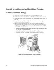
Remove the chassis cover. Power down the server and unplug all peripheral devices and the AC power cable. 3. For instructions, see "Removing and Installing the Front Bezel" on page 24. 4. Push the blue ... installed. Remove the front bezel if it easier to release the fixed drive cage. For instructions, see "Removing the Chassis Cover" on page 26. 5. Removing Six-drive Fixed Drive Cage 28 Intel® Server System SC5400RA User's Guide Position the drive bay horizontally before opening the drive cage doors. Installing and Removing Fixed Hard Drive...
Remove the chassis cover. Power down the server and unplug all peripheral devices and the AC power cable. 3. For instructions, see "Removing and Installing the Front Bezel" on page 24. 4. Push the blue ... installed. Remove the front bezel if it easier to release the fixed drive cage. For instructions, see "Removing the Chassis Cover" on page 26. 5. Removing Six-drive Fixed Drive Cage 28 Intel® Server System SC5400RA User's Guide Position the drive bay horizontally before opening the drive cage doors. Installing and Removing Fixed Hard Drive...
User Guide
Page 54
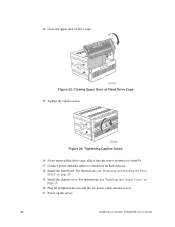
...captive screw. AF000586 Figure 24. Power up the server. 32 Intel® Server System SC5400RA User's Guide AF000585 Figure 23. Install the front bezel. Plug all peripheral devices and the AC power cable into the server system to connectors on page 25. 20. Closing ...Upper Door of drive cage. Close the upper door of Fixed Drive Cage 15. Install the chassis...
...captive screw. AF000586 Figure 24. Power up the server. 32 Intel® Server System SC5400RA User's Guide AF000585 Figure 23. Install the front bezel. Plug all peripheral devices and the AC power cable into the server system to connectors on page 25. 20. Closing ...Upper Door of drive cage. Close the upper door of Fixed Drive Cage 15. Install the chassis...
User Guide
Page 69
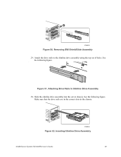
Attach the drive rails to Slimline Drive Assembly 30. Inserting Slimline Drive Assembly Intel® Server System SC5400RA User's Guide 47 A AF000633 Figure 52. Slide the slimline drive assembly into the server chassis. See the following figure. Removing EMI Shield/Slide Assembly 29. A Figure 51. Make sure that the drive rails are in the correct slots in the chassis. Attaching Drive Rails to the slimline drive assembly using the top set of holes. See the following figure. A A AF000634 Figure 50.
Attach the drive rails to Slimline Drive Assembly 30. Inserting Slimline Drive Assembly Intel® Server System SC5400RA User's Guide 47 A AF000633 Figure 52. Slide the slimline drive assembly into the server chassis. See the following figure. Removing EMI Shield/Slide Assembly 29. A Figure 51. Make sure that the drive rails are in the correct slots in the chassis. Attaching Drive Rails to the slimline drive assembly using the top set of holes. See the following figure. A A AF000634 Figure 50.
User Guide
Page 124
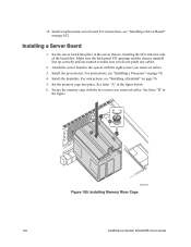
... cage into place in the server chassis, inserting the I /O openings and the chassis standoff line up correctly and use caution to the system with the two screws you removed earlier. 18. Install a replacement server board. B A AF001410 Figure 109. Installing Memory Riser Cage 102 Intel® Server System SC5400RA User's Guide For instructions, see "Installing a Server Board" on page 70. 4. See...
... cage into place in the server chassis, inserting the I /O openings and the chassis standoff line up correctly and use caution to the system with the two screws you removed earlier. 18. Install a replacement server board. B A AF001410 Figure 109. Installing Memory Riser Cage 102 Intel® Server System SC5400RA User's Guide For instructions, see "Installing a Server Board" on page 70. 4. See...
User Guide
Page 151
...used throughout the documentation and may result in noncompliance with product regulations in the region(s) in which the product is ignored. Your server should be marked on the website for a particular product, the product documentation takes precedence. Indicates shock hazards that may cause .... In the event of bodily injury, electrical shock, fire, and equipment damage, read , observe, and adhere to Intel® server boards, Intel® server chassis (pedestal and rackmount) and installed peripherals. Use only the described, regulated components specified in this guide.
...used throughout the documentation and may result in noncompliance with product regulations in the region(s) in which the product is ignored. Your server should be marked on the website for a particular product, the product documentation takes precedence. Indicates shock hazards that may cause .... In the event of bodily injury, electrical shock, fire, and equipment damage, read , observe, and adhere to Intel® server boards, Intel® server chassis (pedestal and rackmount) and installed peripherals. Use only the described, regulated components specified in this guide.

User Guide
Page 179
... an ITE application, may require further evaluation. Intel® Server System SC5400RA User's Guide 157 For more information, please contact your end system product may be installed in offices, schools, computer rooms, and similar commercial type locations. The final configuration of your local Intel representative. Product Safety Compliance This server chassis product, when correctly integrated per this guide...
... an ITE application, may require further evaluation. Intel® Server System SC5400RA User's Guide 157 For more information, please contact your end system product may be installed in offices, schools, computer rooms, and similar commercial type locations. The final configuration of your local Intel representative. Product Safety Compliance This server chassis product, when correctly integrated per this guide...
User Guide
Page 180
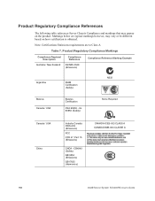
... (Emissions) GB17625 (Harmonics) CANADA ICES-003 CLASS A CANADA NMB-003 CLASSE A 158 Intel® Server System SC5400RA User's Guide Note: Certifications Emissions requirements are typical markings however, may appear on how certification is obtained. Product Regulatory Compliance References The following table references Server Chassis Compliance and markings that may vary or be different based on the...
... (Emissions) GB17625 (Harmonics) CANADA ICES-003 CLASS A CANADA NMB-003 CLASSE A 158 Intel® Server System SC5400RA User's Guide Note: Certifications Emissions requirements are typical markings however, may appear on how certification is obtained. Product Regulatory Compliance References The following table references Server Chassis Compliance and markings that may vary or be different based on the...
User Guide
Page 189
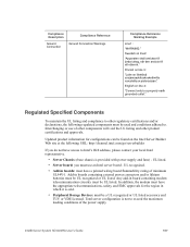
...provided with power supply and fans) - Intel® Server System SC5400RA User's Guide 167 Finnish on line 3: "Laite on line2: "Apparaten skall anslutas till jordat uttag, när den ansluts till ett nätverk." Interchanging or use an Intel server board - In addition, the modem must...can be found on line 4: "Connect only to Intel's Web address, please contact your local Intel representative. • Server Chassis: (base chassis is sold. • Peripheral Storage Devices: must be UL recognized or UL listed. Total server configuration is not to . Add-in board containing ...
...provided with power supply and fans) - Intel® Server System SC5400RA User's Guide 167 Finnish on line 3: "Laite on line2: "Apparaten skall anslutas till jordat uttag, när den ansluts till ett nätverk." Interchanging or use an Intel server board - In addition, the modem must...can be found on line 4: "Connect only to Intel's Web address, please contact your local Intel representative. • Server Chassis: (base chassis is sold. • Peripheral Storage Devices: must be UL recognized or UL listed. Total server configuration is not to . Add-in board containing ...

