
User Guide
Page 12
... 63 Removing a PCI Add-in Card 64 Installing the I/O Expansion Module(s 66 Removing the I/O Expansion Module(s 67 Installing the Intel® RMM and Intel® RMM NIC 68 Removing the Intel® RMM and Intel® RMM NIC 70 Replacing the Mid-plane Board 71 Removing the Mid-plane Board 71 xii Intel® Server System SR2500AL User...
... 63 Removing a PCI Add-in Card 64 Installing the I/O Expansion Module(s 66 Removing the I/O Expansion Module(s 67 Installing the Intel® RMM and Intel® RMM NIC 68 Removing the Intel® RMM and Intel® RMM NIC 70 Replacing the Mid-plane Board 71 Removing the Mid-plane Board 71 xii Intel® Server System SR2500AL User...

User Guide
Page 14
... Light Does Not Light 116 CD-ROM Drive or DVD-ROM Drive Activity Light Does Not Light 116 Cannot Connect to a Server 116 Problems with Network 117 System Boots when Installing PCI Card 118 Problems with Newly Installed Application Software 118 Problems with Application Software that Ran Correctly Earlier 118 Devices are not... Europe (CE Declaration of Conformity 142 VCCI (Japan) ...142 BSMI (Taiwan) ...142 Korean Compliance (RRL 143 CNCA (CCC-China 143 Product Ecology Compliance 143 xiv Intel® Server System SR2500AL User's Guide
... Light Does Not Light 116 CD-ROM Drive or DVD-ROM Drive Activity Light Does Not Light 116 Cannot Connect to a Server 116 Problems with Network 117 System Boots when Installing PCI Card 118 Problems with Newly Installed Application Software 118 Problems with Application Software that Ran Correctly Earlier 118 Devices are not... Europe (CE Declaration of Conformity 142 VCCI (Japan) ...142 BSMI (Taiwan) ...142 Korean Compliance (RRL 143 CNCA (CCC-China 143 Product Ecology Compliance 143 xiv Intel® Server System SR2500AL User's Guide
User Guide
Page 18
... the Carrier 53 Figure 46. Removing the PCI Riser Card from the Server System 71 Figure 62. Removing the Bridge Board from the Server System (Full Height Side 61 Figure 54. Installing the Server Board 81 Figure 72. Removing the Intel® RMM and the Intel® RMM NIC Module from the Server System 87 Figure 76. Installing the RAID...
... the Carrier 53 Figure 46. Removing the PCI Riser Card from the Server System 71 Figure 62. Removing the Bridge Board from the Server System (Full Height Side 61 Figure 54. Installing the Server Board 81 Figure 72. Removing the Intel® RMM and the Intel® RMM NIC Module from the Server System 87 Figure 76. Installing the RAID...

User Guide
Page 26
Intel® Server System SR2500ALLX and/or the Intel® Server System SR2500ALBRP Feature Summary Feature Dimensions Server Board Processor Memory Chipset Peripheral Interfaces I /O Controller Hub External connections: • Stacked PS/2* ports for keyboard and mouse • RJ45 Serial B port • Two RJ45 NIC connectors for 10/100/1000 Mb... slot supporting 1U or 2U PCI-X* and PCI Express* riser cards 4 Intel® Server System SR2500AL User's Guide Table 2 summarizes the features of : • Intel® 5000P Memory Controller Hub (MCH) • Intel® 6321ESB I /O Controll...
Intel® Server System SR2500ALLX and/or the Intel® Server System SR2500ALBRP Feature Summary Feature Dimensions Server Board Processor Memory Chipset Peripheral Interfaces I /O Controller Hub External connections: • Stacked PS/2* ports for keyboard and mouse • RJ45 Serial B port • Two RJ45 NIC connectors for 10/100/1000 Mb... slot supporting 1U or 2U PCI-X* and PCI Express* riser cards 4 Intel® Server System SR2500AL User's Guide Table 2 summarizes the features of : • Intel® 5000P Memory Controller Hub (MCH) • Intel® 6321ESB I /O Controll...

User Guide
Page 27
Table 2. Intel® Server System SR2500ALLX and/or the Intel® Server System SR2500ALBRP Feature Summary Feature Hard Drives Peripherals Control Panel (dependent on option selected) LEDs and displays (dependent on option ...selected) Description • Five hot-swap SATA / SAS drives • Drive bay for sixth hot-swap SATA / SAS drive or a 3.5 inch tape drive • Slimline bay for IDE optical drive • PCI...
Table 2. Intel® Server System SR2500ALLX and/or the Intel® Server System SR2500ALBRP Feature Summary Feature Hard Drives Peripherals Control Panel (dependent on option selected) LEDs and displays (dependent on option ...selected) Description • Five hot-swap SATA / SAS drives • Drive bay for sixth hot-swap SATA / SAS drive or a 3.5 inch tape drive • Slimline bay for IDE optical drive • PCI...
User Guide
Page 43
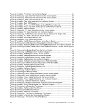
Upper Power Receptacle E. I/O Module (Optional) I OM J HG F E TP02125 A. Video L. PS2* Keyboard and Mouse Connectors Figure 14. Upper Power Supply Module D. Rear of Server System A B C D P N LK I . Lower Power Receptacle F. NIC 2 N. DB-9 Serial A Connector Knockout M. NIC 1 O. Server Management NIC (Optional) H. USB 6 J. Low Profile Add-in Card Slots C. RJ45 Serial B Connector P. Full Height PCI Add-in Card Slots B. USB 5 K. Lower Power Supply Module G. Server System Back Intel® Server System SR2500AL User's Guide 21
Upper Power Receptacle E. I/O Module (Optional) I OM J HG F E TP02125 A. Video L. PS2* Keyboard and Mouse Connectors Figure 14. Upper Power Supply Module D. Rear of Server System A B C D P N LK I . Lower Power Receptacle F. NIC 2 N. DB-9 Serial A Connector Knockout M. NIC 1 O. Server Management NIC (Optional) H. USB 6 J. Low Profile Add-in Card Slots C. RJ45 Serial B Connector P. Full Height PCI Add-in Card Slots B. USB 5 K. Lower Power Supply Module G. Server System Back Intel® Server System SR2500AL User's Guide 21
User Guide
Page 79
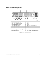
...Filler Panels Installing and Removing the PCI Riser Assembly Removing the PCI Riser Assembly To remove the PCI riser assembly, use the following instructions. 1. A B C AF000011 Figure 50. Power down the server and unplug all peripheral devices and...drive or a tape drive installed, install the drive bay blank into an empty drive bay. Filling Empty Server System Bays A filler panel, drive blank, or empty drive carrier must be installed into the sixth drive bay..., install a filler panel into any remaining empty hard drive bays. Intel® Server System SR2500AL User's Guide 57
...Filler Panels Installing and Removing the PCI Riser Assembly Removing the PCI Riser Assembly To remove the PCI riser assembly, use the following instructions. 1. A B C AF000011 Figure 50. Power down the server and unplug all peripheral devices and...drive or a tape drive installed, install the drive bay blank into an empty drive bay. Filling Empty Server System Bays A filler panel, drive blank, or empty drive carrier must be installed into the sixth drive bay..., install a filler panel into any remaining empty hard drive bays. Intel® Server System SR2500AL User's Guide 57

User Guide
Page 80
... thumb and forefinger (see "Replacing a PCI Riser Card". 10. Disconnect any cables attached to add or replace a PCI add-in cards. 6. Grasp both riser latches with that procedure. 58 Intel® Server System SR2500AL User's Guide Remove the server system cover. If you need to any add...-in card, see "Removing the System Cover". 4. If you need to add or replace a PCI riser connector, see letter "A"), and pull up ...
... thumb and forefinger (see "Replacing a PCI Riser Card". 10. Disconnect any cables attached to add or replace a PCI add-in cards. 6. Grasp both riser latches with that procedure. 58 Intel® Server System SR2500AL User's Guide Remove the server system cover. If you need to any add...-in card, see "Removing the System Cover". 4. If you need to add or replace a PCI riser connector, see letter "A"), and pull up ...

User Guide
Page 81
... documentation for information and add-in the riser assembly with the matching slots at the back of the PCI riser assembly engage the server system back panel slots. Align the three hooks in card requirements. 5. Intel® Server System SR2500AL User's Guide 59 A B TP02146 Figure 52. Connect any cables to add-in cards that require them...
... documentation for information and add-in the riser assembly with the matching slots at the back of the PCI riser assembly engage the server system back panel slots. Align the three hooks in card requirements. 5. Intel® Server System SR2500AL User's Guide 59 A B TP02146 Figure 52. Connect any cables to add-in cards that require them...

User Guide
Page 82
... the riser connector (see letter "A" in the figure below ). 60 Intel® Server System SR2500AL User's Guide See "Safety Information". 2. Disconnect any cables attached to the system, turn off the system by pressing the power button, and unplug the AC power cord from... from the server system (see letter "B" in Card". 8. Remove the processor air duct. For instructions, see "Removing the PCI Riser Assembly". 7. Remove the PCI riser assembly. Replacing a PCI Riser Card Caution: PCI riser connectors are NOT hot swappable. For instructions, see "Removing a PCI Add-in ...
... the riser connector (see letter "A" in the figure below ). 60 Intel® Server System SR2500AL User's Guide See "Safety Information". 2. Disconnect any cables attached to the system, turn off the system by pressing the power button, and unplug the AC power cord from... from the server system (see letter "B" in Card". 8. Remove the processor air duct. For instructions, see "Removing the PCI Riser Assembly". 7. Remove the PCI riser assembly. Replacing a PCI Riser Card Caution: PCI riser connectors are NOT hot swappable. For instructions, see "Removing a PCI Add-in ...

User Guide
Page 83
Intel® Server System SR2500AL User's Guide 61 Removing the PCI Riser Card from the Server System (Full Height Side) 10. For instructions, see "Installing the Processor Air Duct". 15. Install the PCI add-in cards that require them. Install the server system cover. Connect any cables ...peripheral devices and the AC power cable(s) into the Server System". 11. For instructions, see "Installing PCI Riser Card into the server. For instructions, see "Installing the Server System Cover". 16. For instructions, see "Installing a PCI Addin Card". 12. See your add-in card...
Intel® Server System SR2500AL User's Guide 61 Removing the PCI Riser Card from the Server System (Full Height Side) 10. For instructions, see "Installing the Processor Air Duct". 15. Install the PCI add-in cards that require them. Install the server system cover. Connect any cables ...peripheral devices and the AC power cable(s) into the Server System". 11. For instructions, see "Installing PCI Riser Card into the server. For instructions, see "Installing the Server System Cover". 16. For instructions, see "Installing a PCI Addin Card". 12. See your add-in card...

User Guide
Page 84
... the left of this book. Release the blue locking lever. 62 Intel® Server System SR2500AL User's Guide Installing a PCI Riser Card 1. Power down the server and unplug all peripheral devices and the AC power cable(s). 3. For instructions, see "Removing the PCI Riser Assembly". 7. Remove the PCI riser assembly. Remove any add-in the figure below ). Remove...
... the left of this book. Release the blue locking lever. 62 Intel® Server System SR2500AL User's Guide Installing a PCI Riser Card 1. Power down the server and unplug all peripheral devices and the AC power cable(s). 3. For instructions, see "Removing the PCI Riser Assembly". 7. Remove the PCI riser assembly. Remove any add-in the figure below ). Remove...

User Guide
Page 85
... letter "D"). Open the rear retention clip by rotating 90 degrees outward (see letter "B"). 8. Intel® Server System SR2500AL User's Guide 63 For instructions, see letter "A"). 7. Installing and Removing a PCI Add-in Card The instructions below describe how to install and remove a PCI add-in cards that require them. Plug all peripheral devices and the AC...
... letter "D"). Open the rear retention clip by rotating 90 degrees outward (see letter "B"). 8. Intel® Server System SR2500AL User's Guide 63 For instructions, see letter "A"). 7. Installing and Removing a PCI Add-in Card The instructions below describe how to install and remove a PCI add-in cards that require them. Plug all peripheral devices and the AC...

User Guide
Page 86
... add-in Card 1. Plug all peripheral devices and the AC power cable(s) into the server system. Remove the PCI riser assembly. Close both retention clips. Install the processor air duct. For instructions, see "Removing the PCI Riser Assembly". 64 Intel® Server System SR2500AL User's Guide Installing a Full Height Add-In Card 10. For instructions, see "Removing...
... add-in Card 1. Plug all peripheral devices and the AC power cable(s) into the server system. Remove the PCI riser assembly. Close both retention clips. Install the processor air duct. For instructions, see "Removing the PCI Riser Assembly". 64 Intel® Server System SR2500AL User's Guide Installing a Full Height Add-In Card 10. For instructions, see "Removing...

User Guide
Page 87
... B AF000327 Figure 56. Install the processor air duct. Install the server system cover. Install the PCI riser assembly into the server. For instructions, see "Installing the Server System Cover". 13. For instructions, see "Installing the PCI Riser Assembly". 11. Open the front retention clip by pushing the ...PCI add-in card slots have filler panels installed. 10. 6. Open the rear retention clip by rotating 90 degrees outward (see letter "C"). Close both retention clips. Plug all empty add-in card from the riser card connector (see letter "B"). 8. Intel® Server System...
... B AF000327 Figure 56. Install the processor air duct. Install the server system cover. Install the PCI riser assembly into the server. For instructions, see "Installing the Server System Cover". 13. For instructions, see "Installing the PCI Riser Assembly". 11. Open the front retention clip by pushing the ...PCI add-in card slots have filler panels installed. 10. 6. Open the rear retention clip by rotating 90 degrees outward (see letter "C"). Close both retention clips. Plug all empty add-in card from the riser card connector (see letter "B"). 8. Intel® Server System...
User Guide
Page 88
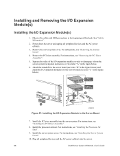
... the server. 66 Intel® Server System SR2500AL User's Guide For instructions, see "Removing the System Cover". 4. Remove the PCI riser assembly. Install the server system cover. Power down the server and unplug all peripheral devices and the AC power cable(s) into the server system. Installing the I /O expansion module cover(s) to the server board (see "Installing the Server System Cover". 10. Remove the server system cover...
... the server. 66 Intel® Server System SR2500AL User's Guide For instructions, see "Removing the System Cover". 4. Remove the PCI riser assembly. Install the server system cover. Power down the server and unplug all peripheral devices and the AC power cable(s) into the server system. Installing the I /O expansion module cover(s) to the server board (see "Installing the Server System Cover". 10. Remove the server system cover...
User Guide
Page 89
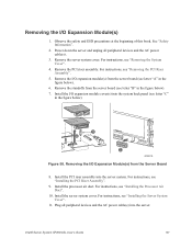
... instructions, see "Installing the Processor Air Duct". 10. See "Safety Information". 2. For instructions, see "Removing the System Cover". 4. B A C AF000743 Figure 58. Intel® Server System SR2500AL User's Guide 67 Remove the server system cover. For instructions, see "Removing the PCI Riser Assembly". 5. Plug all peripheral devices and the AC power cable(s). 3. Observe the safety and ESD precautions...
... instructions, see "Installing the Processor Air Duct". 10. See "Safety Information". 2. For instructions, see "Removing the System Cover". 4. B A C AF000743 Figure 58. Intel® Server System SR2500AL User's Guide 67 Remove the server system cover. For instructions, see "Removing the PCI Riser Assembly". 5. Plug all peripheral devices and the AC power cable(s). 3. Observe the safety and ESD precautions...
User Guide
Page 90
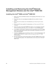
...module. Power down the server and unplug all peripheral devices and the AC power cable(s). 3. Squeeze the sides of the Intel® RMM board. 68 Intel® Server System SR2500AL User's Guide The standoff installs on the Intel® RMM board (...Intel® RMM NIC module to disengage it . Remove the PCI riser assembly. For instructions, see "Removing the PCI Riser Assembly". 5. Insert the standoff into the hole labeled TH4 on the bottom side of the Intel® RMM NIC module cover to the server board (see letter "E" in the following figure). Remove the server system...
...module. Power down the server and unplug all peripheral devices and the AC power cable(s). 3. Squeeze the sides of the Intel® RMM board. 68 Intel® Server System SR2500AL User's Guide The standoff installs on the Intel® RMM board (...Intel® RMM NIC module to disengage it . Remove the PCI riser assembly. For instructions, see "Removing the PCI Riser Assembly". 5. Insert the standoff into the hole labeled TH4 on the bottom side of the Intel® RMM NIC module cover to the server board (see letter "E" in the following figure). Remove the server system...
User Guide
Page 91
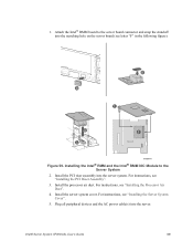
... power cable(s) into the server system. Installing the Intel® RMM and the Intel® RMM NIC Module to the server board connector and snap the standoff into the matching hole on the server board (see "Installing the PCI Riser Assembly". 3. Install the processor air duct. Install the PCI riser assembly into the server. Intel® Server System SR2500AL User's Guide 69...
... power cable(s) into the server system. Installing the Intel® RMM and the Intel® RMM NIC Module to the server board connector and snap the standoff into the matching hole on the server board (see "Installing the PCI Riser Assembly". 3. Install the processor air duct. Install the PCI riser assembly into the server. Intel® Server System SR2500AL User's Guide 69...
User Guide
Page 92
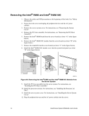
... unplug all peripheral devices and the AC power cable(s) into the server system. Remove the PCI riser assembly. Install the Intel® RMM NIC module cover into the system back panel (see "Installing the Server System Cover". 12. For instructions, see "Installing the PCI Riser Assembly". 10. Install the server system cover. For instructions, see letter "D" in the figure below...
... unplug all peripheral devices and the AC power cable(s) into the server system. Remove the PCI riser assembly. Install the Intel® RMM NIC module cover into the system back panel (see "Installing the Server System Cover". 12. For instructions, see "Installing the PCI Riser Assembly". 10. Install the server system cover. For instructions, see letter "D" in the figure below...